Page 134 of 524
Features of your vehicle
64
4
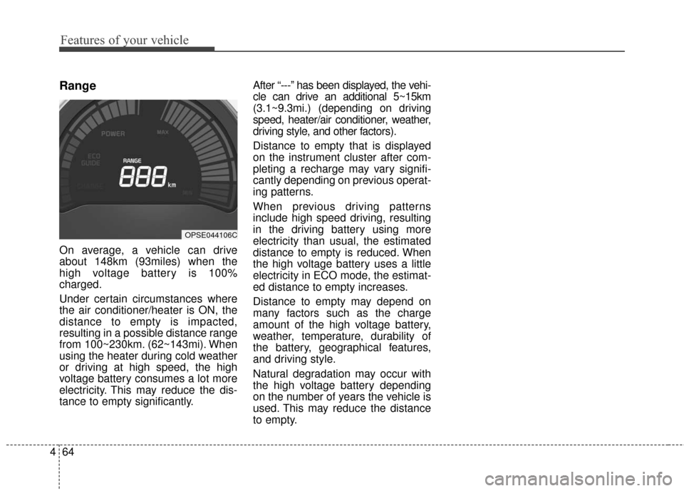
Range
On average, a vehicle can drive
about 148km (93miles) when the
high voltage battery is 100%
charged.
Under certain circumstances where
the air conditioner/heater is ON, the
distance to empty is impacted,
resulting in a possible distance range
from 100~230km. (62~143mi). When
using the heater during cold weather
or driving at high speed, the high
voltage battery consumes a lot more
electricity. This may reduce the dis-
tance to empty significantly. After “---” has been displayed, the vehi-
cle can drive an additional 5~15km
(3.1~9.3mi.) (depending on driving
speed, heater/air conditioner, weather,
driving style, and other factors).
Distance to empty that is displayed
on the instrument cluster after com-
pleting a recharge may vary signifi-
cantly depending on previous operat-
ing patterns.
When previous driving patterns
include high speed driving, resulting
in the driving battery using more
electricity than usual, the estimated
distance to empty is reduced. When
the high voltage battery uses a little
electricity in ECO mode, the estimat-
ed distance to empty increases.
Distance to empty may depend on
many factors such as the charge
amount of the high voltage battery,
weather, temperature, durability of
the battery, geographical features,
and driving style.
Natural degradation may occur with
the high voltage battery depending
on the number of years the vehicle is
used. This may reduce the distance
to empty.
OPSE044106C
Page 309 of 524
59
Driving your vehicle
Turing off the Vehicle
1. Depress the brake pedal fully.
2. Place the shift lever in the P(Park).
3. Apply the parking brake firmly.
4. Press the POWER button to turn the vehicle off.
5. Make sure the " (ready)" indi- cator lights on the instrument clus-
ter are turned off.
✽ ✽
NOTICE
If the " (ready)" indicator light
on the instrument cluster is still on,
be careful that the vehicle is not
turned off and can move when you
place the shift lever in any position
except P (Park).
OPSE054006
Page 328 of 524
Driving your vehicle
28
5
✽ ✽
NOTICE
• When operating the vehicle on a
dynamometer, ensure that the
ESC is turned off (ESC OFF light
illuminated). If the ESC is left on,
it may prevent the vehicle speed
from increasing, and result in false
diagnosis.
• Turning the ESC off does not affect ABS or brake system opera-
tion.
Vehicle stability management
(VSM)
This system provides further
enhancements to vehicle stability
and steering responses when a vehi-
cle is driving on a slippery road or a
vehicle detects changes in coeffi-
cient of friction between right wheels
and left wheels when braking.
VSM operation
When the VSM is in operation, ESC
indicator light ( ) blinks.
When the vehicle stability manage-
ment is operating properly, you can
feel a slight pulsation in the vehicle
and/or abnormal steering responses
(EPS). This is only the effect of brake
and EPS control and indicates noth-
ing unusual. The VSM does not operate when:
Driving on bank road such as gra-
dient or incline
Driving in reverse
ESC OFF indicator light ( ) remains on the instrument cluster
EPS indicator light remains on the instrument cluster
VSM operation off
If you press the ESC OFF button to
turn off the ESC, the VSM will also
cancel and the ESC OFF indicator
light ( ) illuminates.
To turn on the VSM, press the button
again. The ESC OFF indicator light
goes out.
Page 332 of 524
Driving your vehicle
32
5
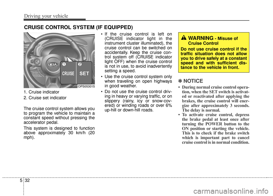
1. Cruise indicator
2. Cruise set indicator
The cruise control system allows you
to program the vehicle to maintain a
constant speed without pressing the
accelerator pedal.
This system is designed to function
above approximately 30 km/h (20
mph). If the cruise control is left on
(CRUISE indicator light in the
instrument cluster illuminated), the
cruise control can be switched on
accidentally. Keep the cruise con-
trol system off (CRUISE indicator
light OFF) when the cruise control
is not in use, to avoid inadvertently
setting a speed.
Use the cruise control system only when traveling on open highways
in good weather.
Do not use the cruise control driv- ing in heavy or varying traffic, or on
slippery (rainy, icy or snow-cov-
ered) or winding roads or over 6%
up-hill or down-hill roads.
✽ ✽ NOTICE
• During normal cruise control opera-
tion, when the SET switch is activat-
ed or reactivated after applying the
brakes, the cruise control will ener-
gize after approximately 3 seconds.
The delay is normal.
• To activate cruise control, depress the brake pedal at least once after
turning the POWER button to the
ON position or starting the vehicle.
This is to check if the brake switch
which is important part to cancel
cruise control is in normal condition.
CRUISE CONTROL SYSTEM (IF EQUIPPED)
OPS053015
WARNING- Misuse of
Cruise Control
Do not use cruise control if the
traffic situation does not allow
you to drive safely at a constant
speed and with sufficient dis-
tance to the vehicle in front.
Page 333 of 524
533
Driving your vehicle
Cruise control switch
CRUISE : Turns cruise control sys-tem on or off.
CANCEL: Cancels cruise control
operation.
RES+: Resumes or increases cruise control speed.
SET-: Sets or decreases cruise con- trol speed.
To set cruise control speed:
1. Press the CRUISE button on thesteering wheel to turn the system
on. The CRUISE indicator light in
the instrument cluster will illumi-
nate.
2. Accelerate to the desired speed, which must be more than 30 km/h
(20 mph). 3. Push the SET - switch, and
release it at the desired speed.
The SET indicator light in the
instrument cluster will illuminate.
Release the accelerator pedal at
the same time. The desired speed
will automatically be maintained.
On a steep grade, the vehicle mayslow down or speed up slightly whilegoing uphill or downhill.
OPS053016OPS053017
OPS053018
Page 336 of 524
Driving your vehicle
36
5
To turn cruise control off, do
one of the following:
Press the CRUISE button (the
CRUISE indicator light in the
instrument cluster will go off).
Turn the vehicle off.
Both of these actions cancel cruise control operation. If you want toresume cruise control operation,repeat the steps provided in “To setcruise control speed” on the previouspage.
OPS053017
Page 427 of 524
753
Maintenance
Instrument panel (Driver’s side fuse panel)
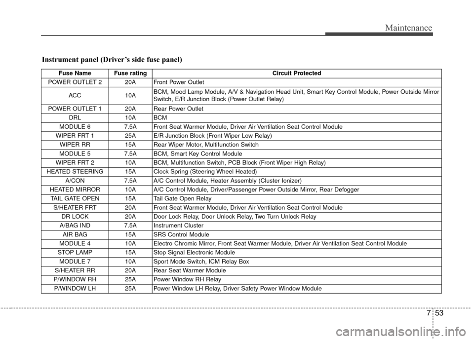
Fuse Name Fuse ratingCircuit Protected
POWER OUTLET 2 20A Front Power Outlet
ACC 10A BCM, Mood Lamp Module, A/V & Navigation Head Unit, Smart Key Control Module, Power Outside Mirror
Switch, E/R Junction Block (Power Outlet Relay)
POWER OUTLET 1 20A Rear Power Outlet DRL 10A BCM
MODULE 6 7.5A Front Seat Warmer Module, Driver Air Ventilation Seat Control Module
WIPER FRT 1 25A E/R Junction Block (Front Wiper Low Relay) WIPER RR 15A Rear Wiper Motor, Multifunction Switch
MODULE 5 7.5A BCM, Smart Key Control Module
WIPER FRT 2 10A BCM, Multifunction Switch, PCB Block (Front Wiper High Relay)
HEATED STEERING 15A Clock Spring (Steering Wheel Heated) A/CON 7.5A A/C Control Module, Heater Assembly (Cluster Ionizer)
HEATED MIRROR 10A A/C Control Module, Driver/Passenger Power Outside Mirror, Rear Defogger TAIL GATE OPEN 15A Tail Gate Open Relay S/HEATER FRT 20A Front Seat Warmer Module, Driver Air Ventilation Seat Control Module DR LOCK 20A Door Lock Relay, Door Unlock Relay, Two Turn Unlock Relay
A/BAG IND 7.5A Instrument Cluster
AIR BAG 15A SRS Control Module
MODULE 4 10A Electro Chromic Mirror, Front Seat Warmer Module, Driver Air Ventilation Seat Control Module
STOP LAMP 15A Stop Signal Electronic Module
MODULE 7 10A Sport Mode Switch, ICM Relay Box
S/HEATER RR 20A Rear Seat Warmer Module
P/WINDOW RH 25A Power Window RH Relay P/WINDOW LH 25A Power Window LH Relay, Driver Safety Power Window Module
Page 428 of 524
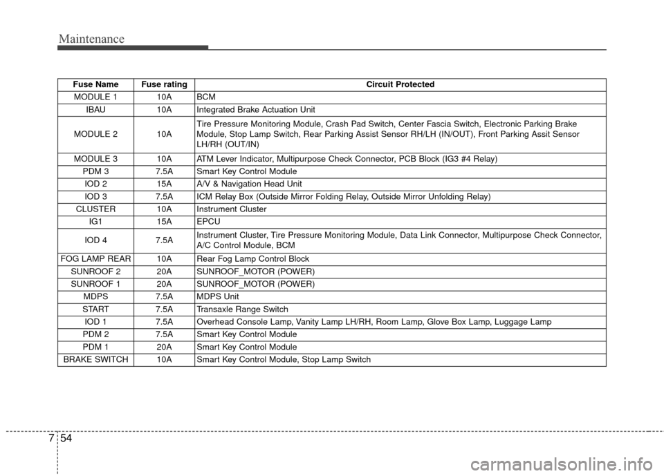
Maintenance
54
7
Fuse Name Fuse rating Circuit Protected
MODULE 1 10A BCM IBAU 10A Integrated Brake Actuation Unit
MODULE 2 10A Tire Pressure Monitoring Module, Crash Pad Switch, Center Fascia Switch, Electronic Parking Brake
Module, Stop Lamp Switch, Rear Parking Assist Sensor RH/LH (IN/OUT), Front Parking Assit Sensor
LH/RH (OUT/IN)
MODULE 3 10A ATM Lever Indicator, Multipurpose Check Connector, PCB Block (IG3 #4 Relay) PDM 3 7.5A Smart Key Control Module
IOD 2 15A A/V & Navigation Head Unit
IOD 3 7.5A ICM Relay Box (Outside Mirror Folding Relay, Outside Mirror Unfolding Relay)
CLUSTER 10A Instrument Cluster IG1 15A EPCU
IOD 4 7.5A Instrument Cluster, Tire Pressure Monitoring Module, Data Link Connector, Multipurpose Check Connector,
A/C Control Module, BCM
FOG LAMP REAR 10A Rear Fog Lamp Control Block SUNROOF 2 20A SUNROOF_MOTOR (POWER)
SUNROOF 1 20A SUNROOF_MOTOR (POWER) MDPS 7.5A MDPS Unit
START 7.5A Transaxle Range Switch
IOD 1 7.5A Overhead Console Lamp, Vanity Lamp LH/RH, Room Lamp, Glove Box Lamp, Luggage Lamp
PDM 2 7.5A Smart Key Control Module
PDM 1 20A Smart Key Control Module
BRAKE SWITCH 10A Smart Key Control Module, Stop Lamp Switch