2016 KIA Soul EV key
[x] Cancel search: keyPage 345 of 524
545
Driving your vehicle
Use high quality ethylene gly-
col coolant
Your vehicle is delivered with high qual-
ity ethylene glycol coolant in the cool-
ing system. It is the only type of coolant
that should be used because it helps
prevent corrosion in the cooling sys-
tem, lubricates the water pump and
prevents freezing. Be sure to replace
or replenish your coolant in accor-
dance with the maintenance schedule
in section 7. Before winter, have your
coolant tested to assure that its freez-
ing point is sufficient for the tempera-
tures anticipated during the winter.
Check battery and cables
Winter puts additional burdens on the
battery system. Visually inspect the
battery and cables as described in
section 7. The level of charge in your
battery can be checked by an author-
ized Kia dealer or a service station.
To keep locks from freezing
To keep the locks from freezing,
squirt an approved de-icer fluid or
glycerine into the key opening. If a
lock is covered with ice, squirt it with
an approved de-icing fluid to remove
the ice. If the lock is frozen internally,
you may be able to thaw it out by
using a heated key. Handle the heat-
ed key with care to avoid injury.
Use approved window washer
anti-freeze in system
To keep the water in the window
washer system from freezing, add an
approved window washer anti-freeze
solution in accordance with instruc-
tions on the container. Window wash-
er anti-freeze is available from an
authorized Kia dealer and most auto
parts outlets. Do not use coolant or
other types of anti-freeze as these
may damage the paint finish.
Page 424 of 524
Maintenance
50
7
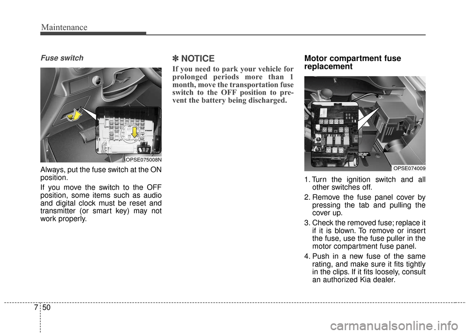
Fuse switch
Always, put the fuse switch at the ON
position.
If you move the switch to the OFF
position, some items such as audio
and digital clock must be reset and
transmitter (or smart key) may not
work properly.
✽ ✽
NOTICE
If you need to park your vehicle for
prolonged periods more than 1
month, move the transportation fuse
switch to the OFF position to pre-
vent the battery being discharged.
Motor compartment fuse
replacement
1. Turn the ignition switch and all
other switches off.
2. Remove the fuse panel cover by pressing the tab and pulling the
cover up.
3. Check the removed fuse; replace it if it is blown. To remove or insert
the fuse, use the fuse puller in the
motor compartment fuse panel.
4. Push in a new fuse of the same rating, and make sure it fits tightly
in the clips. If it fits loosely, consult
an authorized Kia dealer.
OPSE074009
OPSE075008N
Page 427 of 524
753
Maintenance
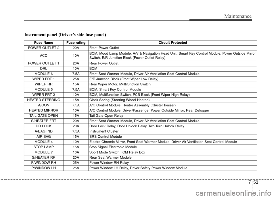
Instrument panel (Driver’s side fuse panel)
Fuse Name Fuse ratingCircuit Protected
POWER OUTLET 2 20A Front Power Outlet
ACC 10A BCM, Mood Lamp Module, A/V & Navigation Head Unit, Smart Key Control Module, Power Outside Mirror
Switch, E/R Junction Block (Power Outlet Relay)
POWER OUTLET 1 20A Rear Power Outlet DRL 10A BCM
MODULE 6 7.5A Front Seat Warmer Module, Driver Air Ventilation Seat Control Module
WIPER FRT 1 25A E/R Junction Block (Front Wiper Low Relay) WIPER RR 15A Rear Wiper Motor, Multifunction Switch
MODULE 5 7.5A BCM, Smart Key Control Module
WIPER FRT 2 10A BCM, Multifunction Switch, PCB Block (Front Wiper High Relay)
HEATED STEERING 15A Clock Spring (Steering Wheel Heated) A/CON 7.5A A/C Control Module, Heater Assembly (Cluster Ionizer)
HEATED MIRROR 10A A/C Control Module, Driver/Passenger Power Outside Mirror, Rear Defogger TAIL GATE OPEN 15A Tail Gate Open Relay S/HEATER FRT 20A Front Seat Warmer Module, Driver Air Ventilation Seat Control Module DR LOCK 20A Door Lock Relay, Door Unlock Relay, Two Turn Unlock Relay
A/BAG IND 7.5A Instrument Cluster
AIR BAG 15A SRS Control Module
MODULE 4 10A Electro Chromic Mirror, Front Seat Warmer Module, Driver Air Ventilation Seat Control Module
STOP LAMP 15A Stop Signal Electronic Module
MODULE 7 10A Sport Mode Switch, ICM Relay Box
S/HEATER RR 20A Rear Seat Warmer Module
P/WINDOW RH 25A Power Window RH Relay P/WINDOW LH 25A Power Window LH Relay, Driver Safety Power Window Module
Page 428 of 524
Maintenance
54
7
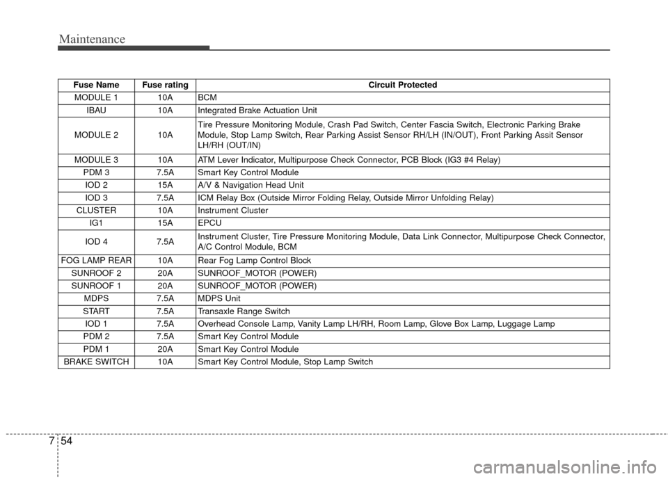
Fuse Name Fuse rating Circuit Protected
MODULE 1 10A BCM IBAU 10A Integrated Brake Actuation Unit
MODULE 2 10A Tire Pressure Monitoring Module, Crash Pad Switch, Center Fascia Switch, Electronic Parking Brake
Module, Stop Lamp Switch, Rear Parking Assist Sensor RH/LH (IN/OUT), Front Parking Assit Sensor
LH/RH (OUT/IN)
MODULE 3 10A ATM Lever Indicator, Multipurpose Check Connector, PCB Block (IG3 #4 Relay) PDM 3 7.5A Smart Key Control Module
IOD 2 15A A/V & Navigation Head Unit
IOD 3 7.5A ICM Relay Box (Outside Mirror Folding Relay, Outside Mirror Unfolding Relay)
CLUSTER 10A Instrument Cluster IG1 15A EPCU
IOD 4 7.5A Instrument Cluster, Tire Pressure Monitoring Module, Data Link Connector, Multipurpose Check Connector,
A/C Control Module, BCM
FOG LAMP REAR 10A Rear Fog Lamp Control Block SUNROOF 2 20A SUNROOF_MOTOR (POWER)
SUNROOF 1 20A SUNROOF_MOTOR (POWER) MDPS 7.5A MDPS Unit
START 7.5A Transaxle Range Switch
IOD 1 7.5A Overhead Console Lamp, Vanity Lamp LH/RH, Room Lamp, Glove Box Lamp, Luggage Lamp
PDM 2 7.5A Smart Key Control Module
PDM 1 20A Smart Key Control Module
BRAKE SWITCH 10A Smart Key Control Module, Stop Lamp Switch
Page 463 of 524
Index
6I
POWER button . . . . . . . . . . . . . . . . . . . . . . . . . . . . . . . . 5-5Illuminated POWER button . . . . . . . . . . . . . . . . . . . . 5-5
Pedestrian Warning System . . . . . . . . . . . . . . . . . . . . 5-8
POWER button position . . . . . . . . . . . . . . . . . . . . . . . 5-5
Starting the vehicle. . . . . . . . . . . . . . . . . . . . . . . . . . . 5-7
Turing off the Vehicle. . . . . . . . . . . . . . . . . . . . . . . . . 5-9
Power electric specifications . . . . . . . . . . . . . . . . . . . . . 8-2
Rear camera display . . . . . . . . . . . . . . . . . . . . . . . . . . . 4-80
Recommended lubricants and capacities . . . . . . . . . . . . 8-6
Reduction gear . . . . . . . . . . . . . . . . . . . . . . . . . . . . . . . 5-11 Good driving practices . . . . . . . . . . . . . . . . . . . . . . . 5-15
Reduction gear operation . . . . . . . . . . . . . . . . . . . . . 5-12
Road warning . . . . . . . . . . . . . . . . . . . . . . . . . . . . . . . . . 6-2 Hazard warning flasher . . . . . . . . . . . . . . . . . . . . . . . 6-2
Scheduled maintenance service . . . . . . . . . . . . . . . . . . . 7-7
Seat belts . . . . . . . . . . . . . . . . . . . . . . . . . . . . . . . . . . . . \
3-12 Care of seat belts . . . . . . . . . . . . . . . . . . . . . . . . . . . 3-25
Pre-tensioner seat belt . . . . . . . . . . . . . . . . . . . . . . . 3-20
Seat belt precautions . . . . . . . . . . . . . . . . . . . . . . . . 3-22
Seat belt restraint system . . . . . . . . . . . . . . . . . . . . . 3-12
Seats . . . . . . . . . . . . . . . . . . . . . . . . . . . . . . . . . . . . \
. . . . 3-2 Front seat adjustment . . . . . . . . . . . . . . . . . . . . . . . . 3-5 Rear seat adjustment . . . . . . . . . . . . . . . . . . . . . . . . . 3-9
Seatback pocket . . . . . . . . . . . . . . . . . . . . . . . . . . . . . 3-8
Smart key . . . . . . . . . . . . . . . . . . . . . . . . . . . . . . . . . . . . \
4-4 Battery replacement . . . . . . . . . . . . . . . . . . . . . . . . . 4-10
Loss of the smart key . . . . . . . . . . . . . . . . . . . . . . . . . 4-7
Record your key number . . . . . . . . . . . . . . . . . . . . . . 4-4
Smart key function . . . . . . . . . . . . . . . . . . . . . . . . . . . 4-4
Smart key immobilizer system. . . . . . . . . . . . . . . . . . 4-8
Smart key precautions . . . . . . . . . . . . . . . . . . . . . . . . 4-8
Special driving conditions . . . . . . . . . . . . . . . . . . . . . . 5-39 Driving at night . . . . . . . . . . . . . . . . . . . . . . . . . . . . 5-41
Driving in flooded areas. . . . . . . . . . . . . . . . . . . . . . 5-42
Driving in the rain . . . . . . . . . . . . . . . . . . . . . . . . . . 5-42
Driving off-road . . . . . . . . . . . . . . . . . . . . . . . . . . . . 5-43
Hazardous driving conditions . . . . . . . . . . . . . . . . . 5-39
Highway driving . . . . . . . . . . . . . . . . . . . . . . . . . . . . 5-43
Reducing the risk of a rollover. . . . . . . . . . . . . . . . . 5-39
Rocking the vehicle . . . . . . . . . . . . . . . . . . . . . . . . . 5-40
Smooth cornering . . . . . . . . . . . . . . . . . . . . . . . . . . . 5-41
Steering wheel . . . . . . . . . . . . . . . . . . . . . . . . . . . . . . . 4-30 Electric power steering (EPS) . . . . . . . . . . . . . . . . . 4-30
FLEX STEER. . . . . . . . . . . . . . . . . . . . . . . . . . . . . . 4-33
Heated steering wheel . . . . . . . . . . . . . . . . . . . . . . . 4-32
Horn . . . . . . . . . . . . . . . . . . . . . . . . . . . . . . . . . . . . \
. 4-32
Tilt and telescopic steering . . . . . . . . . . . . . . . . . . . 4-31
Storage compartment . . . . . . . . . . . . . . . . . . . . . . . . . 4-115 Center console storage . . . . . . . . . . . . . . . . . . . . . . 4-115
Glove box . . . . . . . . . . . . . . . . . . . . . . . . . . . . . . . . 4-115
R
S
Page 489 of 524
24
Depending on the condition and
durability of the high voltage battery,
charger specifications, and ambient
temperature, the time required for
charging the battery may vary.11.You may prevent possible charg-
ing cable theft by taking the fol-
lowing steps. Lock the door after
the charging cable is connected,
by pressing the lock button on the
smart key or on the central door
lock switch.
When the door is locked, the
charging connector will become
locked and this will prevent possi-
ble theft.
So, after charging is complete,
you must release the door lock in
order to disconnect the charging
connector.
■ ■Unlock Charging Door in
Emergency
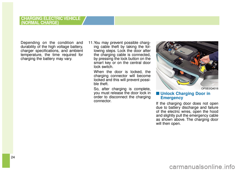
If the charging door does not open
due to battery discharge and failure
of the electric wires, open the hood
and slightly pull the emergency cable
as shown above. The charging door
will then open.
CHARGING ELECTRIC VEHICLE
(NORMAL CHARGE)
OPSE0Q4016
Page 502 of 524
37
Depending on the condition and
durability of the high voltage battery,
charger specifications, and ambient
temperature, the time required for
charging the battery may vary.14.You may prevent possible charg-
ing cable theft by taking the fol-
lowing steps. Lock the door after
the charging cable is connected,
by pressing the lock button on the
smart key or on the central door
lock switch.
When the door is locked, the
charging connector will become
locked and this will prevent possi-
ble theft.
So, after charging is complete,
you must release the door lock in
order to disconnect the charging
connector.
■ ■Unlock Charging Door in
Emergency
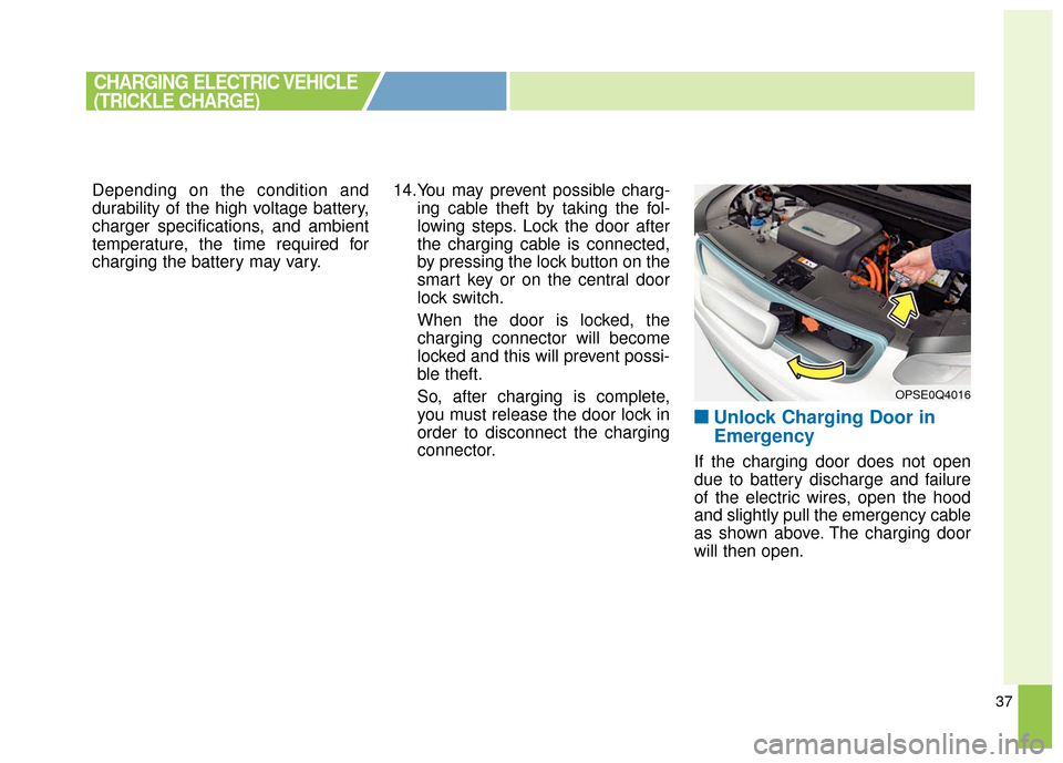
If the charging door does not open
due to battery discharge and failure
of the electric wires, open the hood
and slightly pull the emergency cable
as shown above. The charging door
will then open.
CHARGING ELECTRIC VEHICLE
(TRICKLE CHARGE)
OPSE0Q4016
Page 508 of 524
43
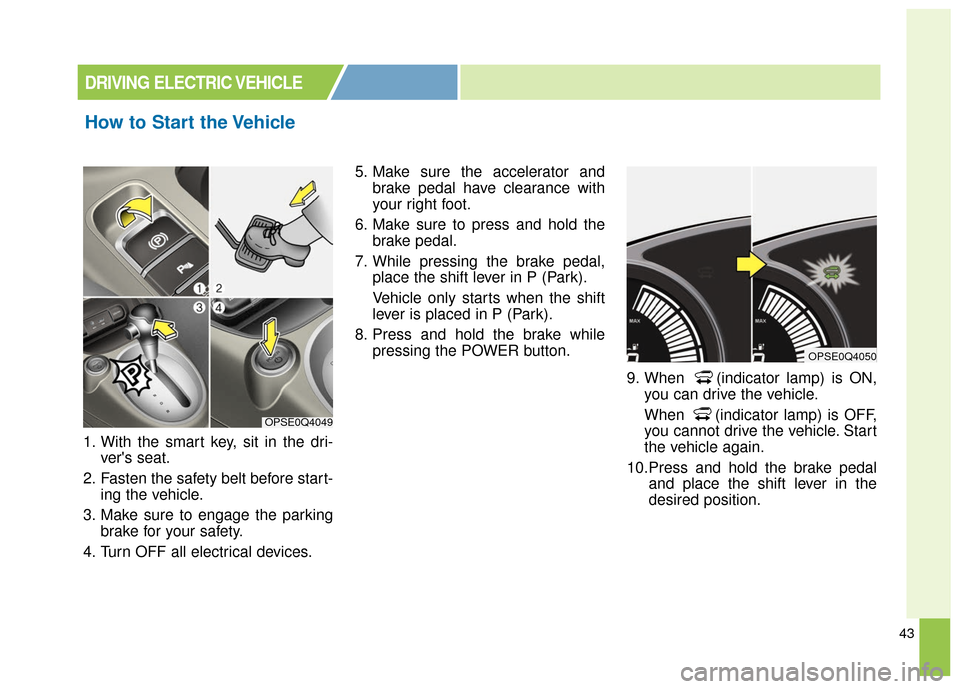
1. With the smart key, sit in the dri-ver's seat.
2. Fasten the safety belt before start- ing the vehicle.
3. Make sure to engage the parking brake for your safety.
4. Turn OFF all electrical devices. 5. Make sure the accelerator and
brake pedal have clearance with
your right foot.
6. Make sure to press and hold the brake pedal.
7. While pressing the brake pedal, place the shift lever in P (Park).
Vehicle only starts when the shift
lever is placed in P (Park).
8. Press and hold the brake while pressing the POWER button.
9. When (indicator lamp) is ON,you can drive the vehicle.
When (indicator lamp) is OFF,
you cannot drive the vehicle. Start
the vehicle again.
10.Press and hold the brake pedal and place the shift lever in the
desired position.
How to Start the Vehicle
DRIVING ELECTRIC VEHICLE
OPSE0Q4049
OPSE0Q4050