Page 519 of 565
775
Maintenance
DescriptionFuse ratingProtected component
MULTIFUSE
MDPS 1100AMDPS Unit (Rack Type)
MDPS 280AMDPS Unit (Column Type)
COOLING FAN 180ACooling Fan 1 Relay
B+160AIGPM (Fuse - S/HEATER (RR), P/SEAT (DRV), P/SEAT (PASS), P/WINDOW (LH))
B+260AIGPM (Fuse - S/HEATER (FRT), P/WINDOW (RH), FULE LID, AMP 1, AMP 2)
B+360AIGPM (IPS 1, Fuse - MODULE 7, Leak Current Autocut Device Fuse - MULTIMEDIA, MEMORY 2,
MEMORY 1), INTERIOR LAMP
B+550AIGPM (IPS 0/IPS 2/IPS 3/IPS 4/IPS 5/IPS 6/IPS 7/IPS 8, Fuse - S/ROOF 1)
FUSE
B+440AIGPM (Fuse - DOOR LOCK, SMART KEY 1, SMART KEY 2, BRAKE SWITCH, A/CON (RR),
S/ROOF 2)
ABS 220AESC Module
ABS 140AESC Module, Multipurpose Check Connector
INVERTER30AAC Inverter Module
POWER TAIL GATE 30APower Tail Gate Module
TRAILER30ATrailer Power Outlet
BLOWER40ABlower Relay
UM CAN (ENG) 7.qxp 12/1/2014 1:19 PM Page 75
Page 522 of 565
Maintenance
78
7
DescriptionFuse ratingProtected component
POWER
OUTLET 3 20ARear Power Outlet
SENSOR 1 20A[G4KJ/G4KH] Ignition Coil #1/#2/#3/#4 [G6DF] Ignition Coil #1/#2/#3/#4/#\
5/#6, Condecser #1/#2
SENSOR 3 10A[G4KJ/G4KH] Fuel Pump Relay [G6DF] Fuel Pump Relay, PCM
POWER
OUTLET 4 20ALuggage Power Outlet
REAR
HEATED 40ARear Defogger Relay
SENSOR 2 10A
[G4KJ/G4KH] E/R Junction Block (Cooling Fan 1 Relay), Oil Control Valve (Exhaust), Purge Control Solenoid Valve, Canister Close Valve, Variable Intake Solenoid Valve, RCV Control Solenoid Valve (G4KH)
[G6DH] E/R Junction Block (Cooling Fan 1 Relay), Variable Intake Solenoid Valve #1/#2, Purge Control Solenoid Valve, Oil Control Valve #1/#2/#3/#4 (Intake/Exhaust), PCM, Canister close valve
FUEL PUMP 20AFuel Pump Relay
HORN 15AHorn Relay
B/ALARMHORN 10ABurglar Alarm Horn Relay
UM CAN (ENG) 7.qxp 12/1/2014 1:19 PM Page 78
Page 524 of 565

Maintenance
80
7
LIGHT BULBS
Please prepare lamps with appropri-
ate standards in case of emergen-
cies. (Refer to chapter 8 for further
information)
When changing lamps and sorts,
first turn off the engine at a safe
place, firmly apply the side brake and
take out the battery’s negative (-) ter-
minal.Use only the bulbs of the specified
wattage.✽ ✽ NOTICE
• If the light bulb or lamp connector
is removed from an operating
lamp activated by electricity, the
fuse box’s electronic device may
scan it as a malfunction.
Therefore, a lamp malfunction
history may be recorded in
Diagnostic Trouble Code (DTC) in
the fuse box.
• It is normal for an operating lamp may blink temporarily. Since this
occurrence is due stabilization
function of the vehicle’s electronic
control device, if the lamp lights
up normally after temporary
blinking, there is no problem in
the vehicle.
However, if the lamp continues to
blink several times or turn off
completely, there may be an error
in the vehicle’s electronic control
device. So please have the vehicle
checked by an authorized Kia
dealer immediately.
WARNING - Working on
the lights
Prior to working on the light,
firmly apply the parking brake,
ensure that the ignition switch
is turned to the LOCK position
and turn off the lights to avoid
sudden movement of the vehi-
cle and burning your fingers or
receiving an electric shock.
CAUTION -Light replace-
ment
Be sure to replace the burned-
out bulb with one of the samewattage rating. Otherwise, itmay cause damage to the fuseor electric wiring system.
CAUTION -Headlamp
Lens
To prevent damage, do no cleanheadlamp lens with chemicalsolvents or strong detergents.
UM CAN (ENG) 7.qxp 12/1/2014 1:19 PM Page 80
Page 527 of 565

783
Maintenance
Headlamp (bulb type) -high/low
1. Open the hood.
2. Remove the headlamp assemblyfrom the body of the vehicle
3. Remove the headlamp bulb cover by turning it counterclockwise.
4. Remove the socket from the assembly by turning the socket
counterclockwise until the tabs on
the socket align with the slots on
the assembly.
5. Remove the bulb by pulling it out.
6. Inset a new bulb into the socket. 7. Install the socket in the assembly
by aligning the tabs on the socket
with the slots in the assembly.
Push the socket into the assembly
and turn the socket clockwise.
8. Install the headlamp bulb cover by turning it clockwise.
Turn signal lamp
Follow the steps 1 to 3 from the pre-
vious page.
4. Remove the socket from theassembly by turning the socket
counterclockwise until the tabs on
the socket align with the slots on
the assembly.
5. Remove the bulb from the socket by pressing it in and rotating it
counterclockwise until the tabs on
the bulb align with the slots in the
socket. Pull the bulb out of the
socket
OUM074108L
Turn signal
OUM074053L
High lamp Low lamp
UM CAN (ENG) 7.qxp 12/1/2014 1:19 PM Page 83
Page 528 of 565

Maintenance
84
7
6. Insert a new bulb by inserting it
into the socket and rotating it until
it locks into place.
7. Install the socket in the assembly by aligning the tabs on the socket
with the slots in the assembly.
Push the socket into the assembly
and turn the socket clockwise.
✽ ✽NOTICE
If bulb will not rotate inside socket,
remove bulb, rotate 180°, and try
again.
Front fog lamp bulbs
(if equipped)
1. Remove the front bumper under cover.
2. Reach your hand into the back of the front bumper.
3. Disconnect the power connector from the socket.
4. Remove the bulb-socket from the housing by turning the socket
counter clockwise until the tabs on
the socket align with the slots on
the housing. 5. Install the new bulb-socket into the
housing by aligning the tabs on
the socket with the slots in the
housing. Push the socket into the
housing and turn the socket clock-
wise.
6. Connect the power connector to the socket.
7. Reinstall the front bumper under cover.
✽ ✽NOTICE
Always have the headlamp aiming
adjusted after an accident or after
the headlamp assembly is reinstalled
at an authorized Kia dealer.OUMA074109
UM CAN (ENG) 7.qxp 12/1/2014 1:19 PM Page 84
Page 531 of 565

787
Maintenance
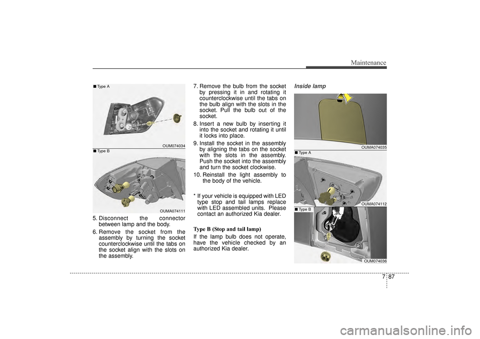
5. Disconnect the connectorbetween lamp and the body.
6. Remove the socket from the assembly by turning the socket
counterclockwise until the tabs on
the socket align with the slots on
the assembly. 7. Remove the bulb from the socket
by pressing it in and rotating it
counterclockwise until the tabs on
the bulb align with the slots in the
socket. Pull the bulb out of the
socket.
8. Insert a new bulb by inserting it into the socket and rotating it until
it locks into place.
9. Install the socket in the assembly by aligning the tabs on the socket
with the slots in the assembly.
Push the socket into the assembly
and turn the socket clockwise.
10. Reinstall the light assembly to the body of the vehicle.
* If your vehicle is equipped with LED type stop and tail lamps replace
with LED assembled units. Please
contact an authorized Kia dealer.
Type B (Stop and tail lamp)
If the lamp bulb does not operate,
have the vehicle checked by an
authorized Kia dealer.
Inside lamp
OUMA074035
OUMA074112
OUM074036
■ Type A
■Type B
OUM074034
OUMA074111
■
Type A
■ Type B
UM CAN (ENG) 7.qxp 12/1/2014 1:20 PM Page 87
Page 532 of 565

Maintenance
88
7
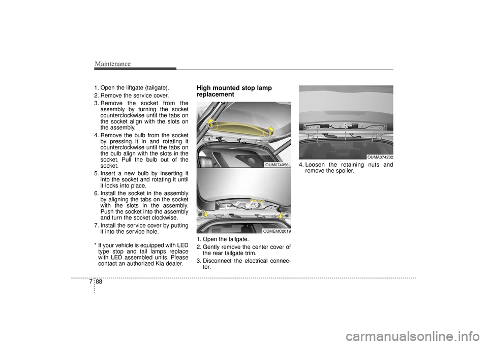
1. Open the liftgate (tailgate).
2. Remove the service cover.
3. Remove the socket from the
assembly by turning the socket
counterclockwise until the tabs on
the socket align with the slots on
the assembly.
4. Remove the bulb from the socket by pressing it in and rotating it
counterclockwise until the tabs on
the bulb align with the slots in the
socket. Pull the bulb out of the
socket.
5. Insert a new bulb by inserting it into the socket and rotating it until
it locks into place.
6. Install the socket in the assembly by aligning the tabs on the socket
with the slots in the assembly.
Push the socket into the assembly
and turn the socket clockwise.
7. Install the service cover by putting it into the service hole.
* If your vehicle is equipped with LED type stop and tail lamps replace
with LED assembled units. Please
contact an authorized Kia dealer.High mounted stop lamp
replacement
1. Open the tailgate.
2. Gently remove the center cover of the rear tailgate trim.
3. Disconnect the electrical connec- tor. 4. Loosen the retaining nuts and
remove the spoiler.
OUM074056L
ODMEMC2019
OUMA074232
UM CAN (ENG) 7.qxp 12/1/2014 1:20 PM Page 88
Page 555 of 565
10
8
Specifications & Consumer information
The tires supplied on your new vehi-
cle are chosen to provide the best
performance for normal driving.
The tire label located on the driver's
side center pillar gives the tire pres-
sures recommended for your vehicle.
The engine number is stamped on the
engine block as shown in the drawing.
ENGINE NUMBER
TIRE SPECIFICATION AND
PRESSURE LABEL
OUM084002
OYF081013N
OUM084007
OYP084003K
■ Gasoline engine (THETA 2.4L GDI)
■Gasoline engine (THETA 2.0L T-GDI)
■Gasoline engine (Lambda 3.3L GDI)
UM CAN (ENG) 8.qxp 12/1/2014 1:14 PM Page 10