Page 530 of 643

Maintenance
24
7
EXPLANATION OF SCHEDULED MAINTENANCE ITEMS
Engine oil and filter The engine oil and filter should be
changed at the intervals specified in the
maintenance schedule. If the car is being
driven in severe conditions, more fre-quent oil and filter changes are required. Drive belts
Inspect all drive belts for evidence of cuts,
cracks, excessive wear or oil saturation
and replace if necessary. Drive belts
should be checked periodically for proper
tension and adjusted as necessary.
Fuel filter (cartridge) A clogged filter can limit the speed at
which the vehicle may be driven, damage
the emission system and cause multiple
issues such as hard starting. If an exces-
sive amount of foreign matter accumu-
lates in the fuel tank, the filter may
require replacement more frequently.
After installing a new filter, run the engine
for several minutes, and check for leaks
at the connections. We recommend that
the fuel filter be replaced by an author-
ized Kia dealer. Fuel lines, fuel hoses and con- nections
Check the fuel lines, fuel hoses and con-
nections for leakage and damage. We
recommend that the fuel lines, fuel hoses
and connections be replaced by an
authorized Kia dealer.
Vapor hose and fuel filler cap
The vapor hose and fuel filler cap should
be inspected at those intervals specified
in the maintenance schedule. Make sure
that a new vapor hose or fuel filler cap iscorrectly replaced.
Vacuum crankcase ventilation hoses (if equipped)
Inspect the surface of hoses for evidence
of heat and/or mechanical damage. Hard
and brittle rubber, cracking, tears, cuts,
abrasions, and excessive swelling indi-
cate deterioration. Particular attention
should be paid to examine those hose
surfaces nearest to high heat sources,
such as the exhaust manifold. Inspect the hose routing to assure that the hoses do not come in contact with
any heat source, sharp edges or movingcomponent which might cause heat dam-
age or mechanical wear. Inspect all hose
connections, such as clamps and cou-
plings, to make sure they are secure, and
that no leaks are present. Hoses should
be replaced immediately if there is any
evidence of deterioration or damage.
WARNING -
Diesel only
Never work on injection system with engine running or within 30
seconds after shutting off engine.
High pressure pump, rail, injectorsand high pressure pipes are sub-
ject to high pressure even after the
engine stopped. The fuel jet pro-
duced by fuel leaks may cause seri-
ous injury, if it touch the body.
People using pacemakers should
not move more than 30cm closer tothe ECU or wiring harness within
the engine room while engine is
running, since the high currents in
the Common Rail system produce
considerable magnetic fields.
JD PE eng 7.QXP 1/28/2016 5:35 PM Page 24
Page 540 of 643
Maintenance
34
7
FUEL FILTER (FOR DIESEL)
Draining water from fuel filter
The fuel filter for diesel engine plays an
important role of separating water from
fuel and accumulating the water in itsbottom.
If water accumulates in the fuel filter, the
warning light comes on when the ignition
switch is in the ON position. If this warning light illuminates,
we recommend that the system
be serviced by an authorized
Kia dealer.
CAUTION
If the water accumulated in the fuelfilter is not drained at proper times,
damages to the major parts such asthe fuel system can be caused bywater permeation in the fuel filter.
JD PE eng 7.QXP 1/28/2016 5:36 PM Page 34
Page 551 of 643

745
Maintenance
TIRES AND WHEELS
Tire care
For proper maintenance, safety, and
maximum fuel economy, you must
always maintain recommended tire
inflation pressures and stay within
the load limits and weight distribution
recommended for your vehicle. Recommended cold tire inflation pressures All tire pressures (including the
spare) should be checked when the
tires are cold. “Cold Tires” means the
vehicle has not been driven for at
least three hours or driven less than1.6 km (1 mile).
Recommended pressures must be
maintained for the best ride, top vehi-
cle handling, and minimum tire wear.
For recommended inflation pressure
refer to “Tire and wheels” in chapter 8. All specifications (sizes and pres-
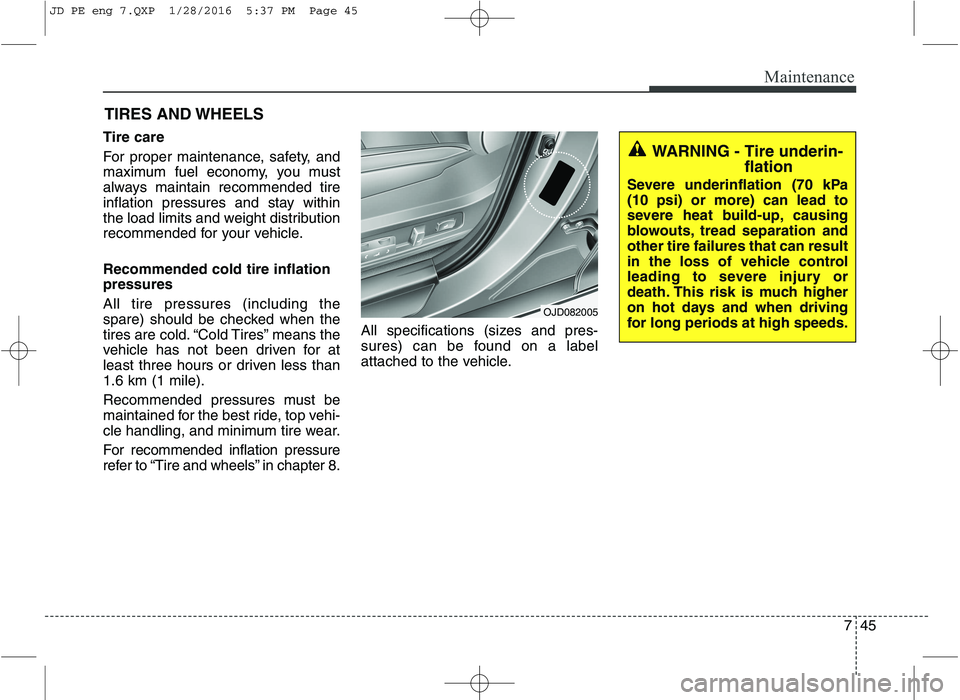
sures) can be found on a label
attached to the vehicle.
WARNING - Tire underin-
flation
Severe underinflation (70 kPa (10 psi) or more) can lead to
severe heat build-up, causing
blowouts, tread separation andother tire failures that can result
in the loss of vehicle control
leading to severe injury or
death. This risk is much higher
on hot days and when driving
for long periods at high speeds.
OJD082005
JD PE eng 7.QXP 1/28/2016 5:37 PM Page 45
Page 552 of 643

Maintenance
46
7
WARNING - Tire inflation
Overinflation or underinflation
can reduce tire life, adversely
affect vehicle handling, and
lead to sudden tire failure. This
could result in loss of vehicle
control and potential injury.
CAUTION - Tire pressure
Always observe the following:
Check tire pressure when the tires are cold. (After vehiclehas been parked for at leastthree hours or hasn't been driven more than 1.6 km (1mile) since startup.)
Check the pressure of your spare tire each time you checkthe pressure of other tires.
Never overload your vehicle. Be careful not to overload avehicle luggage rack if yourvehicle is equipped with one.
Worn, old tires can cause acci- dents. If your tread is badlyworn, or if your tires have been damaged, replace them.
CAUTION
Underinflation also results in excessive wear, poor handlingand reduced fuel economy.Wheel deformation also ispossible. Keep your tire pres-sures at the proper levels. If a tire frequently needs refilling,we recommend that the sys-tem be checked by an author- ized Kia dealer.
Overinflation produces a harsh ride, excessive wear atthe center of the tire tread, anda greater possibility of dam- age from road hazards.
CAUTION
Warm tires normally exceed recommended cold tire pres-sures by 28 to 41 kPa (4 to 6 psi). Do not release air fromwarm tires to adjust the pres-sure or the tires will be under- inflated.
Be sure to reinstall the tire inflation valve caps. Withoutthe valve cap, dirt or moisturecould get into the valve core and cause air leakage. If avalve cap is missing, install anew one as soon as possible.
JD PE eng 7.QXP 1/28/2016 5:37 PM Page 46
Page 577 of 643
771
Maintenance
SymbolRelay NameType
LOCOOLING FAN LOW RELAYPLUG MICRO
HICOOLING FAN HIGH RELAYPLUG MICRO
BLOWER RELAYPLUG MICRO
REAR DEFOGGER RELAYPLUG MICRO
4 (IG2)IG2 RELAYPLUG MICRO
FRT WIPER RELAYPLUG MICRO
3 (IG1)IG1 RELAYPLUG MICRO
1START RELAYPLUG MICRO
2 (ACC)ACC RELAYPLUG MICRO
GSLPTC
HEATERPTC RELAY (GASOLINE)PLUG MINI
Fuse ratingSymbolFuse NameRelay Name
15AF/PUMPF/PUMPFUEL PUMP RELAY
15A3ECU3ECU
15AHORNHorn Relay
10AINJECTORINJECTORINJECTOR, ECU,
FUEL PUMP RELAY
10A2ECU2ECU
20AIGN
COILIGN COILIgnition Coil #1/#2/#3/#4, Condenser
10A9SENSOR2E/R Fuse & Relay Box
(COOLING LOW RELAY),
Oil Control Valve #1/#2
20A1ECU1ECU
10A8SENSOR1Oxygen Sensor (UP/DOWN),
Variable Intake Solenoid Valve,
Purge Control Solenoid Valve
JD PE eng 7.QXP 1/28/2016 5:38 PM Page 71
Page 580 of 643
Maintenance
74
7
SymbolRelay NameType
GSL
PTC
HEATERPTC RELAY (GASOLINE)PLUG MICRO
BLOWER RELAYPLUG MICRO
REAR DEFOGGER RELAYPLUG MICRO
4 (IG2)IG2 RELAYPLUG MICRO
FRT WIPER RELAYPLUG MICRO
3 (IG1)IG1 RELAYPLUG MICRO
1START RELAYPLUG MICRO
2 (ACC)ACC RELAYPLUG MICRO
COOLING FANPLUG MINI
Fuse ratingSymbolFuse NameRelay Name
15AF/PUMPF/PUMPFUEL PUMP RELAY
15A3ECU3ECU
15AHORNHorn Relay
10AINJECTORINJECTORINJECTOR, ECU,
FUEL PUMP RELAY
10A2ECU2ECU
20AIGN
COILIGN COILIgnition Coil #1/#2/#3/#4, Condenser
10A9SENSOR2E/R Fuse & Relay Box
(COOLING LOW RELAY),
Oil Control Valve #1/#2
20A1ECU1ECU
10A8SENSOR1Oxygen Sensor (UP/DOWN),
Variable Intake Solenoid Valve,
Purge Control Solenoid Valve
JD PE eng 7.QXP 1/28/2016 5:39 PM Page 74
Page 582 of 643
Maintenance
76
7
FuseFuse ratingSymbolFuse NameProtected component
FUSE
20A5TCU1TCU
40AFUEL
HEATERFUEL HEATER RELAY
40A7EMSEMS BOX (Fuse No. - 1/2/3/4/5/6/7/8/9)
50AB+3B+3Inner Fuse Panel (Leak Current Autocut Device, Fuse No. - 6/19/20/17/32/26/25)
50ABLOWERBLOWER RELAY
10AA/CONA/C Control Module
10AWIPER FRTECU, Rain Sensor
10AB/UP
LAMPB/UP LPM/T : Back-up Lamp Switch, A/T : Transaxle Range Switch, TCU
15A4ECU4Smart Key Control Module, Immobilizer Module, ECU, Air Flow Sensor,
Fuel Water Sensor
10A3ABS3ESC Control Module, ABS Control Module, Yaw Rate Sensor
15A6TCU2Transaxle Range Switch, TCU
JD PE eng 7.QXP 1/28/2016 5:39 PM Page 76
Page 583 of 643
777
Maintenance
SymbolRelay NameType
LOCOOLING FAN LOW RELAYPLUG MICRO
HICOOLING FAN HIGH RELAYPLUG MICRO
BLOWER RELAYPLUG MICRO
REAR DEFOGGER RELAYPLUG MICRO
4 (IG2)IG2 RELAYPLUG MICRO
FRT WIPER RELAYPLUG MICRO
3 (IG1)IG1 RELAYPLUG MICRO
1START RELAYPLUG MICRO
2 (ACC)ACC RELAYPLUG MICRO
FUEL HEATER RELAYPLUG MINI
Fuse ratingSymbolFuse NameRelay Name
15ASPARESPARE-
15AHORNHORN RELAY
10A2ECU2Oil Level Sensor, Fuel
Pressure Control Valve
20ASPARESPARE-
10A9SENSOR2
E/R Fuse & Relay Box
(COOLING FAN LOW RELAY),Lambda Sensor (D4FB), Stop Lamp Switch
20A1ECU1ECU
10A8SENSOR1
DSL Box (PTC1 RELAY,
GLOW RELAY),
VGT Control Sensor,
Camshaft Position Sensor,
Electrical EGR Valve
JD PE eng 7.QXP 1/28/2016 5:39 PM Page 77