2016 JEEP WRANGLER recommended
[x] Cancel search: recommendedPage 22 of 156

Tether Anchorage Weight Limit
Always use the tether anchor when using the seat belt to install a forward facing child
restraint, up to the recommended weight limit of the child restraint.
To Install A Child Seat Using An ALR:
1. Pull enough of the seat belt webbing from the retractor to pass it through the beltpath of the child restraint. Do not twist the belt webbing in the belt path.
2. Slide the latch plate into the buckle until you hear a “click.”
3. Pull on the webbing to make the lap portion tight against the child seat.
4. To lock the seat belt, pull down on the shoulder part of the belt until you have pulled all the seat belt webbing out of the retractor. Then, allow the webbing to
retract back into the retractor. As the webbing retracts, you will hear a clicking
sound. This means the seat belt is now in the Automatic Locking mode.
5. Try to pull the webbing out of the retractor. If it is locked, you should not be able to pull out any webbing. If the retractor is not locked, repeat the last step.
6. Finally, pull up on any extra webbing to tighten the lap portion around the child restraint while you push the child restraint rearward and downward into the
vehicle seat.
7. If the child restraint has a top tether strap and the seating position has a top tether anchorage, connect the tether strap to the anchorage and tighten the tether strap.
See below for directions to attach a tether anchor.
8. Test that the child restraint is installed tightly by pulling back and forth on the child seat at the belt path. It should not move more than 1 inch (25.4 mm) in any
direction.
Installing The Top Tether Strap (With Either Lower Anchors Or Vehicle Seat
Belt):
When installing a forward-facing child restraint, always secure the top tether strap,
up to the tether anchor weight limit, whether the child restraint is installed with the
lower anchors or the vehicle seat belt.
Tether Strap Installation
1. Route the tether strap to provide the most direct path for the strap between theanchor and the child seat.
2. If your vehicle is equipped with adjustable rear head restraints, raise the head restraint, and where possible, route the tether strap under the head restraint and
between the two posts. If not possible, lower the head restraint and pass the
tether strap around the outboard side of the head restraint.
GETTING STARTED
20
Page 30 of 156

ENGINE BREAK-IN RECOMMENDATIONS
A long break-in period is not required for the engine and drivetrain (transmission and
axle) in your vehicle.
Drive moderately during the first 300 miles (500 km). After the initial 60 miles
(100 km), speeds up to 50 or 55 mph (80 or 90 km/h) are desirable.
While cruising, brief full-throttle acceleration within the limits of local traffic laws
contributes to a good break-in. Wide-open throttle acceleration in low gear can be
detrimental and should be avoided.
The engine oil installed in the engine at the factory is a high-quality energy
conserving type lubricant. Oil changes should be consistent with anticipated climate
conditions under which vehicle operations will occur. Refer to “Maintaining Your
Vehicle,” for the recommended viscosity and quality grades.
NOTE:
A new engine may consume some oil during its first few thousand miles (kilometers)
of operation. This should be considered a normal part of the break-in and not
interpreted as an indication of an engine problem or malfunction.
CAUTION!
Never use Non-Detergent Oil or Straight Mineral Oil in the engine or damage may
result.
TURN SIGNAL/LIGHTS LEVER
Headlights And Parking Lights
Turn the end of the multifunction lever to
the first detent for parking light opera-
tion. Turn to the second detent for head-
light operation.
Instrument Panel Dimmer
• Rotate the center portion of the leverto the extreme bottom position to fully
dim the instrument panel lights and
prevent the interior lights from illumi-
nating when a door is opened.
• Rotate the center portion of the lever up to increase the brightness of the
instrument panel lights when the park-
ing lights or headlights are on.
Multifunction Lever
OPERATING YOUR VEHICLE
28
Page 40 of 156

4. Grasp the header and lift the top back. Make sure the material is folded back asshown.
5. Locate the straps to secure the side bows. Wrap the straps around the bows as shown. Repeat on the other side.
6. Reposition the sun visors.
NOTE:
If you are going to be driving faster than
40 mph (64 km/h) with the Sunrider
feature open, it is recommended that you
remove the rear window of the vehicle.
• To close the Sunrider feature, perform the above steps in the opposite order.
Step 4
Step 5
OPERATING YOUR VEHICLE
38
Page 46 of 156

6. Secure the top by using the two provided straps. Each strap will wrap around theside bow and Velcro to itself; use one strap on each side of the vehicle.
NOTE:
• Failure to fold the fabric rearward will allow the material to sag and may
block the rearview mirror.
• If you are going to be driving faster than 40 mph (64 km/h) with the Sun-
rider feature open, it is recommended
that you remove the rear window of the
vehicle.
• To close the Sunrider feature, perform the above steps in the opposite order.
Four Door Soft Top Down
Follow these simple steps to lower the Four Door soft top.
1. Remove the side and back windows.
Step 6
Step 1
OPERATING YOUR VEHICLE
44
Page 103 of 156
ROADSIDE ASSISTANCE
Dial toll-free 1-800-521-2779 for U.S. Residents or 1-800-363-4869 for Canadian
Residents.
• Provide your name, vehicle identification number, license plate number, and yourlocation, including the telephone number from which you are calling.
• Briefly describe the nature of the problem and answer a few simple questions.
• You will be given the name of the service provider and an estimated time of arrival. If you feel you are in an “unsafe situation”, please let us know. With your consent,
we will contact local police or safety authorities.
INSTRUMENT CLUSTER WARNING LIGHTS
- Electronic Stability Control (ESC) Activation/Malfunction Indicator Light
If the “ESC Activation/Malfunction Indicator Light” comes on continuously with the
engine running, a malfunction has been detected in the ESC system. If this light
remains on after several ignition cycles, and the vehicle has been driven several miles
(kilometers) at speeds greater than 30 mph (48 km/h), we recommend you drive to
the nearest service center and have the vehicle serviced immediately.
The “ESC Activation/Malfunction Indicator Light” starts to flash as soon as the tires
lose traction and the ESC system becomes active. If the light begins to flash during
acceleration, ease up on the accelerator and apply as little throttle as possible. Be
sure to adapt your speed and driving to the prevailing road conditions. The light also
flashes when Traction Control System (TCS) is active. To improve the vehicle's
traction when starting off in deep snow, sand or gravel, it may be desirable to switch
the ESC system to Partial Off mode by momentarily pushing the ESC Off
switch.
– Tire Pressure Monitoring System (TPMS) Light
Each tire, including the spare (if provided), should be checked monthly when cold
and inflated to the inflation pressure recommended by the vehicle manufacturer on
the vehicle placard or tire inflation pressure label. (If your vehicle has tires of a
different size than the size indicated on the vehicle placard or tire inflation pressure
label, you should determine the proper tire inflation pressure for those tires).
As an added safety feature, your vehicle has been equipped with a tire pressure
monitoring system (TPMS) that illuminates a low tire pressure telltale when one or
more of your tires is significantly under-inflated. Accordingly, when the low tire
pressure telltale illuminates, you should stop and check your tires as soon as possible
and inflate them to the proper pressure. Driving on a significantly under-inflated tire
causes the tire to overheat and can lead to tire failure. Under-inflation also reduces
fuel efficiency and tire tread life and may affect the vehicle’s handling and stopping
ability.
WHAT TO DO IN EMERGENCIES
101
Page 117 of 156

WARNING!
Do not connect the jumper cable to the negative (-) post of the discharged battery. The
resulting electrical spark could cause the battery to explode and could result in serious
injury. Only use the specific ground point, do not use any other exposed metal parts.
5. Start the engine in the vehicle that has the booster battery, let the engine idle afew minutes, and then start the engine in the vehicle with the discharged battery.
6. Once the engine is started, remove the jumper cables in the reverse sequence:
Disconnecting The Jumper Cables
1. Disconnect the negative (-)end of the jumper cable from the engine ground of the
vehicle with the discharged battery.
2. Disconnect the opposite end of the negative (-)jumper cable from the negative (-)
post of the booster battery.
3. Disconnect the positive (+)end of the jumper cable from the positive (+)post of
the booster battery.
4. Disconnect the opposite end of the positive (+)jumper cable from the positive (+)
post of the vehicle with the discharged battery.
If frequent jump starting is required to start your vehicle you should have the battery
and charging system inspected at your authorized dealer.
CAUTION!
Accessories plugged into the vehicle power outlets draw power from the vehicle’s
battery, even when not in use (i.e., cellular devices, etc.). Eventually, if plugged in
long enough without engine operation, the vehicle’s battery will discharge suffi-
ciently to degrade battery life and/or prevent the engine from starting.
EMERGENCY TOW HOOKS — IF EQUIPPED
If your vehicle is equipped with tow hooks, they are mounted in the front and the rear.
NOTE:
For off-road recovery, it is recommended to use both of the front tow hooks to minimize the
risk of damage to the vehicle. Always use an appropriately rated tow strap.
WARNING!
• Do not use a chain for freeing a stuck vehicle. Chains may break, causing serious injury or death.
• Stand clear of vehicles when pulling with tow hooks. Tow straps may become
disengaged, causing serious injury.
WHAT TO DO IN EMERGENCIES
115
Page 118 of 156
CAUTION!
Tow hooks are for emergency use only, to rescue a vehicle stranded off road. Do not
use tow hooks for tow truck hookup or highway towing. You could damage your
vehicle. Tow straps are recommended when towing the vehicle, chains may cause
vehicle damage.
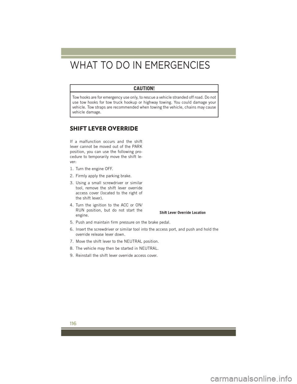
SHIFT LEVER OVERRIDE
If a malfunction occurs and the shift
lever cannot be moved out of the PARK
position, you can use the following pro-
cedure to temporarily move the shift le-
ver:
1. Turn the engine OFF.
2. Firmly apply the parking brake.
3. Using a small screwdriver or similartool, remove the shift lever override
access cover (located to the right of
the shift lever).
4. Turn the ignition to the ACC or ON/ RUN position, but do not start the
engine.
5. Push and maintain firm pressure on the brake pedal.
6. Insert the screwdriver or similar tool into the access port, and push and hold the override release lever down.
7. Move the shift lever to the NEUTRAL position.
8. The vehicle may then be started in NEUTRAL.
9. Reinstall the shift lever override access cover.
Shift Lever Override Location
WHAT TO DO IN EMERGENCIES
116
Page 127 of 156

CAUTION!
•Mixing of engine coolant (antifreeze) other than specified Organic Additive Tech-
nology (OAT) engine coolant (antifreeze), may result in engine damage and may
decrease corrosion protection. Organic Additive Technology (OAT) engine coolant is
different and should not be mixed with Hybrid Organic Additive Technology (HOAT)
engine coolant (antifreeze) or any “globally compatible” coolant (antifreeze). If a
non-OAT engine coolant (antifreeze) is introduced into the cooling system in an
emergency, the cooling system will need to be drained, flushed, and refilled with
fresh OAT coolant (conforming to MS.90032), by an authorized dealer as soon as
possible.
• Do not use water alone or alcohol-based engine coolant (antifreeze) products.Do not use additional rust inhibitors or antirust products, as they may not be
compatible with the radiator engine coolant and may plug the radiator.
• This vehicle has not been designed for use with propylene glycol-based engine
coolant (antifreeze). Use of propylene glycol-based engine coolant (antifreeze)
is not recommended.
Chassis
Component Fluid, Lubricant, or Genuine Part
Automatic Transmission – If Equipped
Use only ATF+4 Automatic Transmission
Fluid. Failure to use ATF+4 fluid may affect
the function or performance of your transmis-
sion. We recommend MOPAR ATF+4 fluid.
Manual Transmission – If EquippedWe recommend you use MOPAR Manual
Transmission Lubricant meeting the require-
ments of FCA US Material Standard MS-
9224.
Transfer Case We recommend you use MOPAR ATF+4
Automatic Transmission Fluid.
Axle Differential (Front) We recommend you use MOPAR Gear &
Axle Lubricant (SAE 80W-90) (API GL-5).
Axle Differential (Rear)
226 RBI (Model 44) – We recommend you use
MOPAR Gear & Axle Lubricant (SAE 80W-90)
(API GL-5) or equivalent. For trailer towing,
use MOPAR Synthetic Gear & Axle Lubricant
(SAE 75W-140). Models equipped with Trac-
Lok require an additive.
Brake Master Cylinder We recommend you use MOPAR DOT 3
Brake Fluid, SAE J1703. If DOT 3, SAE
J1703 brake fluid is not available, then
DOT 4 is acceptable.
Power Steering Reservoir We recommend you use MOPAR Power
Steering Fluid +4, MOPAR ATF+4 Auto-
matic Transmission Fluid.
MAINTAINING YOUR VEHICLE
125