Page 168 of 688
3. Slide out the sun visor extender for even more side
coverage toward the rear.
Power Outlets
The front power outlet is located under the center stack of
the instrument panel. It only operates with the ignition in
the MAR/RUN position.Models equipped with the optional�smoker kit,�will
have a cigar lighter instead of the power outlet. Refer to
“Cigar Lighter�in “Internal Equipment Storage” for
further information.
Using The Extender
12 Volt Power Outlet
166 GETTING TO KNOW YOUR VEHICLE
Page 175 of 688
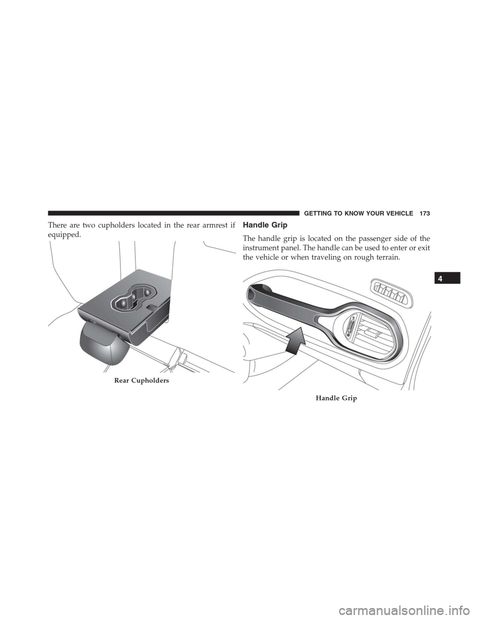
There are two cupholders located in the rear armrest if
equipped.Handle Grip
The handle grip is located on the passenger side of the
instrument panel. The handle can be used to enter or exit
the vehicle or when traveling on rough terrain.
Rear Cupholders
Handle Grip
4
GETTING TO KNOW YOUR VEHICLE 173
Page 183 of 688
Speedometer (EVIC)
Indicates the speed of the vehicle in MPH or km/h.
Adjusting Instrument Panel Illumination (Light Sen-
sor)
Inside the speedometer, a light sensor detects ambient
light conditions and adjusts the brightness of the instru-
ment cluster.
Instrument Panel Light Sensor Zone
1 — Instrument Panel Light Sensor Zone
5
GETTING TO KNOW YOUR INSTRUMENT CLUSTER 181
Page 184 of 688
The instrument works as follows:
•In�day�mode the display, the graphics, and all indexes
for the instrument cluster are fully illuminated and are
not adjustable
•In�night�mode the display, the graphics, and the
indexes are adjusted accordingly. Even the light inten-
sity of the automatic dual zone climate control system
and the Uconnect system display
Speedometer (DID)
Indicates the speed of the vehicle in MPH or km/h.
Adjusting Instrument Panel Illumination (Light Sen-
sor)
Inside the speedometer, a light sensor detects ambient
light conditions and adjusts the brightness of the instru-
ment cluster.
Instrument Panel Light Sensor Zone
1 — Instrument Panel Light Sensor Zone 182 GETTING TO KNOW YOUR INSTRUMENT CLUSTER
Page 187 of 688

WARNING!
A hot engine cooling system is dangerous. You or
others could be badly burned by steam or boiling
coolant. You may want to call an authorized dealer
for service if your vehicle overheats. If you decide to
look under the hood yourself, see “Maintaining And
Caring For Your Vehicle.” Follow the warnings under
the “Cooling System Pressure Cap” paragraph.
WARNING AND INDICATOR LIGHTS
IMPORTANT:The warning / indicator light switches on
in the instrument panel together with a dedicated mes-
sage and/or acoustic signal when applicable. These
indications are indicative and precautionary and as such
must not be considered as exhaustive and/or alternative
to the information contained in the Owner Manual,
which you are advised to read carefully in all cases.
Always refer to the information in this chapter in the
event of a failure indication.
All active telltales will display first if applicable. The
system check menu may appear different based upon
equipment options and current vehicle status. Some
telltales are optional and may not appear.
5
GETTING TO KNOW YOUR INSTRUMENT CLUSTER 185
Page 225 of 688
•OK Button
The OK button may be used for the following:
Select
Reset (hold)
EVIC/DID Main Menu
The Main Menu is composed of several options that can
be selected using the control buttons above.
NOTE:
•The display mode of the menu items varies depending
on the type of display.
•For some items, a submenu is provided.
•In the Uconnect system, some items on the menu are
not shown on the instrument panel display.Menu Items
The Menu has the following options:
•Speedometer
•Vehicle Info
•Driver Assist
•Fuel Economy
•Trip
•Audio
•Messages
•Screen Setup
•Settings5
GETTING TO KNOW YOUR INSTRUMENT CLUSTER 223
Page 236 of 688
NOTE:Keep magnetic materials away from the top of the
instrument panel, such as iPod’s, Mobile Phones, Lap-
tops, and Radar Detectors. This is where the compass
module is located, and it can cause interference with the
compass sensor, and it may give false readings.TRIP COMPUTER
The Trip computer is used to display information on car
operation when the key is turned to the MAR/RUN
position.
This function allows you to define two separate trips
called “Trip A” and “Trip B” where the car’s�complete
trips�are monitored in an independent manner.
Both trips can be reset (reset - start of a new trip). To
perform a reset, push and hold the OK button on the
steering wheel controls.
“Trip A” is used to display the figures relating to:
•Distance Travelled
•Average Consumption
•Travel Time (driving time)
•Average Speed
Compass Variance Map
234 GETTING TO KNOW YOUR INSTRUMENT CLUSTER
Page 276 of 688

WARNING!(Continued)
•Do not use the Automatic Locking Mode to restrain
occupants who are wearing the seat belt or children
who are using booster seats. The locked mode is
only used to install rear-facing or forward-facing
child restraints that have a harness for restraining
the child.
Supplemental Restraint System (SRS)
Air Bag System Components
Your vehicle may be equipped with the following air bag
system components:
•Occupant Restraint Controller (ORC)
•Air Bag Warning Light
•Steering Wheel and Column•Instrument Panel
•Knee Impact Bolsters
•Advanced Front Air Bags
•Supplemental Side Air Bags
•Supplemental Knee Air Bags
•Front and Side Impact Sensors
•Seat Belt Pretensioners
•Seat Belt Buckle Switch
•Seat Track Position Sensors
Advanced Front Air Bags
This vehicle has Advanced Front Air Bags for both the
driver and front passenger as a supplement to the seat
belt restraint systems. The driver ’s Advanced Front Air
Bag is mounted in the center of the steering wheel. The
274 SAFETY