Page 494 of 723
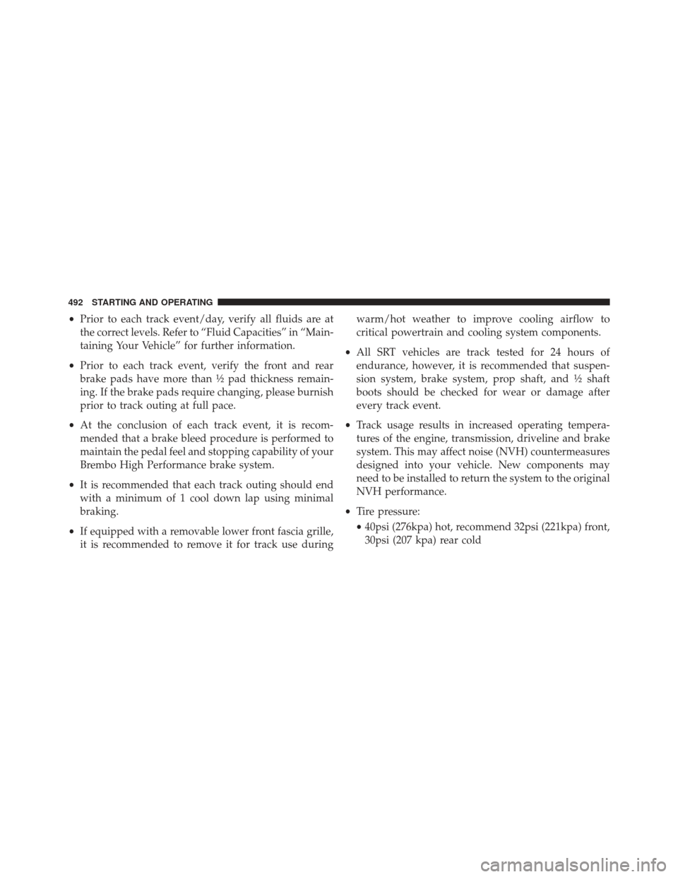
•Prior to each track event/day, verify all fluids are at
the correct levels. Refer to “Fluid Capacities” in “Main-
taining Your Vehicle” for further information.
• Prior to each track event, verify the front and rear
brake pads have more than ½ pad thickness remain-
ing. If the brake pads require changing, please burnish
prior to track outing at full pace.
• At the conclusion of each track event, it is recom-
mended that a brake bleed procedure is performed to
maintain the pedal feel and stopping capability of your
Brembo High Performance brake system.
• It is recommended that each track outing should end
with a minimum of 1 cool down lap using minimal
braking.
• If equipped with a removable lower front fascia grille,
it is recommended to remove it for track use during warm/hot weather to improve cooling airflow to
critical powertrain and cooling system components.
• All SRT vehicles are track tested for 24 hours of
endurance, however, it is recommended that suspen-
sion system, brake system, prop shaft, and ½ shaft
boots should be checked for wear or damage after
every track event.
• Track usage results in increased operating tempera-
tures of the engine, transmission, driveline and brake
system. This may affect noise (NVH) countermeasures
designed into your vehicle. New components may
need to be installed to return the system to the original
NVH performance.
• Tire pressure:
• 40psi (276kpa) hot, recommend 32psi (221kpa) front,
30psi (207 kpa) rear cold
492 STARTING AND OPERATING
Page 495 of 723
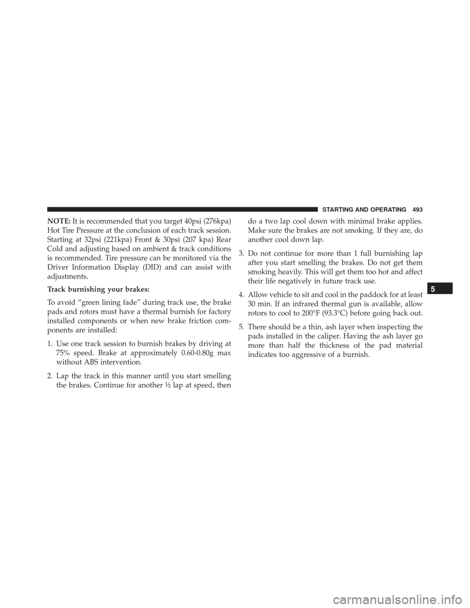
NOTE:It is recommended that you target 40psi (276kpa)
Hot Tire Pressure at the conclusion of each track session.
Starting at 32psi (221kpa) Front & 30psi (207 kpa) Rear
Cold and adjusting based on ambient & track conditions
is recommended. Tire pressure can be monitored via the
Driver Information Display (DID) and can assist with
adjustments.
Track burnishing your brakes:
To avoid “green lining fade” during track use, the brake
pads and rotors must have a thermal burnish for factory
installed components or when new brake friction com-
ponents are installed:
1. Use one track session to burnish brakes by driving at 75% speed. Brake at approximately 0.60-0.80g max
without ABS intervention.
2. Lap the track in this manner until you start smelling the brakes. Continue for another ½ lap at speed, then do a two lap cool down with minimal brake applies.
Make sure the brakes are not smoking. If they are, do
another cool down lap.
3. Do not continue for more than 1 full burnishing lap after you start smelling the brakes. Do not get them
smoking heavily. This will get them too hot and affect
their life negatively in future track use.
4. Allow vehicle to sit and cool in the paddock for at least 30 min. If an infrared thermal gun is available, allow
rotors to cool to 200°F (93.3°C) before going back out.
5. There should be a thin, ash layer when inspecting the pads installed in the caliper. Having the ash layer go
more than half the thickness of the pad material
indicates too aggressive of a burnish.
5
STARTING AND OPERATING 493
Page 524 of 723
TIRE SAFETY INFORMATION
Tire MarkingsNOTE:
•P (Passenger) — Metric tire sizing is based on U.S.
design standards. P-Metric tires have the letter “P”
molded into the sidewall preceding the size designa-
tion. Example: P215/65R15 95H.
• European — Metric tire sizing is based on European
design standards. Tires designed to this standard have
the tire size molded into the sidewall beginning with
the section width. The letter �P�is absent from this tire
size designation. Example: 215/65R15 96H.
• LT (Light Truck) — Metric tire sizing is based on U.S.
design standards. The size designation for LT-Metric
tires is the same as for P-Metric tires except for the
letters “LT” that are molded into the sidewall preced-
ing the size designation. Example: LT235/85R16.
1 — U.S. DOT Safety Standards
Code (TIN) 4 — Maximum Load
2 — Size Designation 5 — Maximum Pressure
3 — Service Description 6 — Treadwear, Traction and
Temperature Grades
522 STARTING AND OPERATING
Page 525 of 723
•Temporary spare tires are designed for temporary
emergency use only. Temporary high pressure com-
pact spare tires have the letter “T” or “S” molded into
the sidewall preceding the size designation. Example:
T145/80D18 103M. •
High flotation tire sizing is based on U.S. design
standards and it begins with the tire diameter molded
into the sidewall. Example: 31x10.5 R15 LT.
Tire Sizing Chart
EXAMPLE:
Example Size Designation: P215/65R15XL 95H, 215/65R15 96H, LT235/85R16C, T145/80D18 103M, 31x10.5 R15 LT
P = Passenger car tire size based on U.S. design standards, or
�....blank....� = Passenger car tire based on European design standards, or
LT = Light truck tire based on U.S. design standards, or
TorS= Temporary spare tire or
31 = Overall diameter in inches (in)
215, 235, 145 = Section width in millimeters (mm)
65, 85, 80 = Aspect ratio in percent (%)
– Ratio of section height to section width of tire, or
10.5 = Section width in inches (in)
5
STARTING AND OPERATING 523
Page 526 of 723
EXAMPLE:
R = Construction code
–�R� means radial construction, or
– �D� means diagonal or bias construction
15, 16, 18 = Rim diameter in inches (in)
Service Description: 95= Load Index
– A numerical code associated with the maximum load a tire can carry
H = Speed Symbol
– A symbol indicating the range of speeds at which a tire can carry a load corresponding to
its load index under certain operating conditions
– The maximum speed corresponding to the speed symbol should only be achieved under
specified operating conditions (i.e., tire pressure, vehicle loading, road conditions, and
posted speed limits)
524 STARTING AND OPERATING
Page 527 of 723
EXAMPLE:
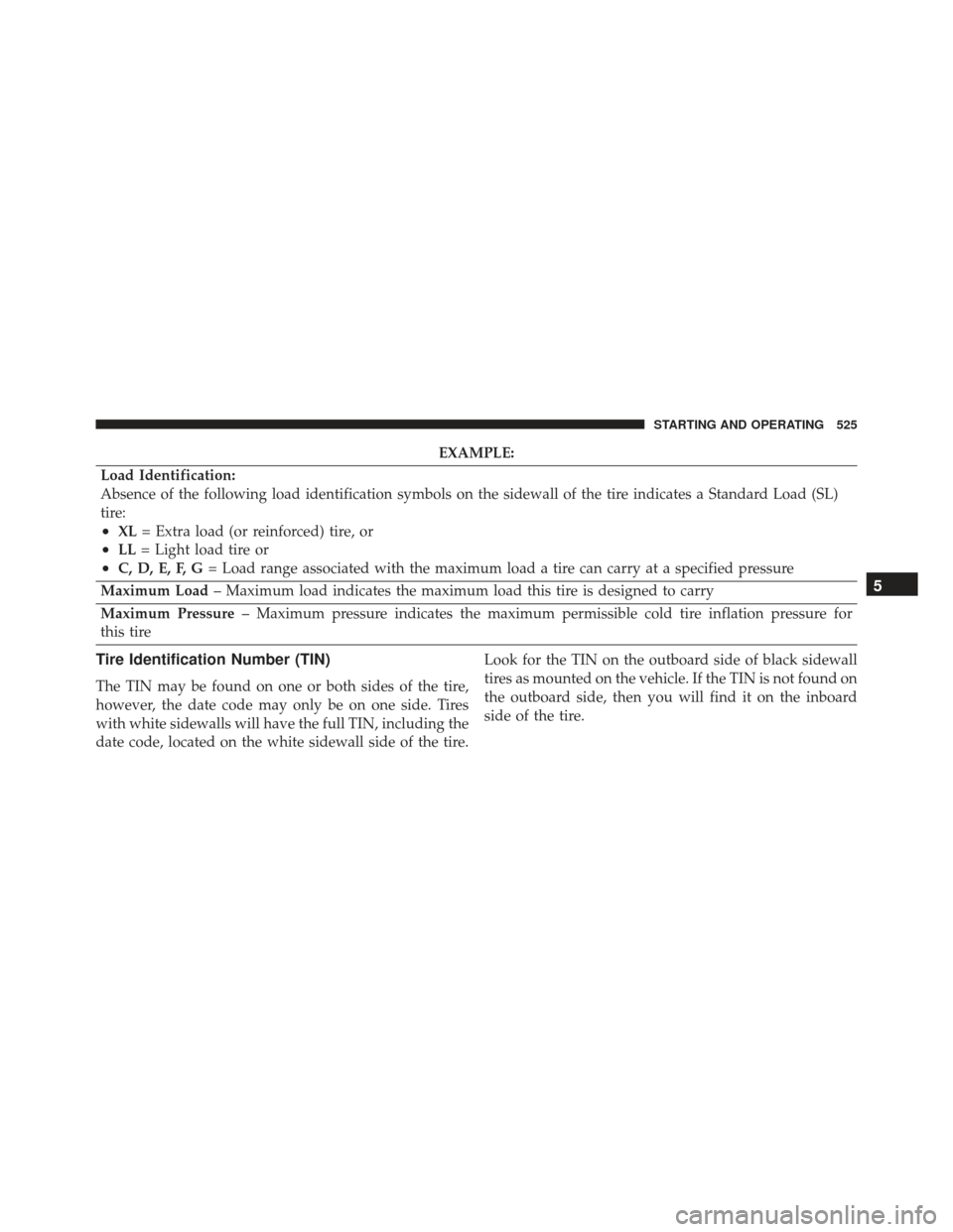
Load Identification:
Absence of the following load identification symbols on the sidewall of the tire indicates a Standard Load (SL)
tire:
•XL = Extra load (or reinforced) tire, or
•LL= Light load tire or
•C, D, E, F, G = Load range associated with the maximum load a tire can carry at a specified pressure
Maximum Load – Maximum load indicates the maximum load this tire is designed to carry
Maximum Pressure – Maximum pressure indicates the maximum permissible cold tire inflation pressure for
this tire
Tire Identification Number (TIN)
The TIN may be found on one or both sides of the tire,
however, the date code may only be on one side. Tires
with white sidewalls will have the full TIN, including the
date code, located on the white sidewall side of the tire. Look for the TIN on the outboard side of black sidewall
tires as mounted on the vehicle. If the TIN is not found on
the outboard side, then you will find it on the inboard
side of the tire.
5
STARTING AND OPERATING 525
Page 529 of 723
Tire Terminology And Definitions
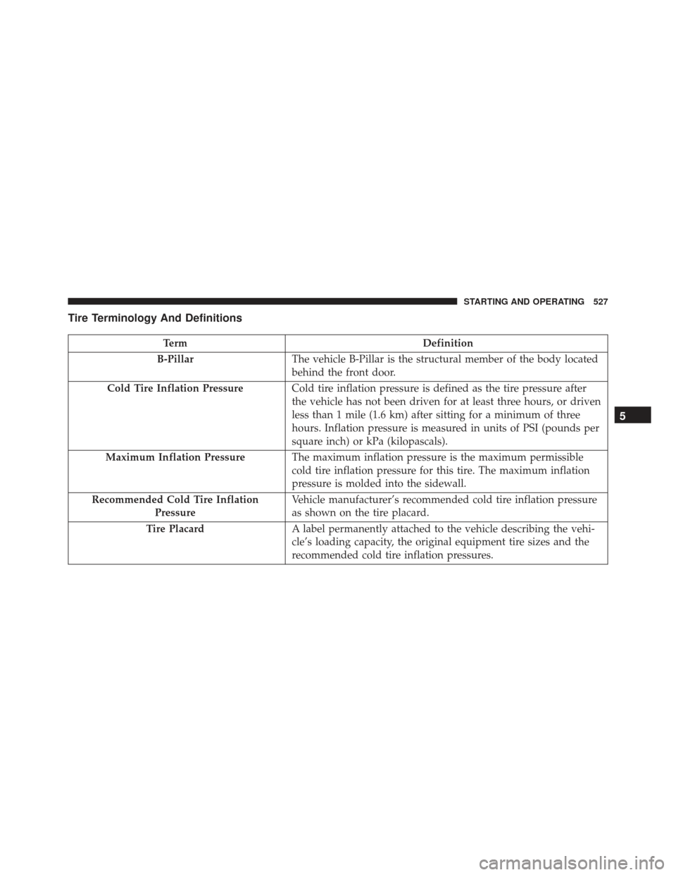
TermDefinition
B-Pillar The vehicle B-Pillar is the structural member of the body located
behind the front door.
Cold Tire Inflation Pressure Cold tire inflation pressure is defined as the tire pressure after
the vehicle has not been driven for at least three hours, or driven
less than 1 mile (1.6 km) after sitting for a minimum of three
hours. Inflation pressure is measured in units of PSI (pounds per
square inch) or kPa (kilopascals).
Maximum Inflation Pressure The maximum inflation pressure is the maximum permissible
cold tire inflation pressure for this tire. The maximum inflation
pressure is molded into the sidewall.
Recommended Cold Tire Inflation Pressure Vehicle manufacturer’s recommended cold tire inflation pressure
as shown on the tire placard.
Tire Placard A label permanently attached to the vehicle describing the vehi-
cle’s loading capacity, the original equipment tire sizes and the
recommended cold tire inflation pressures.
5
STARTING AND OPERATING 527
Page 530 of 723
Tire Loading And Tire Pressure
Tire And Loading Information Placard Location
NOTE:The proper cold tire inflation pressure is listed on
the driver ’s side B-Pillar or the rear edge of the driver’s
side door.
Example Tire Placard Location (Door)
528 STARTING AND OPERATING