Page 489 of 745
Selec-Terrain consists of the following positions:
•Snow –
Tuning set for additional stability in inclement
weather. Use on and off road on loose traction surfaces
such as snow. When in Snow mode (depending on
certain operating conditions), the transmission may use
second gear (rather than first gear) during launches, to
minimize wheel slippage. If equipped with air suspen-
sion, the default ride height for Snow is NRH.
• Auto – Fully automatic full time four-wheel drive
operation can be used on and off road. Balances
traction with seamless steering feel to provide im-
proved handling and acceleration over two-wheel
drive vehicles. If equipped with air suspension, the
level will change to NRH.
• Sand – Off road calibration for use on low traction
surfaces such as sand or wet grass. Driveline is maxi-
mized for traction. Some binding may be felt on less
forgiving surfaces. The electronic brake controls are set to limit traction control management of throttle and
wheel spin. If equipped with air suspension, the
default ride height for Sand is NRH.
• Mud – Off road calibration for use on low traction
surfaces such as mud. Driveline is maximized for
traction. Some binding may be felt on less forgiving
surfaces. The electronic brake controls are set to limit
traction control management of throttle and wheel
spin. If equipped with air suspension, the level will
change to Off Road 1.
• Rock – Off road calibration only available in 4WD Low
range. The vehicle is raised (if equipped with Air
Suspension) for improved ground clearance. Traction
based tuning with improved steer-ability for use on
high traction off-road surfaces. Use for low speed
obstacles such as large rocks, deep ruts, etc. If
equipped with air suspension, the vehicle level will
change to Off-Road 2. If the Selec-Terrain switch is in
5
STARTING AND OPERATING 487
Page 490 of 745
ROCK mode, and the transfer case is switched from
4WD Low to 4WD High, the Selec-Terrain system will
return to AUTO.
NOTE: Activate the Hill Descent Control or Selec Speed
Control for steep downhill control. See “Electronic Brake
Control System” in this section for further information.
Driver Information Display (DID) Messages
When the appropriate conditions exist, a message will
appear in the DID display. Refer to “Driver Information
Display (DID)” in “Understanding Your Instrument
Panel” for further information.
QUADRA-LIFT — IF EQUIPPED
Description
The Quadra-Lift air suspension system provides full time
load leveling capability along with the benefit of vehicle
height adjustment by the push of a button.
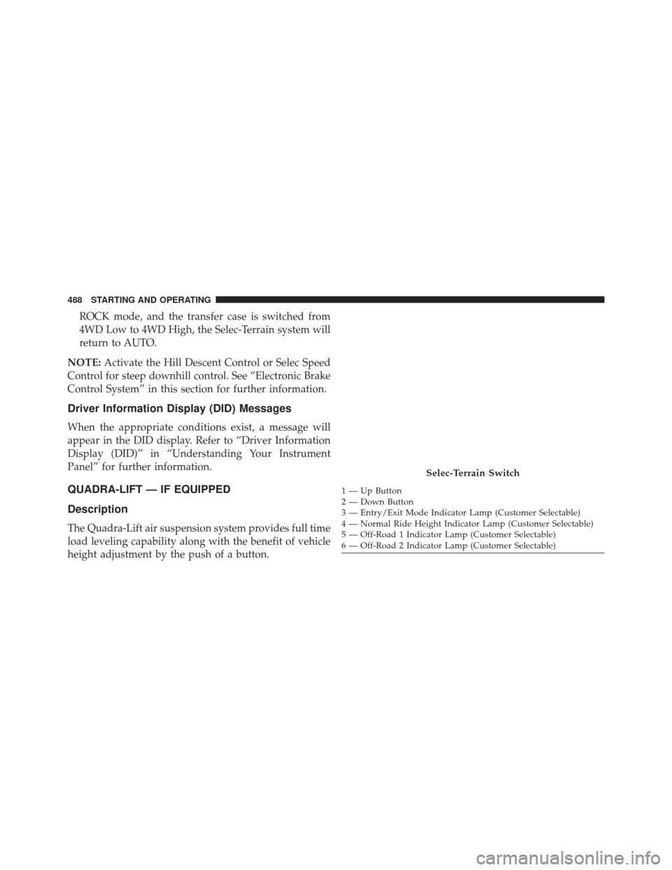
Selec-Terrain Switch
1 — Up Button
2 — Down Button
3 — Entry/Exit Mode Indicator Lamp (Customer Selectable)
4 — Normal Ride Height Indicator Lamp (Customer Selectable)
5 — Off-Road 1 Indicator Lamp (Customer Selectable)
6 — Off-Road 2 Indicator Lamp (Customer Selectable)
488 STARTING AND OPERATING
Page 494 of 745
NOTE:This mode is intended to be enabled with engine
running.
Transport Mode
To assist with flat bed towing, the air suspension system
has a feature which will put the vehicle into Entry/Exit
height and disable the automatic load leveling system.
Refer to “Uconnect Settings” in “Understanding Your
Instrument Panel” for further information.
NOTE: This mode is intended to be enabled with engine
running.
Wheel Alignment Mode
Before performing a wheel alignment this mode must be
enabled. Refer to “Uconnect Settings” in “Understanding
Your Instrument Panel” for further information.
NOTE: This mode is intended to be enabled with engine
running.If equipped with a touch screen radio all enabling/
disabling of air suspension features must be done through
the radio. Refer to “Uconnect Settings” in “Understanding
Your Instrument Panel” for further information.
Driver Information Display (DID) Messages
When the appropriate conditions exist, a message will
appear in the DID display. Refer to “Driver Information
Display (DID)” in “Understanding Your Instrument
Panel” for further information.
Operation
The indicator lamps 3 through 6 will illuminate to show
the current position of the vehicle. Flashing indicator
lamps will show a position which the system is working
to achieve. When raising, if multiple indicator lamps are
flashing on the “Up” button, the highest flashing indica-
tor lamp is the position the system is working to achieve.
492 STARTING AND OPERATING
Page 511 of 745
come on when the ignition switch is turned to the ON
position, have the light repaired as soon as possible.
Anti-Lock Brake System (ABS)
The Anti-Lock Brake System (ABS) provides increased
vehicle stability and brake performance under most
braking conditions. The system automatically prevents
wheel lock, and enhances vehicle control during braking.
The ABS performs a self-check cycle to ensure that the
ABS is working properly each time the vehicle is started
and driven. During this self-check, you may hear a slight
clicking sound as well as some related motor noises.
ABS is activated during braking when the system detects
one or more wheels begins to lock. Road conditions such
as ice, snow, gravel, bumps, railroad tracks, loose debris,
or panic stops may increase the likelihood of ABS activa-
tion(s).You also may experience the following when ABS acti-
vates:
•
The ABS motor noise (it may continue to run for a
short time after the stop).
• The clicking sound of solenoid valves.
• Brake pedal pulsations.
• A slight drop of the brake pedal at the end of the stop.
These are all normal characteristics of ABS.
WARNING!
• The ABS contains sophisticated electronic equip-
ment that may be susceptible to interference
caused by improperly installed or high output
radio transmitting equipment. This interference
(Continued)
5
STARTING AND OPERATING 509
Page 513 of 745
If the “Anti-Lock Brake Warning Light” is on, the brake
system should be serviced as soon as possible to restore
the benefits of anti-lock brakes. If the “Anti-Lock Brake
Warning Light” does not come on when the ignition
switch is turned to the ON position, have the light
repaired as soon as possible.
Brake Assist System (BAS)
The BAS is designed to optimize the vehicle’s braking
capability during emergency braking maneuvers. The
system detects an emergency braking situation by sens-
ing the rate and amount of brake application and then
applies optimum pressure to the brakes. This can help
reduce braking distances. The BAS complements the
anti-lock brake system (ABS). Applying the brakes very
quickly results in the best BAS assistance. To receive the
benefit of the system, you must apply continuous brak-
ing pressure during the stopping sequence, (do not“pump” the brakes). Do not reduce brake pedal pressure
unless braking is no longer desired. Once the brake pedal
is released, the BAS is deactivated.
WARNING!
The Brake Assist System (BAS) cannot prevent the
natural laws of physics from acting on the vehicle,
nor can it increase the traction afforded by prevailing
road conditions. BAS cannot prevent collisions, in-
cluding those resulting from excessive speed in
turns, driving on very slippery surfaces, or hydro-
planing. The capabilities of a BAS-equipped vehicle
must never be exploited in a reckless or dangerous
manner, which could jeopardize the user’s safety or
the safety of others.
5
STARTING AND OPERATING 511
Page 545 of 745
At least once a month:
•Check and adjust tire pressure with a good quality
pocket-type pressure gauge. Do not make a visual
judgement when determining proper inflation. Tires
may look properly inflated even when they are under-
inflated.
• Inspect tires for signs of tire wear or visible damage.
CAUTION!
After inspecting or adjusting the tire pressure, al-
ways reinstall the valve stem cap. This will prevent
moisture and dirt from entering the valve stem,
which could damage the valve stem.
Inflation pressures specified on the placard are always
“cold tire inflation pressure”. Cold tire inflation pressure
is defined as the tire pressure after the vehicle has not been driven for at least three hours, or driven less than
1 mile (1.6 km) after sitting for a minimum of three hours.
The cold tire inflation pressure must not exceed the
maximum inflation pressure molded into the tire side-
wall.
Check tire pressures more often if subject to a wide range
of outdoor temperatures, as tire pressures vary with
temperature changes.
Tire pressures change by approximately 1 psi (7 kPa) per
12°F (7°C) of air temperature change. Keep this in mind
when checking tire pressure inside a garage, especially in
the Winter.
Example: If garage temperature = 68°F (20°C) and the
outside temperature = 32°F (0°C) then the cold tire
inflation pressure should be increased by 3 psi (21 kPa),
which equals 1 psi (7 kPa) for every 12°F (7°C) for this
outside temperature condition.
5
STARTING AND OPERATING 543
Page 547 of 745
Tire Repair
If your tire becomes damaged, it may be repaired if it
meets the following criteria:
•The tire has not been driven on when flat.
• The damage is only on the tread section of your tire
(sidewall damage is not repairable).
• The puncture is no greater thana¼ofaninch (6 mm).
Consult an authorized tire dealer for tire repairs and
additional information.
Damaged Run Flat tires, or Run Flat tires that have
experienced a loss of pressure should be replaced imme-
diately with another Run Flat tire of identical size and
service description (Load Index and Speed Symbol).Tire Types
All Season Tires — If Equipped
All Season tires provide traction for all seasons (Spring,
Summer, Fall and Winter). Traction levels may vary
between different all season tires. All season tires can be
identified by the M+S, M&S, M/S or MS designation on
the tire sidewall. Use all season tires only in sets of four;
failure to do so may adversely affect the safety and
handling of your vehicle.
Summer Or Three Season Tires — If Equipped
Summer tires provide traction in both wet and dry
conditions, and are not intended to be driven in snow or
on ice. If your vehicle is equipped with Summer tires, be
aware these tires are not designed for Winter or cold
driving conditions. Install Winter tires on your vehicle
when ambient temperatures are less than 40°F (5°C) or if
roads are covered with ice or snow. For more informa-
tion, contact an authorized dealer.
5
STARTING AND OPERATING 545
Page 571 of 745
WARNING!(Continued)
•Guard against carbon monoxide with proper main-
tenance. Have the exhaust system inspected every
time the vehicle is raised. Have any abnormal
conditions repaired promptly. Until repaired, drive
with all side windows fully open.
ADDING FUEL
1. Push the fuel filler door release switch (located under the headlamp switch).
2. Open the fuel filler door.
Fuel Filler Door Release Switch
5
STARTING AND OPERATING 569