Page 534 of 745
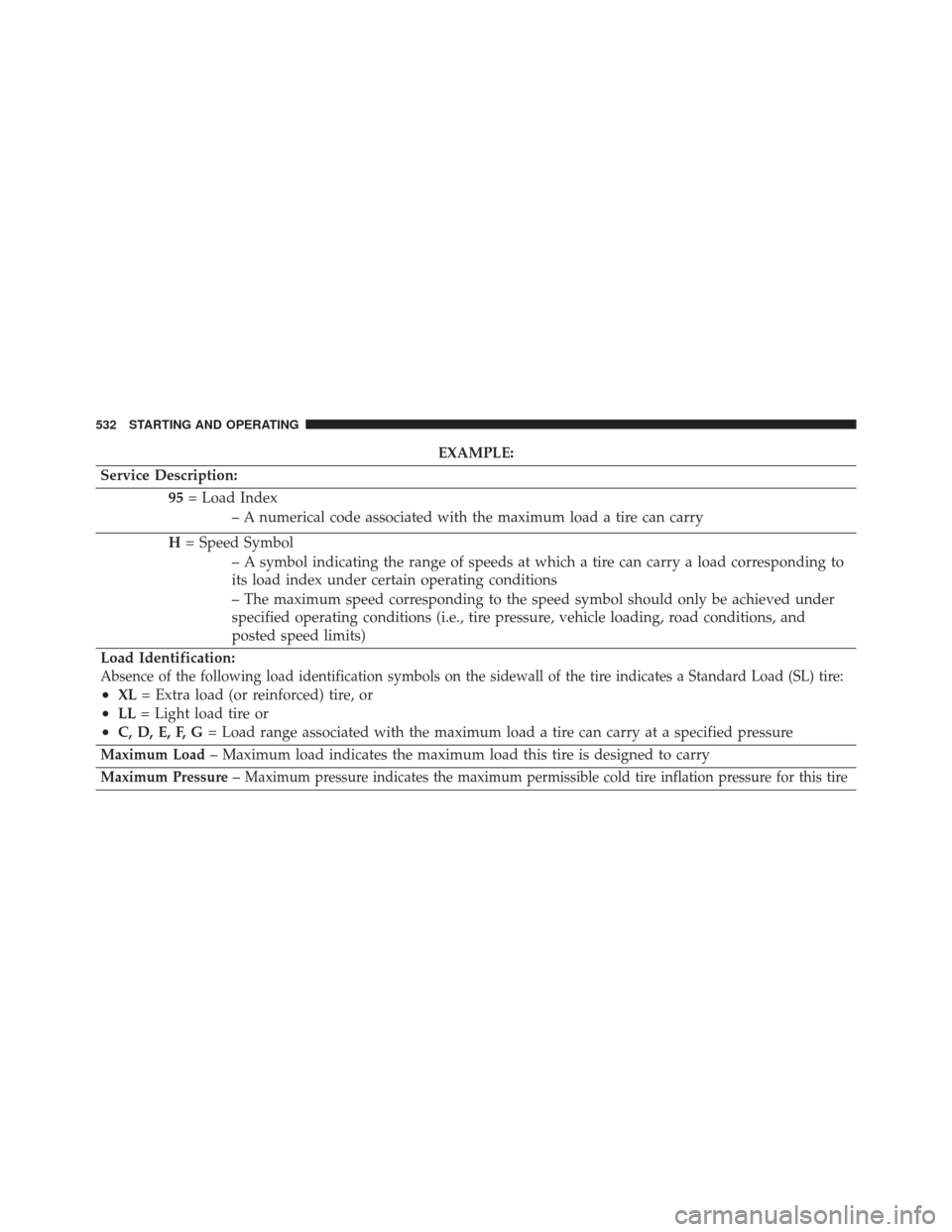
EXAMPLE:
Service Description: 95= Load Index
– A numerical code associated with the maximum load a tire can carry
H = Speed Symbol
– A symbol indicating the range of speeds at which a tire can carry a load corresponding to
its load index under certain operating conditions
– The maximum speed corresponding to the speed symbol should only be achieved under
specified operating conditions (i.e., tire pressure, vehicle loading, road conditions, and
posted speed limits)
Load Identification:
Absence of the following load identification symbols on the sidewall of the tire indicates a Standard Load (SL) tire:
•XL = Extra load (or reinforced) tire, or
•LL= Light load tire or
•C, D, E, F, G = Load range associated with the maximum load a tire can carry at a specified pressure
Maximum Load– Maximum load indicates the maximum load this tire is designed to carry
Maximum Pressure–Maximum pressure indicates the maximum permissible cold tire inflation pressure for this tire
532 STARTING AND OPERATING
Page 584 of 745
2. Pull the bottom of the cover outward (towards you),pull downwards to disengage the tabs located at the
top of the hitch receiver cover. To reinstall the hitch receiver cover after towing repeat
the procedure in reverse order.
NOTE:
Be sure to engage all tabs of the hitch receiver
cover in the bumper fascia prior to installation.
Trailer And Tongue Weight
Never exceed the maximum tongue weight stamped on
your trailer hitch.
Consider the following items when computing the
weight on the rear axle of the vehicle:
• The tongue weight of the trailer
• The weight of any other type of cargo or equipment
put in or on your vehicle
• The weight of the driver and all passengers
Hitch Receiver Cover
582 STARTING AND OPERATING
Page 646 of 745
Engine Air Cleaner Filter Installation
NOTE:Inspect and clean the housing if dirt or debris is
present before replacing the air filter element.
1. Install the air cleaner filter element into the housing assembly with the air cleaner filter inspection surface
facing downward.
2. Install the air cleaner cover onto the housing assembly locating tabs.
3. Latch the spring clips and lock the air cleaner cover to the housing assembly.
Accessory Drive Belt Inspection
WARNING!
•Do not attempt to inspect an accessory drive belt
with vehicle running.
(Continued)
WARNING! (Continued)
•When working near the radiator cooling fan, dis-
connect the fan motor lead. The fan is temperature
controlled and can start at any time regardless of
ignition switch position. You could be injured by
the moving fan blades.
• You can be badly injured working on or around a
motor vehicle. Only do service work for which you
have the knowledge and the proper equipment. If
you have any doubt about your ability to perform a
service job, take your vehicle to a competent me-
chanic.
When inspecting accessory drive belts, small cracks that
run across ribbed surface of belt from rib to rib, are
considered normal. These are not a reason to replace belt.
However, cracks running along a rib (not across) are not
644 MAINTAINING YOUR VEHICLE
Page 653 of 745
pulling the door outward. Unhinge the filter cover on
the right side to fully remove the cover.6. Remove the A/C air filter by pulling it straight out of
the housing.
7.
Install the A/C air filter with the arrow on the filter
pointing toward the floor. When installing the filter cover,
make sure the retaining tabs fully engage the cover.
CAUTION!
The A/C air filter is identified with an arrow to
indicate airflow direction through the filter. Failure
to properly install the filter will result in the need to
replace it more often.
8. Reinstall the glove compartment door on the glove compartment door hinge and reattach the glove com-
partment tension tether by inserting the tether clip in
the glove compartment and sliding the clip away from
the face of the glove compartment door.
9. Push the door to the near closed position to reengage the glove compartment travel stops.
A/C Air Filter Cover
1 — Retaining Tab
2 — Mid Way Snap
3 — Filter Cover Hinge
7
MAINTAINING YOUR VEHICLE 651
Page 671 of 745
Fluid Level Check — Brake Master Cylinder
The fluid level of the master cylinder should be checked
when performing under the hood service, or immedi-
ately if the brake system warning lamp indicates system
failure.
The brake master cylinder has a plastic reservoir. On the
outboard side of the reservoir, there is a “MAX” mark
and a “MIN” mark. The fluid level must be kept within
these two dots. Do not add fluid above the MAX mark,
because leakage may occur at the cap.
With disc brakes, the fluid level can be expected to fall as
the brake linings wear. However, an unexpected drop in
fluid level may be caused by a leak and a system check
should be conducted.
Refer to “Fluids, Lubricants, and Genuine Parts” in
“Maintaining Your Vehicle” for further information.
WARNING!
•Use only manufacturer’s recommended brake
fluid. Refer to “Fluids, Lubricants, And Genuine
Parts” in “Maintaining Your Vehicle” for further
information. Using the wrong type of brake fluid
can severely damage your brake system and/or
impair its performance. The proper type of brake
fluid for your vehicle is also identified on the
original factory installed hydraulic master cylinder
reservoir.
• To avoid contamination from foreign matter or
moisture, use only new brake fluid or fluid that has
been in a tightly closed container. Keep the master
cylinder reservoir cap secured at all times. Brake
fluid in a open container absorbs moisture from the
(Continued)
7
MAINTAINING YOUR VEHICLE 669
Page 696 of 745
CAUTION!(Continued)
•Always use the correct bulb size and type for
replacement. An incorrect bulb size or type may
overheat and cause damage to the lamp, the socket
or the lamp wiring.
4. Align the index tabs of the front fog lamp bulb with the slots in the collar of the bulb opening on the back
of the front fog lamp housing.
5. Insert the bulb into the housing until the index tabs are engaged in the slots of the collar.
6. Firmly and evenly push the bulb straight into the lamp housing until both tabs snap firmly into place and are
fully engaged.
7. Connect the wiring harness to the front fog lamp connector.
Rear Tail, Stop, and Turn Signal Lamps
1. Raise the liftgate.
2. Remove the two push-pins from the tail lamp housing.
3. Grasp the tail lamp and pull firmly rearward todisengage the lamp from the aperture panel.
Tail Lamp Push Pins
694 MAINTAINING YOUR VEHICLE
Page 716 of 745
Warranty expires. The manufacturer stands behind only
the manufacturer’s service contracts. If you purchased a
manufacturer’s service contract, you will receive Plan
Provisions and an Owner Identification Card in the mail
within three weeks of the vehicle delivery date. If you
have any questions about the service contract, call the
manufacturer’s Service Contract National Customer
Hotline at 1-800-521-9922 (Canadian residents, call (800)
465-2001 English / (800) 387-9983 French).
The manufacturer will not stand behind any service
contract that is not the manufacturer’s service contract.
It is not responsible for any service contract other than
the manufacturer’s service contract. If you purchased a
service contract that is not a manufacturer’s service
contract, and you require service after the manufacturer’s
New Vehicle Limited Warranty expires, please refer to the
contract documents, and contact the person listed in
those documents.We appreciate that you have made a major investment
when you purchased the vehicle. An authorized dealer
has also made a major investment in facilities, tools, and
training to assure that you are absolutely delighted with
the ownership experience. You will be pleased with their
sincere efforts to resolve any warranty issues or related
concerns.
WARNING!
Engine exhaust (internal combustion engines only),
some of its constituents, and certain vehicle compo-
nents contain, or emit, chemicals known to the State
of California to cause cancer and birth defects, or
other reproductive harm. In addition, certain fluids
contained in vehicles and certain products of compo-
nent wear contain, or emit, chemicals known to the
State of California to cause cancer and birth defects,
or other reproductive harm.
714 IF YOU NEED CONSUMER ASSISTANCE
Page 725 of 745
Alarm System (Security Alarm)................20
Alterations/Modifications, Vehicle ...............9
Antifreeze (Engine Coolant) ...............663, 698
Disposal ............................. .666
Anti-Lock Brake System (ABS) ................509
Anti-Lock Warning Light ....................320
Appearance Care ........................ .674
Arming System (Security Alarm) ...............20
Assist, Hill Start ......................... .512
Auto Down Power Windows ..................44
Automatic Door Locks ......................35
Automatic Headlights ..................... .170
Automatic High Beams .....................171
Automatic Temperature Control (ATC) .......417, 426
Automatic Transmission .................469, 673
Adding Fluid ......................... .673
Fluid And Filter Changes ..................673
Fluid Change ......................... .673
Fluid Level Check ...................672, 673 Fluid Type
........................ .672, 701
Gear Ranges .......................... .470
Special Additives ...................... .672
Auxiliary Electrical Outlet (Power Outlet) ........271
Auxiliary Power Outlet .....................271
Axle Fluid ............................. .701
Battery ............................ .308, 646
Charging System Light ...................308
Keyless Transmitter Replacement (RKE) ........26
Belts, Seat ...............................112
Blind Spot Monitoring ..................... .135
Body Mechanism Lubrication .................652
B-Pillar Location ......................... .536
Brake Assist System ........................511
Brake Control System, Electronic ..............508
Brake Fluid ......................... .669, 701
Brake System ........................ .507, 668
Anti-Lock (ABS) ....................... .507
10
INDEX 723
Page:
< prev 1-8 9-16 17-24