Page 628 of 745

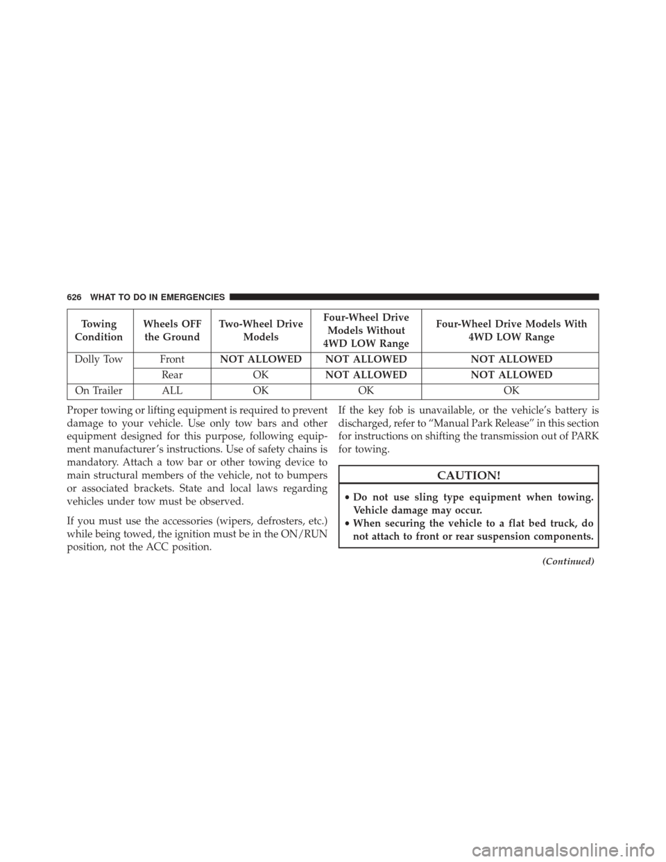
Towing
Condition Wheels OFF
the Ground Two-Wheel Drive
Models Four-Wheel Drive
Models Without
4WD LOW Range Four-Wheel Drive Models With
4WD LOW Range
Dolly Tow Front NOT ALLOWED NOT ALLOWED NOT ALLOWED
Rear OKNOT ALLOWED NOT ALLOWED
On Trailer ALL OKOK OK
Proper towing or lifting equipment is required to prevent
damage to your vehicle. Use only tow bars and other
equipment designed for this purpose, following equip-
ment manufacturer ’s instructions. Use of safety chains is
mandatory. Attach a tow bar or other towing device to
main structural members of the vehicle, not to bumpers
or associated brackets. State and local laws regarding
vehicles under tow must be observed.
If you must use the accessories (wipers, defrosters, etc.)
while being towed, the ignition must be in the ON/RUN
position, not the ACC position. If the key fob is unavailable, or the vehicle’s battery is
discharged, refer to “Manual Park Release” in this section
for instructions on shifting the transmission out of PARK
for towing.
CAUTION!
•
Do not use sling type equipment when towing.
Vehicle damage may occur.
• When securing the vehicle to a flat bed truck, do
not attach to front or rear suspension components.
(Continued)
626 WHAT TO DO IN EMERGENCIES
Page 637 of 745

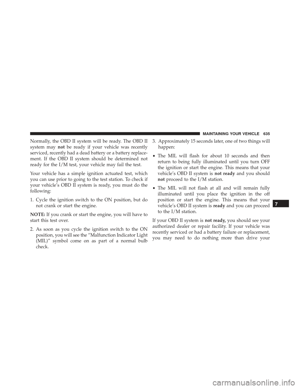
Normally, the OBD II system will be ready. The OBD II
system maynotbe ready if your vehicle was recently
serviced, recently had a dead battery or a battery replace-
ment. If the OBD II system should be determined not
ready for the I/M test, your vehicle may fail the test.
Your vehicle has a simple ignition actuated test, which
you can use prior to going to the test station. To check if
your vehicle’s OBD II system is ready, you must do the
following:
1. Cycle the ignition switch to the ON position, but do not crank or start the engine.
NOTE: If you crank or start the engine, you will have to
start this test over.
2. As soon as you cycle the ignition switch to the ON position, you will see the “Malfunction Indicator Light
(MIL)” symbol come on as part of a normal bulb
check. 3. Approximately 15 seconds later, one of two things will
happen:
• The MIL will flash for about 10 seconds and then
return to being fully illuminated until you turn OFF
the ignition or start the engine. This means that your
vehicle’s OBD II system is not readyand you should
not proceed to the I/M station.
• The MIL will not flash at all and will remain fully
illuminated until you place the ignition in the off
position or start the engine. This means that your
vehicle’s OBD II system is readyand you can proceed
to the I/M station.
If your OBD II system is not ready,you should see your
authorized dealer or repair facility. If your vehicle was
recently serviced or had a battery failure or replacement,
you may need to do nothing more than drive your
7
MAINTAINING YOUR VEHICLE 635
Page 646 of 745

Engine Air Cleaner Filter Installation
NOTE:Inspect and clean the housing if dirt or debris is
present before replacing the air filter element.
1. Install the air cleaner filter element into the housing assembly with the air cleaner filter inspection surface
facing downward.
2. Install the air cleaner cover onto the housing assembly locating tabs.
3. Latch the spring clips and lock the air cleaner cover to the housing assembly.
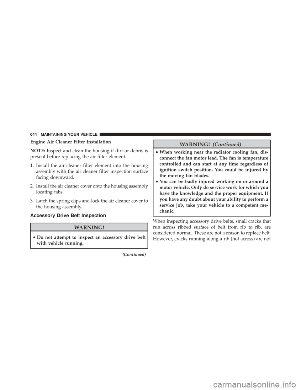
Accessory Drive Belt Inspection
WARNING!
•Do not attempt to inspect an accessory drive belt
with vehicle running.
(Continued)
WARNING! (Continued)
•When working near the radiator cooling fan, dis-
connect the fan motor lead. The fan is temperature
controlled and can start at any time regardless of
ignition switch position. You could be injured by
the moving fan blades.
• You can be badly injured working on or around a
motor vehicle. Only do service work for which you
have the knowledge and the proper equipment. If
you have any doubt about your ability to perform a
service job, take your vehicle to a competent me-
chanic.
When inspecting accessory drive belts, small cracks that
run across ribbed surface of belt from rib to rib, are
considered normal. These are not a reason to replace belt.
However, cracks running along a rib (not across) are not
644 MAINTAINING YOUR VEHICLE
Page 651 of 745
Air Conditioning Filter Replacement (A/C Air Filter)
Refer to the “Maintenance Schedule” for the proper
maintenance intervals.
WARNING!
Do not remove the A/C air filter while the vehicle is
running, or while the ignition is in the ACC or
ON/RUN mode. With the A/C air filter removed and
the blower operating, the blower can contact hands
and may propel dirt and debris into your eyes,
resulting in personal injury.
The A/C air filter is located in the fresh air inlet behind
the glove compartment. Perform the following procedure
to replace the filter:
1. Open the glove compartment and remove all contents.
Glove Compartment
1 — Glove Compartment Travel Stops
2 — Glove Compartment Tension Tether
3 — Glove Compartment Door
7
MAINTAINING YOUR VEHICLE 649
Page 664 of 745

In unusual situations involving grossly malfunctioning
engine operation, a scorching odor may suggest severe
and abnormal catalyst overheating. If this occurs, stop
the vehicle, turn off the engine and allow it to cool.
Service, including a tune-up to manufacturer’s specifica-
tions, should be obtained immediately.
To minimize the possibility of catalytic converter dam-
age:
•Do not shut off the engine or interrupt the ignition,
when the transmission is in gear and the vehicle is in
motion.
• Do not try to start the engine by pushing or towing the
vehicle.
• Do not idle the engine with any spark plug wires
disconnected or removed, such as when diagnostic
testing, or for prolonged periods during very rough
idle or malfunctioning operating conditions.Cooling System
WARNING!
You or others can be badly burned by hot engine
coolant (antifreeze) or steam from your radiator. If
you see or hear steam coming from under the hood,
do not open the hood until the radiator has had time
to cool. Never try to open a cooling system pressure
cap when the radiator or coolant bottle is hot.
Engine Coolant Checks
Check the engine coolant (antifreeze) protection every 12
months (before the onset of freezing weather, where
applicable). If the engine coolant (antifreeze) is dirty, the
system should be drained, flushed, and refilled with
fresh OAT coolant (conforming to MS.90032) by an
authorized dealer. Check the front of the A/C condenser
662 MAINTAINING YOUR VEHICLE
Page 682 of 745

WARNING!
A frayed or torn belt could rip apart in a collision and
leave you with no protection. Inspect the belt system
periodically, checking for cuts, frays, or loose parts.
Damaged parts must be replaced immediately. Do
not disassemble or modify the system. Seat belt
assemblies must be replaced after a collision if they
have been damaged (i.e., bent retractor, torn web-
bing, etc.).
FUSES
WARNING!
•When replacing a blown fuse, always use an ap-
propriate replacement fuse with the same amp
rating as the original fuse. Never replace a fuse
(Continued)
WARNING! (Continued)
with another fuse of higher amp rating. Never
replace a blown fuse with metal wires or any other
material. Failure to use proper fuses may result in
serious personal injury, fire and/or property dam-
age.
• Before replacing a fuse, make sure that the ignition
is off and that all the other services are switched off
and/or disengaged.
• If the replaced fuse blows again, contact an autho-
rized dealer.
• If a general protection fuse for safety systems (air
bag system, braking system), power unit systems
(engine system, gearbox system) or steering system
blows, contact an authorized dealer.
680 MAINTAINING YOUR VEHICLE
Page 686 of 745
CavityCartridge Fuse Micro Fuse Description
F39 30 Amp Pink –Power Liftgate - If Equipped
F40 –10 Amp Red Daytime Running Lights/Headlamp
Leveling
F42 –20 Amp Yellow Horn
F44 –10 Amp Red Diagnostic Port
F49 –10 Amp Red Integrated Central Stack / Climate Control
F50 –20 Amp Yellow Air Suspension Control Module -
If Equipped
F51 –15 Amp Blue Ignition Node Module / Keyless
Ignition / Steering Column Lock
F52 –5 Amp Tan Battery Sensor
F53 –20 Amp Yellow Trailer Tow – Left Turn/Stop Lights -
If Equipped
F56 –15 Amp Blue Additional Content (Diesel engine only)
F57 –20 Amp Yellow NOX Sensor
684 MAINTAINING YOUR VEHICLE
Page 687 of 745
CavityCartridge Fuse Micro Fuse Description
F58 –15 Amp Blue HID Headlamps LH - If Equipped
F59 –10 Amp Red Purging Pump (Diesel engine only)
F60 –15 Amp Blue Transmission Control Module
F61 –10 Amp Red Transmission Control Module/PM Sensor
(Diesel engine only)
F62 –10 Amp Red Air Conditioning Clutch
F63 –20 Amp Yellow Ignition Coils (Gas), Urea Heater (Diesel)
F64 –25 Amp Clear Fuel Injectors / Powertrain
F66 –10 Amp Red Sunroof / Passenger Window Switches /
Rain Sensor
F67 –15 Amp Blue CD / DVD / Bluetooth Hands-free
Module - If Equipped
F68 –20 Amp Yellow Rear Wiper Motor
F69 –15 Amp Blue Spotlight Feed - If Equipped
F70 –20 Amp Yellow Fuel Pump Motor
7
MAINTAINING YOUR VEHICLE 685