Page 156 of 406
479
Features of your vehicle
• The sensing distance while the rear
parking assist system is in operation is
approximately 120 cm (47 in.).
• When more than two objects are
sensed at the same time, the closest
one will be recognized first.Types of warning sound
• When an object is 120 cm to 81 cm (47
in. to 32 in.) from the rear bumper:
Buzzer beeps intermittently
• When an object is 80 cm to 41 cm (31
in. to 16 in.) from the rear bumper:
Buzzer beeps more frequently
• When an object is within 40 cm (15 in.)
of the rear bumper:
Buzzer sounds continuously.
Non-operational conditions of
rear parking assist system
The rear parking assist system may
not operate properly when:
1. Moisture is frozen to the sensor. (It will
operate normally when the moisture
has been cleared.)
2. The sensor is covered with foreign
matter, such as snow or water, or the
sensor cover is blocked. (It will operate
normally when the material is removed
or the sensor is no longer blocked.)
3. Driving on uneven road surfaces
(unpaved roads, gravel, bumps, gradi-
ent).
4. Objects generating excessive noise
(vehicle horns, loud motorcycle
engines, or truck air brakes) are within
range of the sensor.
5. Heavy rain or water spray exists.
6. Wireless transmitters or mobile
phones are within range of the sensor.
7. Trailer towing.
Page 209 of 406
5
Before driving / 5-3
Key position / 5-5
Engine start/stop button / 5-8
Manual transaxle / 5-13
Automatic transaxle / 5-16
EcoShift dual clutch transmission (For GDI) / 5-23
EcoShift dual clutch transmission (For T-GDI) / 5-31
Brake system / 5-40
Cruise control system / 5-51
Active ECO system / 5-55
Economical operation / 5-56
Special driving conditions / 5-58
Winter driving / 5-62
Vehicle load limit / 5-65
Vehicle weight / 5-70
Trailer towing / 5-70
Driving your vehicle
Page 274 of 406
Driving your vehicle
66 5
Seating capacity:
Total : 4 persons
(Front seat : 2 persons,
Rear seat : 2 persons)
Seating capacity is the maximum
number of occupants including a
driver, your vehicle may carry.
However, the seating capacity may
be reduced based upon the weight of
all of the occupants, and the weight
of the cargo being carried.
Do not overload the vehicle as there
is a limit to the total weight, or load
limit including occupants and cargo,
the vehicle can carry.
Towing capacity:
We do not recommend using this
vehicle for trailer towing.
Cargo capacity:
The cargo capacity of your vehicle
will increase or decrease depending
on the weight and the number of
occupants.
Steps For Determining Correct Load
Limit -
1. Locate the statement "The com-
bined weight of occupants and
cargo should never exceed XXX
kg or XXX lbs.'' on your vehicle's
placard.
2. Determine the combined weight of
the driver and passengers that will
be riding in your vehicle.
3. Subtract the combined weight of
the driver and passengers from
XXX kg or XXX lbs.
4. The resulting figure equals the
available amount of cargo and lug-
gage load capacity. For example, if
the "XXX" amount equals 635 kg
(1400 lbs.) and there will be five 68
kg (150 lbs.) passengers in your
vehicle, the amount of available
cargo and luggage load capacity
is 295 kg (650 lbs.).
(635-272 (4 x 68) = 363 kg or
1400-600 (4 x 150) = 800 lbs.)5. Determine the combined weight of
luggage and cargo being loaded
on the vehicle. That weight may
not safely exceed the available
cargo and luggage load capacity
calculated in Step 4.
6. If your vehicle will be towing a trail-
er, load from your trailer will be
transferred to your vehicle. Consult
this manual to determine how this
reduces the available cargo and
luggage load capacity of your
vehicle.
✽NOTICE
We do not recommend using this
vehicle for trailer towing.
Page 278 of 406
This section will guide you in the proper
loading of your vehicle, to keep your
loaded vehicle weight within its design
rating capability. Properly loading your
vehicle will provide maximum return of
the vehicle design performance. Before
loading your vehicle, familiarize yourself
with the following terms for determining
your vehicle's weight ratings, from the
vehicle's specifications and the certifica-
tion label:
Base curb weight
This is the weight of the vehicle including
a full tank of fuel and all standard equip-
ment. It does not include passengers,
cargo, or optional equipment.
Vehicle curb weight
This is the weight of your new vehicle
when you picked it up from your dealer
plus any aftermarket equipment.
Cargo weight
This figure includes all weight added to
the Base Curb Weight, including cargo
and optional equipment.GAW (Gross axle weight)
This is the total weight placed on each
axle (front and rear) - including vehicle
curb weight and all payload.
GAWR (Gross axle weight rating)
This is the maximum allowable weight
that can be carried by a single axle (front
or rear). These numbers are shown on
the certification label.
The total load on each axle must never
exceed its GAWR.
GVW (Gross vehicle weight)
This is the Base Curb Weight plus actual
Cargo Weight plus passengers.
GVWR (Gross vehicle weight rating)
This is the maximum allowable weight of
the fully loaded vehicle (including all
options, equipment, passengers and
cargo). The GVWR is shown on the cer-
tification label located on the driver’s
door sill.
We do not recommend using this
vehicle for trailer towing.
VEHICLE WEIGHTTRAILER TOWING
570
Driving your vehicle
Page 279 of 406
6
Road warning / 6-2
In case of an emergency while driving / 6-3
If the engine will not start / 6-4
Emergency starting / 6-5
If the engine overheats / 6-7
Tire pressure monitoring system (TPMS) / 6-8
If you have a flat tire (with spare tire) / 6-13
If you have a flat tire (with tire mobility kit) / 6-21
Towing / 6-27
Basic troubleshooting guide / 6-31
What to do in an emergency
Page 283 of 406

65
What to do in an emergency
EMERGENCY STARTING
Connect cables in numerical order and
disconnect in reverse order.
Jump starting
Jump starting can be dangerous if done
incorrectly. Therefore, to avoid harm to
yourself or damage to your vehicle or
battery, follow the jump starting proce-
dures. If in doubt, we strongly recom-
mend that you have a competent techni-
cian or towing service jump start your
vehicle.
CAUTION
Use only a 12-volt jumper system.
You can damage a 12-volt starting
motor, ignition system, and other
electrical parts beyond repair by
use of a 24-volt power supply (either
two 12-volt batteries in series or a
24-volt motor generator set).
WARNING- Battery
• Keep all flames or sparks away
from the battery. The battery pro-
duces hydrogen gas which may
explode if exposed to flame or
sparks.
If these instructions are not fol-
lowed exactly, serious personal
injury and damage to the vehicle
may occur! If you are not sure
how to follow this procedure,
seek qualified assistance.
Automobile batteries contain sul-
furic acid. This is poisonous and
highly corrosive. When jump
starting, wear protective glasses
and be careful not to get acid on
yourself, your clothing or on the
car.
• Do not attempt to jump start the
vehicle if the discharged battery
is frozen or if the electrolyte level
is low; the battery may rupture or
explode.
WARNING- Battery
Never attempt to check the elec-
trolyte level of the battery as this
may cause the battery to rupture or
explode causing serious injury.
1VQA4001
Jumper
terminal
Jumper Cables
Booster
battery
Page 303 of 406
625
What to do in an emergency
Distributing the sealant
11. Immediately drive approximately
7~10km (4~6miles or, about
10min) to evenly distribute the
sealant in the tire.
Do not exceed a speed of 80 km/h
(50 mph). If possible, do not fall
below a speed of 20 km/h (12 mph).
While driving, if you experience any
unusual vibration, ride disturbance or
noise, reduce your speed and drive
with caution until you can safely pull
off of the side of the road.
Call for road side service or towing.
When you use the Tire Mobility Kit,
the tire pressure sensors and wheel
may be damaged by sealant, remove
the sealant stained with tire pressure
sensors and wheel and inspect in
authorized dealer.Checking the tire inflation pres-
sure
1.After driving approximately 7~10km
(4~6miles or about 10min), stop at
a safety location.
2.Connect connection hose (9) of the
compressor directly to the tire
valve.
3.Plug the compressor power cord
into the vehicle power outlet.
4.Adjust the tire inflation pressure to
the recomended tire inflation.
With the ignition swithched on, pro-
ceed as follows.
- To increase the inflation pres-
sure :Switch on the compressor,
position I. To check the current
inflation pressure setting, briefly
switch off the compressor.✽NOTICE
The pressure gauge may show high-
er than actual reading when the
compressor is running. To get an
accurate tire pressure, the compres-
sor needs to be turned off.
- To reduce the inflation pres-
sure:Press the button (8) on the
compressor.
Page 305 of 406
627
What to do in an emergency
TOWING
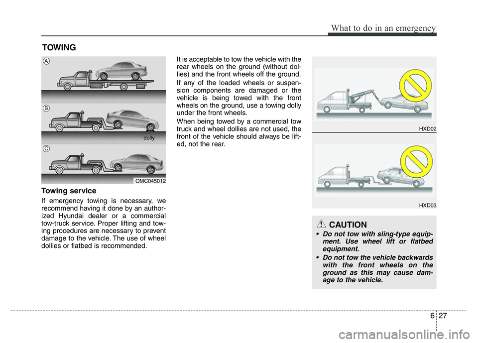
Towing service
If emergency towing is necessary, we
recommend having it done by an author-
ized Hyundai dealer or a commercial
tow-truck service. Proper lifting and tow-
ing procedures are necessary to prevent
damage to the vehicle. The use of wheel
dollies or flatbed is recommended.It is acceptable to tow the vehicle with the
rear wheels on the ground (without dol-
lies) and the front wheels off the ground.
If any of the loaded wheels or suspen-
sion components are damaged or the
vehicle is being towed with the front
wheels on the ground, use a towing dolly
under the front wheels.
When being towed by a commercial tow
truck and wheel dollies are not used, the
front of the vehicle should always be lift-
ed, not the rear.
OMC045012dolly
A
B
C
CAUTION
• Do not tow with sling-type equip-
ment. Use wheel lift or flatbed
equipment.
• Do not tow the vehicle backwards
with the front wheels on the
ground as this may cause dam-
age to the vehicle.
HXD02
HXD03