Page 573 of 642

7-60
Maintenance
Pneumatic tire
A mechanical device made of rubber,
chemicals, fabric and steel or other
materials, that, when mounted on an
automotive wheel provides the trac-tion and contains the gas or fluid thatsustains the load.
Pneumatic options weight
The combined weight of installed
regular production options weighing
over 5 lb. (2.3 kg) in excess of the
standard items which they replace,
not previously considered in curb
weight or accessory weight, includ-
ing heavy duty breaks, ride levelers,
roof rack, heavy duty battery, and
special trim.
Recommended InflationPressure
Vehicle manufacturer’s recommend-
ed tire inflation pressure as shownon the tire placard.
Radial Ply Tire
A pneumatic tire in which the ply
cords that extend to the beads are
laid at 90 degrees to the centerline ofthe tread.
Rim
A metal support for a tire and uponwhich the tire beads are seated.
Sidewall
The portion of a tire between thetread and the bead.
Speed Rating
An alphanumeric code assigned to a
tire indicating the maximum speed at
which a tire can operate.
Traction
The friction between the tire and the
road surface. The amount of grip pro-vided.
Tread
The portion of a tire that comes intocontact with the road.
Treadwear Indicators
Narrow bands, sometimes called
"wear bars", that show across thetread of a tire when only 1/16 inch of
tread remains.
UTQGS
Uniform Tire Quality Grading
Standards is a tire information sys-
tem that provides consumers with
ratings for a tire’s traction, tempera-
ture and treadwear. Ratings are
determined by tire manufacturers
using government testing proce-
dures. The ratings are molded into
the sidewall of the tire.
Vehicle Capacity Weight
The number of designated seating
positions multiplied by 150 lbs. (68
kg) plus the rated cargo and luggageload.
Page 577 of 642

7-64
Maintenance
FFUU SSEE SS
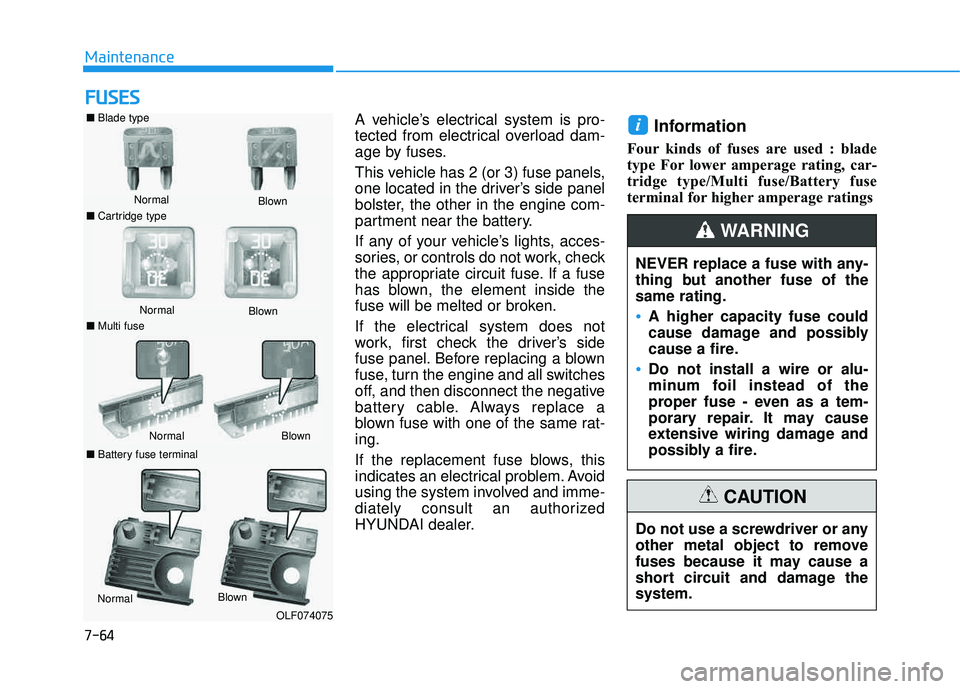
A vehicle’s electrical system is pro-
tected from electrical overload dam-
age by fuses.
This vehicle has 2 (or 3) fuse panels,
one located in the driver’s side panel
bolster, the other in the engine com-
partment near the battery.
If any of your vehicle’s lights, acces-
sories, or controls do not work, check
the appropriate circuit fuse. If a fuse
has blown, the element inside the
fuse will be melted or broken.
If the electrical system does not
work, first check the driver’s side
fuse panel. Before replacing a blown
fuse, turn the engine and all switches
off, and then disconnect the negative
battery cable. Always replace a
blown fuse with one of the same rat-ing.
If the replacement fuse blows, this
indicates an electrical problem. Avoid
using the system involved and imme-
diately consult an authorized
HYUNDAI dealer.Information
Four kinds of fuses are used : blade
type For lower amperage rating, car-
tridge type/Multi fuse/Battery fuse
terminal for higher amperage ratings
i
Do not use a screwdriver or any
other metal object to remove
fuses because it may cause a
short circuit and damage thesystem.
CAUTION
NEVER replace a fuse with any-
thing but another fuse of thesame rating.
A higher capacity fuse could
cause damage and possibly
cause a fire.
Do not install a wire or alu-
minum foil instead of the
proper fuse - even as a tem-
porary repair. It may cause
extensive wiring damage and
possibly a fire.
WARNING
■ Blade type
Normal
■ Cartridge type Blown
Normal
Blown
■ Multi fuse
Normal Blown
■
Battery fuse terminal
Normal Blown
OLF074075
Page 580 of 642
7-67
7
Maintenance
Main fuse
If the main fuse is blown, it must be
removed as follows:
1. Turn off the engine.
2. Disconnect the negative batterycable.
3. Remove the fuse panel cover by pressing the tab and pulling it up.
4. Remove the nuts shown in the pic- ture above.
5. Replace the fuse with a new one of the same rating.
6. Reinstall in the reverse order of removal.
Information
If the main fuse is blown, consult an
authorized HYUNDAI dealer.
i
After checking the fuse box in
the engine compartment
securely close the fuse box
cover inside the engine com-
partment, until it clicks.
If the fuse box is not closed
properly, water may leak in side,
possibly causing a malfunctionwith the electrical system.
CAUTION
OTLA075027
Page 581 of 642
7-68
Maintenance
Multi fuse
If the multi fuse is blown, it must be
removed as follows:
1. Turn off the engine.
2. Disconnect the negative batterycable.
3. Remove the fuse panel cover by pressing the tab and pulling it up.
4. Remove the nuts shown in the pic- ture above.
5. Replace the fuse with a new one of the same rating.
6. Reinstall in the reverse order of removal.
Information
If the multi fuse is blown, consult an
authorized HYUNDAI dealer.
i
OTL075028
Page 588 of 642
![HYUNDAI TUCSON 2016 Owners Manual 7-75
7
Maintenance
Engine compartment main fuse panel
Fuse Name Fuse ratingCircuit Protected
WIPER FRT1 25A Ignition Switch (W/O Smart Key), PDM (IG2) Relay (With Smart Key)
TCU1 15A [G4FJ] TCM HYUNDAI TUCSON 2016 Owners Manual 7-75
7
Maintenance
Engine compartment main fuse panel
Fuse Name Fuse ratingCircuit Protected
WIPER FRT1 25A Ignition Switch (W/O Smart Key), PDM (IG2) Relay (With Smart Key)
TCU1 15A [G4FJ] TCM](/manual-img/35/56201/w960_56201-587.png)
7-75
7
Maintenance
Engine compartment main fuse panel
Fuse Name Fuse ratingCircuit Protected
WIPER FRT1 25A Ignition Switch (W/O Smart Key), PDM (IG2) Relay (With Smart Key)
TCU1 15A [G4FJ] TCM (7DCT)
WIPER FRT2 10A BCM ECU3 20A PCM (G4NC) / ECM (G4FJ)
HORN 15A Horn Relay
BATTERY
MANAGEMENT 10A Battery
Sensor
SENSOR2 10A [G4NC] Oil Control Valve #1/#2, Camshaft Position Sensor #1/#2, Purge Control Solenoid Valve,
Variable Intake Solenoid Valve, Canister Close Valve, Fuel Pump Relay
[G4FJ] Oil Control Valve #1/#2, Purge Control Solenoid Valve, Canister Close Valve, Fuel Pump Relay
SENSOR1 15A [G4NC] PCM, Oxygen Sensor (Up)/(Down) [G4FJ] ECM, Oxygen Sensor (Up)/(Down) ECU2 20A IGNITION COIL #1/#2/#3/#4, Condenser (G4NC)
ECU5 15A PCM (G4NC) / ECM (G4FJ)
ECU4 15A PCM (G4NC) / ECM (G4FJ)
SENSOR3 10A [G4NC] E/R Junction Block (Cooling Fan High Relay)
[G4FJ] Brake Vacuum Switch, RCV Control Solenoid Valve, E/R Junction Block (Cooling Fan High
Relay)
DEICER 15A E/R Junction Block (Front Deicer Relay)
FUEL PUMP1 20A Fuel Pump Relay
MODULE1 7.5A Adaptive Front Lighting Module
B/ALARM HORN 10A E/R Junction Block (B/Alarm Horn Relay) ABS3 10A ESC Module
Page 592 of 642

7-79
7
Maintenance
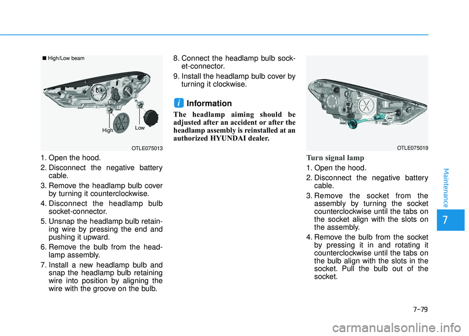
1. Open the hood.
2. Disconnect the negative batterycable.
3. Remove the headlamp bulb cover by turning it counterclockwise.
4. Disconnect the headlamp bulb socket-connector.
5. Unsnap the headlamp bulb retain- ing wire by pressing the end and
pushing it upward.
6. Remove the bulb from the head- lamp assembly.
7. Install a new headlamp bulb and snap the headlamp bulb retaining
wire into position by aligning the
wire with the groove on the bulb. 8. Connect the headlamp bulb sock-
et-connector.
9. Install the headlamp bulb cover by turning it clockwise.
Information
The headlamp aiming should be
adjusted after an accident or after the
headlamp assembly is reinstalled at an
authorized HYUNDAI dealer.
Turn signal lamp
1. Open the hood.
2. Disconnect the negative batterycable.
3. Remove the socket from the assembly by turning the socket
counterclockwise until the tabs on
the socket align with the slots on
the assembly.
4. Remove the bulb from the socket by pressing it in and rotating it
counterclockwise until the tabs on
the bulb align with the slots in the
socket. Pull the bulb out of the
socket.
i
OTLE075013
■High/Low beam
LowHigh
OTLE075019
Page 593 of 642
7-80
Maintenance
5. Install a new bulb by inserting itinto the socket and rotating it until
it locks into place.
6. Install the socket in the assembly by aligning the tabs on the socket
with the slots in the assembly.
7. Push the socket into the assembly and turn the socket clockwise.
Side marker lamp
1. Open the hood.
2. Disconnect the negative batterycable.
3. Remove the socket from the assembly by turning the socket
counterclockwise until the tabs on
the socket align with the slots on
the assembly.
4. Remove the bulb from the socket by pulling out the bulb.
5. Insert a new bulb.
Front fog lamp
1. Remove the front bumper under cover.
2. Reach your hand into the back of the front bumper.
3. Disconnect the power connector from the socket.
4. Remove the bulb-socket from the housing by turning the socket
counter clockwise until the tabs on
the socket align with the slots onthe housing.
OTLA075070OTL075068L
Page 596 of 642

7-83
7
Maintenance
Always handle them carefully, andavoid scratches and abrasions. If
the bulbs are lit, avoid contact with
liquids.
Never touch the glass with bare hands. Residual oil may cause the
bulb to overheat and burst when lit.
A bulb should be operated only when installed in a headlamp.
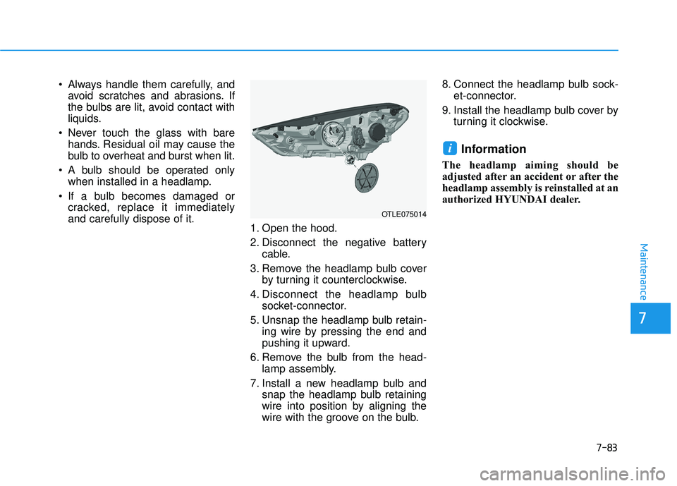
If a bulb becomes damaged or cracked, replace it immediatelyand carefully dispose of it. 1. Open the hood.
2. Disconnect the negative battery
cable.
3. Remove the headlamp bulb cover by turning it counterclockwise.
4. Disconnect the headlamp bulb socket-connector.
5. Unsnap the headlamp bulb retain- ing wire by pressing the end and
pushing it upward.
6. Remove the bulb from the head- lamp assembly.
7. Install a new headlamp bulb and snap the headlamp bulb retaining
wire into position by aligning the
wire with the groove on the bulb. 8. Connect the headlamp bulb sock-
et-connector.
9. Install the headlamp bulb cover by turning it clockwise.
Information
The headlamp aiming should be
adjusted after an accident or after the
headlamp assembly is reinstalled at an
authorized HYUNDAI dealer.
i
OTLE075014