Page 387 of 642
5-3
Driving your vehicle
5
Carbon monoxide (CO) gas is toxic. Breathing CO can cause unconsciousness and death.
Engine exhaust contains carbon monoxide which cannot be seen or smelled.
Do not inhale engine exhaust.
If at any time you smell engine exhaust inside the vehicle, open the windows immediately. Exposure to CO can cause
unconsciousness and death by asphyxiation.
Be sure the exhaust system does not leak.
The exhaust system should be checked whenever the vehicle is raised to change the oil or for any other purpose. If
you hear a change in the sound of the exhaust or if you drive over something that strikes the underneath side of the
vehicle, have the exhaust system checked as soon as possible by an authorized HYUNDAI dealer.
Do not run the engine in an enclosed area.
Letting the engine idle in your garage, even with the garage door open, is a hazardous practice. Run the engine only
long enough to start the engine and to move the vehicle out of the garage.
Avoid idling the engine for prolonged periods with people inside the vehicle.
If it is necessary to idle the engine for a prolonged period with people inside the vehicle , be sure to do so only in an
open area with the air intake set at "Fresh" and fan control set to high so fresh air is drawn into the interior.
Keep the air intakes clear.
To assure proper operation of the ventilation system, keep the ventilation air intakes located in front of the windshield
clear of snow, ice, leaves, or other obstructions.
If you must drive with the liftgate open:
Close all windows.
Open instrument panel air vents.
Set the air intake control at "Fresh", the air flow control at "Floor" or "Face", and the fan control set to high.
WARNING
Page 388 of 642
5-4
Driving your vehicle
Before Entering the Vehicle
• Be sure all windows, outside mir-ror(s), and outside lights are clean
and unobstructed.
Remove frost, snow, or ice.
Visually check the tires for uneven wear and damage.
Check under the vehicle for any sign of leaks.
Be sure there are no obstacles behind you if you intend to back up.
Before Starting
Make sure the hood, the liftgate,and the doors are securely closed
and locked.
Adjust the position of the seat and steering wheel.
Adjust the inside and outside rearview mirrors.
Verify all the lights work.
Fasten your seatbelt. Check that all passengers have fastened their
seatbelts.
Check the gauges and indicators in the instrument panel and the mes-
sages on the instrument display
when the ignition switch is in theON position.
Check that any items you are car- rying are stored properly or fas-
tened down securely.
CALIFORNIA PROPOSITION 65
WARNING
Engine exhaust and a wide vari- ety of automobile components
including components found inthe interior furnishings in a
vehicle, contain or emit harmful
chemicals known to the State of
California to cause cancer and
birth defects and reproductive
harm. In addition, certain fluids
contained in vehicles and cer-
tain products of components
contain or emit chemicals
known to the State of California
to cause cancer and birth
defects or other reproductiveharm.WARNING
BB
EEFFOO RREE DD RRIIVV IINN GG
Page 456 of 642
5-72
Driving your vehicle
LDWS Operation
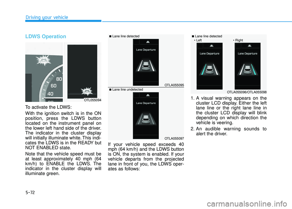
To activate the LDWS:
With the ignition switch is in the ON
position, press the LDWS button
located on the instrument panel on
the lower left hand side of the driver.
The indicator in the cluster display
will initially illuminate white. This indi-
cates the LDWS is in the READY but
NOT ENABLED state.
Note that the vehicle speed must be
at least approximately 40 mph (64
km/h) to ENABLE the LDWS. The
indicator in the cluster display will
illuminate green.If your vehicle speed exceeds 40
mph (64 km/h) and the LDWS button
is ON, the system is enabled. If your
vehicle departs from the projected
lane in front of you, the LDWS oper-
ates as follows:1. A visual warning appears on the
cluster LCD display. Either the left
lane line or the right lane line in
the cluster LCD display will blinkdepending on which direction the
vehicle is veering.
2. An audible warning sounds to alert the driver.
OTLA055095
OTLA055097
■Lane line detected
■Lane line undetected
OTL055094
OTLA055096/OTLA055098
■Lane line detected
Page 478 of 642
5-94
Driving your vehicle
Turn signals
When you tow a trailer, your vehicle
has to have a different turn signal
flasher and extra wiring. The green
arrows on your instrument panel will
flash whenever you signal a turn or
lane change. Properly connected,
the trailer lights will also flash to alert
other drivers you're about to turn,
change lanes, or stop.
When towing a trailer, the green
arrows on your instrument panel will
flash for turns even if the bulbs on the
trailer are burned out. Thus, you may
think drivers behind you are seeing
your signals when, in fact, they are
not. It’s important to check occasion-
ally to be sure the trailer bulbs are still
working. You must also check the
lights every time you disconnect and
then reconnect the wires.
Driving on hills
Reduce speed and shift to a lower
gear before you start down a long or
steep downgrade. If you don't shift
down, you might have to use your
brakes so much that they would get
overheated and may not operate effi-
ciently.
On a long uphill grade, shift down
and reduce your speed to around 45mph (70 km/h) to reduce the possi-
bility of engine and transmission
overheating.
If your trailer weighs more than the
maximum trailer weight without trailer
brakes, you should drive in D (Drive)
when towing a trailer. Operating your
vehicle in D (Drive) when towing a
trailer will minimize heat build-up and
extend the life of your transmission.
Do not connect a trailer lighting
system directly to your vehi-
cle’s lighting system. Use an
approved trailer wiring harness.
Failure to do so could result in
damage to the vehicle electrical
system and/or personal injury.
Consult an authorized HYUNDAI
dealer for assistance.WARNING
Page 515 of 642
7
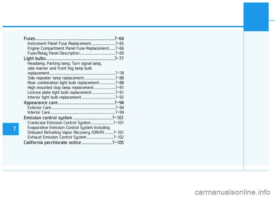
Fuses ......................................................................7-64
Instrument Panel Fuse Replacement..........................7-65
Engine Compartment Panel Fuse Replacement.......7-66
Fuse/Relay Panel Description ......................................7-69
Light bulbs.............................................................7-77
Headlamp, Parking lamp, Turn signal lamp,
side marker and front fog lamp bulb
replacement ......................................................................7-78
Side repeater lamp replacement .................................7-88
Rear combination light bulb replacement .................7-88
High mounted stop lamp replacement .......................7-91
License plate light bulb replacement .........................7-91
Interior light bulb replacement ....................................7-92
Appearance care ..................................................7-94
Exterior Care ....................................................................7-94
Interior Care .....................................................................7-99
Emission control system ...................................7-101
Crankcase Emission Control System ........................7-101
Evaporative Emission Control System Including
Onboard Refueling Vapor Recovery (ORVR) .........7-101
Exhaust Emission Control System ............................7-102
California perchlorate notice ...........................7-105
Page 578 of 642
7-65
7
Maintenance
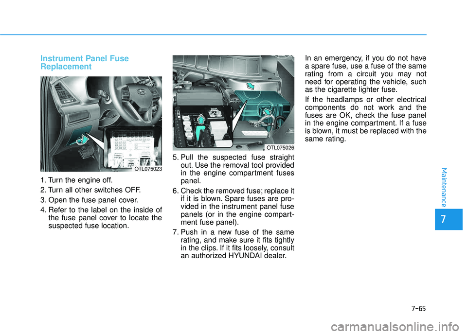
Instrument Panel Fuse Replacement
1. Turn the engine off.
2. Turn all other switches OFF.
3. Open the fuse panel cover.
4. Refer to the label on the inside ofthe fuse panel cover to locate the suspected fuse location. 5. Pull the suspected fuse straight
out. Use the removal tool provided
in the engine compartment fusespanel.
6. Check the removed fuse; replace it if it is blown. Spare fuses are pro-
vided in the instrument panel fuse
panels (or in the engine compart-ment fuse panel).
7. Push in a new fuse of the same rating, and make sure it fits tightly
in the clips. If it fits loosely, consult
an authorized HYUNDAI dealer. In an emergency, if you do not have
a spare fuse, use a fuse of the same
rating from a circuit you may not
need for operating the vehicle, such
as the cigarette lighter fuse.
If the headlamps or other electrical
components do not work and the
fuses are OK, check the fuse panel
in the engine compartment. If a fuse
is blown, it must be replaced with the
same rating.
OTL075026
OTL075023
Page 582 of 642
7-69
7
Maintenance
Fuse/Relay Panel Description
Instrument panel fuse panel
Inside the fuse/relay box cover, you
can find the fuse/relay label describ-
ing fuse/relay name and capacity.
Information
Not all fuse panel descriptions in this
manual may be applicable to your
vehicle; the information is accurate at
the time of printing. When you inspect
the fuse box on your vehicle, refer to
the fuse box label.
i
OTL075067
OTLA075031
Page 583 of 642
7-70
Maintenance
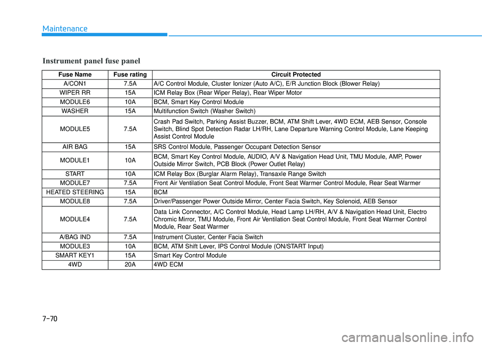
Instrument panel fuse panel
Fuse Name Fuse ratingCircuit Protected
A/CON1 7.5A A/C Control Module, Cluster Ionizer (Auto A/C), E/R Junction Block (Blower Relay)
WIPER RR 15A ICM Relay Box (Rear Wiper Relay), Rear Wiper Motor MODULE6 10A BCM, Smart Key Control Module WASHER 15A Multifunction Switch (Washer Switch)
MODULE5 7.5A Crash Pad Switch, Parking Assist Buzzer, BCM, ATM Shift Lever, 4WD ECM, AEB Sensor, Console
Switch, Blind Spot Detection Radar LH/RH, Lane Departure Warning Control Module, Lane KeepingAssist Control Module
AIR BAG 15A SRS Control Module, Passenger Occupant Detection Sensor
MODULE1 10A BCM, Smart Key Control Module, AUDIO, A/V & Navigation Head Unit, TMU Module, AMP, Power
Outside Mirror Switch, PCB Block (Power Outlet Relay)
START 10A ICM Relay Box (Burglar Alarm Relay), Transaxle Range Switch
MODULE7 7.5A Front Air Ventilation Seat Control Module, Front Seat Warmer Control Module, Rear Seat Warmer
HEATED STEERING 15A BCM MODULE8 7.5A Driver/Passenger Power Outside Mirror, Center Facia Switch, Key Solenoid, AEB Sensor MODULE4 7.5A Data Link Connector, A/C Control Module, Head Lamp LH/RH, A/V & Navigation Head Unit, Electro
Chromic Mirror, TMU Module, Front Air Ventilation Seat Control Module, Front Seat Warmer Control
Module, Rear Seat Warmer
A/BAG IND 7.5A Instrument Cluster, Center Facia Switch MODULE3 10A BCM, ATM Shift Lever, IPS Control Module (ON/START Input)
SMART KEY1 15A Smart Key Control Module 4WD 20A 4WD ECM
