2016 Hyundai Sonata Hybrid cooling
[x] Cancel search: coolingPage 545 of 708

6-7
What to do in an emergency
6
If your engine coolant temperature
gauge indicates overheating, you
experience a loss of power, or hear
loud pinging or knocking, the engine
may be overheating. If this happens,
you should:
1. Turn ON the hazard warning flash-er, pull off the road and stop as
soon as it is safe to do so.
2. Place the shift lever in P (Park) and set the parking brake.
3. Make sure that there is no hotsteam gushing out of the engine
compartment. When it is safe to
do so, open the engine compart-
ment, and check the water-pump
connector. When the water-pump
connector is disconnected, stop
the engine, re-connect the water-
pump connector, and then re-start
the engine.
4. Set the temperature and the air flow to the maximum, and turn ON
the air conditioner. 5. When the Service warning light
( ) illuminates on the instru-
ment cluster, immediately stop the
engine, and contact an authorized
HYUNDAI dealer. When the
engine warning light ( ) illumi-
nates, or when the coolant or hot
steams gush out of the engine
compartment, leave the engine
compartment opened, while run-
ning the engine. This is to ventilate
the engine compartment and to
cool down the engine.
6. Check the coolant temperature gauge on the instrument cluster to
make sure the coolant temperature
is sufficiently cooled down. Check
the coolant level. When it is insuffi-
cient, check its connection with the
radiator, the heater hose, and the
water pump for any leakage. When
there is no leakage, add the
coolant. However, if the problems
persists, such as the illumination of
the warning lights, leakages, or the
cooling-fan malfunction, which may
overheat the engine, immediately
stop the engine, and have your
vehicle checked by an authorized
HYUNDAI dealer.
I
IF
F
T
T H
H E
E
E
E N
N G
GI
IN
N E
E
O
O V
VE
ER
R H
H E
EA
A T
TS
S
OLFH064029L
Page 546 of 708

6-8
What to do in an emergency7. If you cannot find the cause of theoverheating, wait until the engine
temperature has returned to nor-
mal. Then, if coolant has been
lost, carefully add coolant to the
reservoir to bring the fluid level in
the reservoir up to the halfway
mark.
8. Proceed with caution, keeping alert for further signs of overheat-
ing. If overheating happens again,
call an authorized HYUNDAI deal-
er for assistance.
Serious loss of coolant indi-
cates a leak in the cooling sys-
tem and should be checked as
soon as possible by an author-
ized HYUNDAI dealer.
CAUTION
The electric motor for
the cooling fan may
continue to operate
or start up when the
engine is not running
and can cause serious injury.
Keep hands, clothing and tools
away from the rotating fan
blades of the cooling fan.
WARNING
Never remove the
radiator cap and/or
inverter coolant cap
or the drain plug
while the engine and
radiator are hot. Hot coolant
and steam may blow out under
pressure, causing serious
injury.
Turn the engine off and wait
until the engine cools down.
Use extreme care when remov-
ing the radiator cap and/or
inverter coolant cap. Wrap a
thick towel around it, and turn it
counterclockwise slowly to the
first stop. Step back while the
pressure is released from the
cooling system. When you are
sure all the pressure has been
released, press down on the
cap, using a thick towel, and
continue turning counterclock-
wise to remove it.
WARNING
Page 589 of 708

7-25
7
Maintenance
Cooling system
Check cooling system components,
such as radiator, coolant reservoir,
hoses and connections for leakage
and damage. Replace any damaged
parts.
Engine coolant/Inverter
coolant
The coolant should be changed at
the intervals specified in the mainte-
nance schedule.
Automatic transaxle fluid
Automatic transaxle fluid should not
be checked under normal usage con-
ditions. But in severe conditions, the
fluid should be changed at an author-
ized HYUNDAI dealer in accordance
to the scheduled maintenance at the
beginning of this chapter.
Automatic transaxle fluid color is
basically red.
As the vehicle is driven, the auto-
matic transaxle fluid will begin to
look darker. This is a normal con-
dition and you should not judge
the need to replace the fluid based
upon the changed color.
Brake hoses and lines
Visually check for proper installation,
chafing, cracks, deterioration and
any leakage. Replace any deteriorat-
ed or damaged parts immediately.
Brake fluid
Check brake fluid level in the brake
fluid reservoir. The level should be
between the MIN and the MAX
marks on the side of the reservoir.
Use only hydraulic brake fluid con-
forming to DOT 3 or DOT 4 specifi-
cation.
Parking brake
Inspect the parking brake system
including the parking brake pedal
and cables.
NOTICE
The use of a non-specified fluid
could result in transaxle mal-
function and failure. Use only
the specified automatic
transaxle fluid (refer to
“Recommended Lubricants and
Capacities” in chapter 8).
CAUTION
Page 593 of 708

7-29
7
Maintenance
E
EN
N G
GI
IN
N E
E
C
C O
O O
OL
LA
A N
N T
T/
/I
IN
N V
VE
ER
R T
TE
ER
R
C
C O
O O
OL
LA
A N
N T
T
The high-pressure cooling system
has a reservoir filled with year-round
antifreeze coolant. The reservoir is
filled at the factory.
Check the antifreeze protection and
coolant level at least once a year, at
the beginning of the winter season
and before traveling to a colder cli-
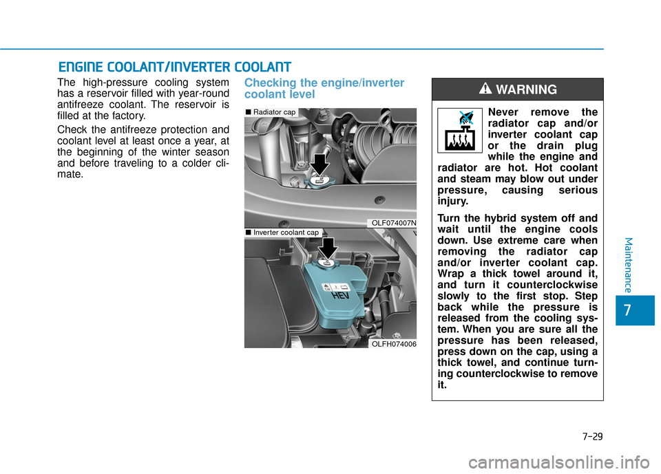
mate.Checking the engine/inverter
coolant level
OLF074007N
OLFH074006
■ Radiator cap
■Inverter coolant cap
Never remove the
radiator cap and/or
inverter coolant cap
or the drain plug
while the engine and
radiator are hot. Hot coolant
and steam may blow out under
pressure, causing serious
injury.
Turn the hybrid system off and
wait until the engine cools
down. Use extreme care when
removing the radiator cap
and/or inverter coolant cap.
Wrap a thick towel around it,
and turn it counterclockwise
slowly to the first stop. Step
back while the pressure is
released from the cooling sys-
tem. When you are sure all the
pressure has been released,
press down on the cap, using a
thick towel, and continue turn-
ing counterclockwise to remove
it.
WARNING
Page 594 of 708

7-30
Maintenance
Information
The engine coolant and/or inverter
coolant level is influenced by the
hybrid system temperature. Before
checking or refilling the engine
coolant and/or inverter coolant, turn
the hybrid vehicle off. The electric motor for the cooling fan
is controlled by engine coolant tem-
perature, refrigerant pressure and
vehicle speed. As the engine coolant
temperature decreases, the electric
motor will automatically shut off. This
is a normal condition. If your vehicle
is equipped with GDI, the electric
motor for the cooling fan may begin
to operate at any time and continue
to operate until you disconnect the
negative battery cable.
Engine coolant
Check the condition and connections
of all cooling system hoses and
heater hoses. Replace any swollen
or deteriorated hoses.
The coolant level should be filled
between the F and the L marks on
the side of the coolant reservoir
when the engine is cool.
If the coolant level is low, add enough
distilled (deionized) water to bring
the level to the F mark, but do not
overfill. If frequent additions are
required, See an authorized
HYUNDAI dealer for a cooling sys-
tem inspection.
i
The electric motor for
the cooling fan may
continue to operate
or start up when the
engine is not running
and can cause serious injury.
Keep hands, clothing and tools
away from the rotating fan
blades of the cooling fan.
WARNING
OLF074006N
Page 595 of 708

7-31
7
Maintenance
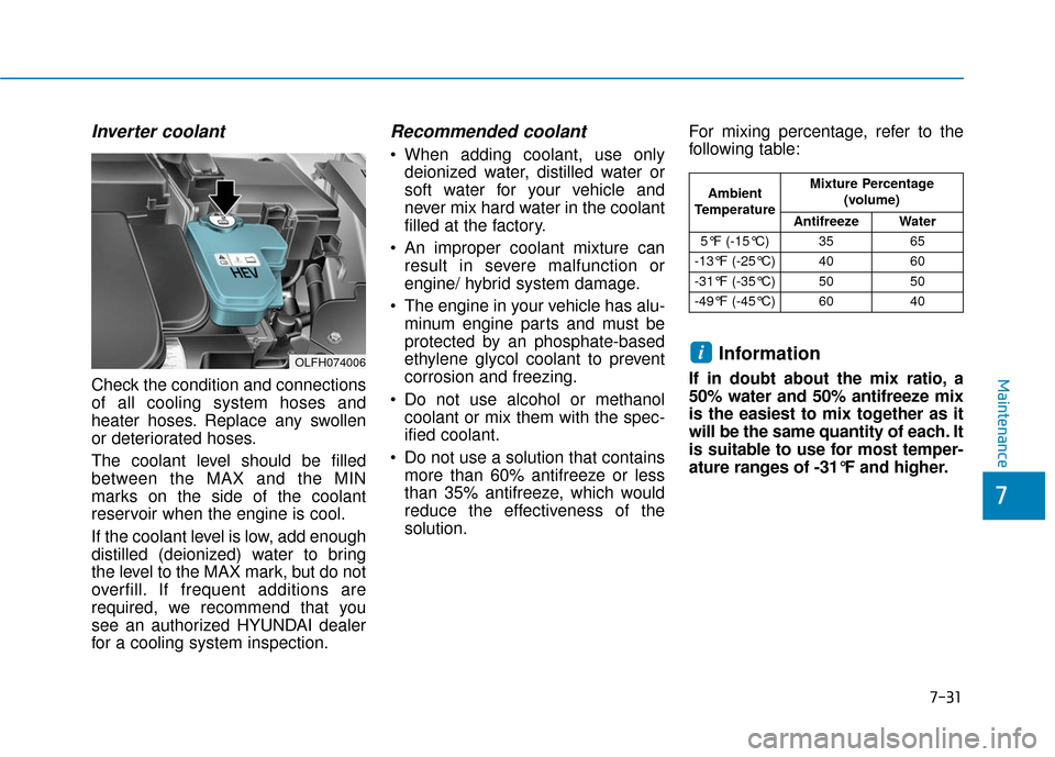
Inverter coolant
Check the condition and connections
of all cooling system hoses and
heater hoses. Replace any swollen
or deteriorated hoses.
The coolant level should be filled
between the MAX and the MIN
marks on the side of the coolant
reservoir when the engine is cool.
If the coolant level is low, add enough
distilled (deionized) water to bring
the level to the MAX mark, but do not
overfill. If frequent additions are
required, we recommend that you
see an authorized HYUNDAI dealer
for a cooling system inspection.
Recommended coolant
When adding coolant, use onlydeionized water, distilled water or
soft water for your vehicle and
never mix hard water in the coolant
filled at the factory.
An improper coolant mixture can result in severe malfunction or
engine/ hybrid system damage.
The engine in your vehicle has alu- minum engine parts and must be
protected by an phosphate-based
ethylene glycol coolant to prevent
corrosion and freezing.
Do not use alcohol or methanol coolant or mix them with the spec-
ified coolant.
Do not use a solution that contains more than 60% antifreeze or less
than 35% antifreeze, which would
reduce the effectiveness of the
solution. For mixing percentage, refer to the
following table:
Information
If in doubt about the mix ratio, a
50% water and 50% antifreeze mix
is the easiest to mix together as it
will be the same quantity of each. It
is suitable to use for most temper-
ature ranges of -31°F and higher.
i
Ambient
Temperature Mixture Percentage
(volume)
Antifreeze Water
5°F (-15°C) 35 65
-13°F (-25°C) 40 60
-31°F (-35°C) 50 50
-49°F (-45°C) 60 40
OLFH074006
Page 633 of 708

7-69
7
Maintenance
Engine compartment main fuse panel
Fuse NameFuse rating Protected Component
MULTIFUSE
(TYPE A)
IG230AIGPM (Fuse - F8/F25/F31/F38/F42)
BLOWER40ARLY. 9 (Blower Relay)
2AHB40AIntegrated Brake Actuation Unit
1AHB40AIntegrated Brake Actuation Unit
REAR HEATED50ARLY. 12 (Rear Heated Relay)
3B+50AIGPM (IPS2 (4CH), IPS3 (4CH), Fuse - F28/F29)
5B+50APCM Block (Fuse - F4/F5/F6/F13/F14/F18/F22, Engine Control Relay)
EEWP60AElectric Water Pump
1MDPS80AMDPS Unit
MULTI FUSE
(TYPE B)
IG140AIGPM (Fuse - F14/F19/F20/F26/F27/F33/F34/F40/F41/F47/F46)
POWER OUTLET40ARLY. 10 (Power Outlet Relay)
2B+50AIGPM (IPS1 (4CH), IPS4 (4CH), IPS5 (4CH), Fuse - F36/F42)
1B+60AIGPM (Fuse - F1/F2/F10/F13/F17/F18/F23/F24/F30, Power Window Relay)
COOLING FAN60ARLY.2 (Cooling Fan Relay)
FUSE
DEICER20ARLY. 6 (Deicer Relay)
1OPCU20AElectric Oil Pump Unit
1HEV ECU10AHPCU
Page 634 of 708

7-70
Maintenance
Fuse Name Fuse rating Protected Component
FUSE
H/LAMP HI20ARLY. 7 (Head Lamp High Relay)
4B+40AIGPM (Leak Current Autocut Device Fuse - F15/F16/F21/F22, Fuse - F5/F6/F7/F11/F12)
2EPB30AElectric Parking Brake Module
1EPB30AElectric Parking Brake Module
HEATED MIRROR10AA/C Control Module, Drover/Passenger Power Outside Mirror
3ECU10APCM
2HEV ECU10AHPCU
1POWER OUTLET20ACigarette Lighter
FUEL PUMP20AFuel Pump Relay
HORN20AHorn Relay, ICM Relay Box (Burglar Alarm Horn Relay)
WIPER30AFront Wiper (Low) Relay, Front Wiper (High) Relay
2TCU15ATransaxle Range Switch, Electric Water Pump
3AHB10AIntegrated Brake Actuation Unit
2POWER OUTLET20ARear Power Outlet
B/UP LAMP10ATransaxle Range Switch, PCM, Audio, Electro Chromic Mirror, Back-Up Lamp LH/RH,
Rear Curtain Unit
1SENSOR15AOxygen Sensor (Up/Down)
2SENSOR10AE/R Junction Block (RLY. 2 - Cooling Fan Relay), Mass Air Flow Sensor, Oil Control Valve
#1/#2, Purge Control Solenoid Valve, Canister Close Valve, Camshaft Position Sensor
#1/#2, Fuel Pump Relay
2ECU10APCM