2016 Hyundai Santa Fe Sport air condition
[x] Cancel search: air conditionPage 82 of 763
361
Safety features of your vehicle
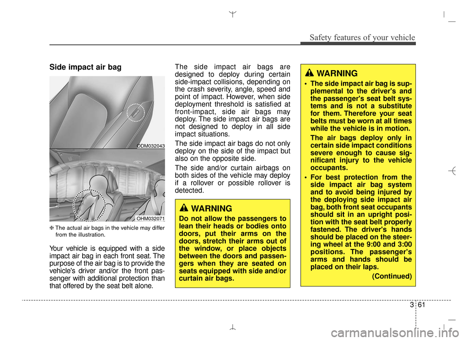
Side impact air bag
❈The actual air bags in the vehicle may differ
from the illustration.
Your vehicle is equipped with a side
impact air bag in each front seat. The
purpose of the air bag is to provide the
vehicle's driver and/or the front pas-
senger with additional protection than
that offered by the seat belt alone. The side impact air bags are
designed to deploy during certain
side-impact collisions, depending on
the crash severity, angle, speed and
point of impact. However, when side
deployment threshold is satisfied at
front-impact, side air bags may
deploy. The side impact air bags are
not designed to deploy in all side
impact situations.
The side impact air bags do not only
deploy on the side of the impact but
also on the opposite side.
The side and/or curtain airbags on
both sides of the vehicle may deploy
if a rollover or possible rollover is
detected.
WARNING
Do not allow the passengers to
lean their heads or bodies onto
doors, put their arms on the
doors, stretch their arms out of
the window, or place objects
between the doors and passen-
gers when they are seated on
seats equipped with side and/or
curtain air bags.
WARNING
The side impact air bag is sup-
plemental to the driver's and
the passenger's seat belt sys-
tems and is not a substitute
for them. Therefore your seat
belts must be worn at all times
while the vehicle is in motion.
The air bags deploy only in
certain side impact conditions
severe enough to cause sig-
nificant injury to the vehicle
occupants.
For best protection from the side impact air bag system
and to avoid being injured by
the deploying side impact air
bag, both front seat occupants
should sit in an upright posi-
tion with the seat belt properly
fastened. The driver's hands
should be placed on the steer-
ing wheel at the 9:00 and 3:00
positions. The passenger's
arms and hands should be
placed on their laps.
(Continued)
ODM032043
OHM032071
AN HMA 3.QXP 3/5/2015 3:09 PM Page 61
Page 85 of 763
Safety features of your vehicle
64
3
Why didn’t my air bag go off in a
collision? (Inflation and non-infla-
tion conditions of the air bag)
There are many types of accidents
in which the air bag would not be
expected to provide additional
protection.
These include rear impacts, sec-
ond or third collisions in multiple
impact accidents, as well as low
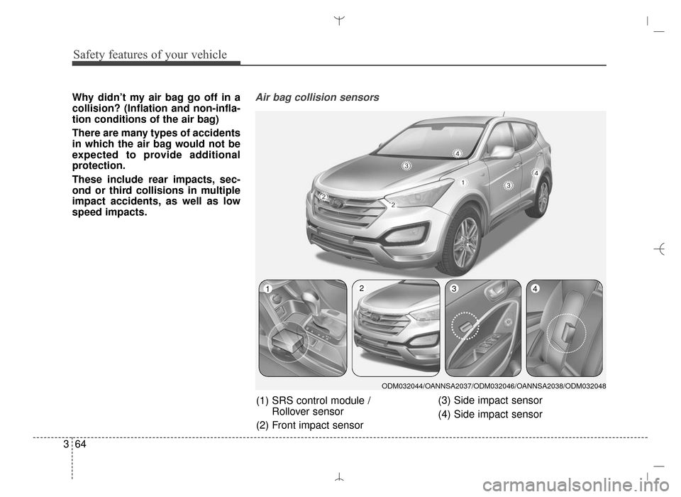
speed impacts.Air bag collision sensors
(1) SRS control module /
Rollover sensor
(2) Front impact sensor (3) Side impact sensor
(4) Side impact sensor
ODM032044/OANNSA2037/ODM032046/OANNSA2038/ODM032048
1234
AN HMA 3.QXP 3/5/2015 3:10 PM Page 64
Page 86 of 763
365
Safety features of your vehicle
Problems may arise if the sensorinstallation angles are changed
due to the deformation of the front
bumper, body or C pillars or front
door where side collision sensors
are installed. Have the vehicle
checked and repaired by an
authorized HYUNDAI dealer.
Your vehicle has been designed to absorb impact and deploy the air
bag(s) in certain collisions.
Installing bumper guards or side
steppers or replacing a bumper
with non-genuine parts may
adversely affect your vehicle’s col-
lision and air bag deployment per-
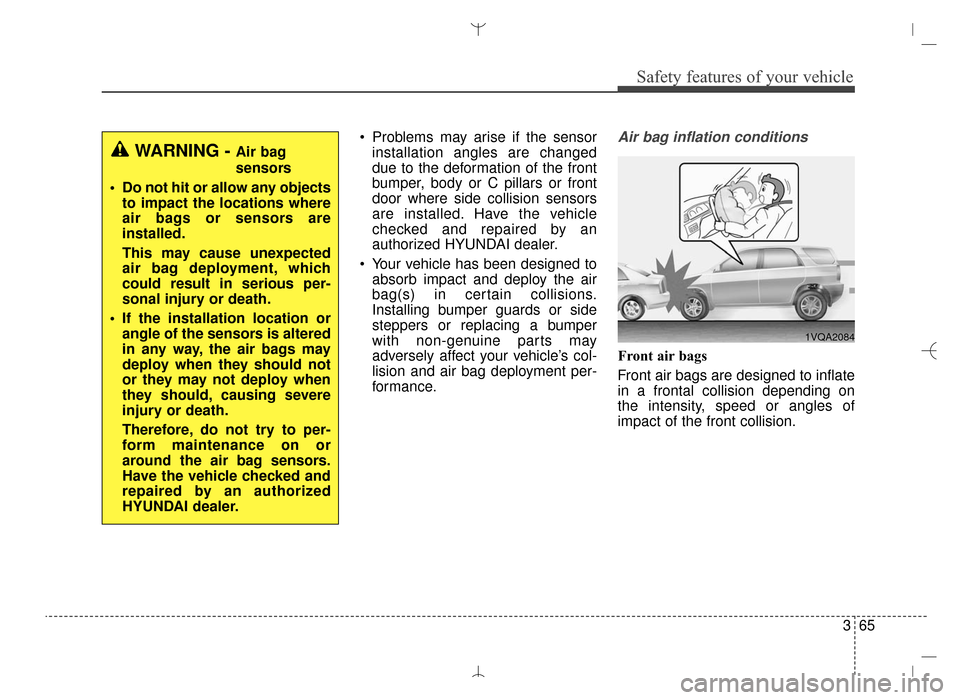
formance.Air bag inflation conditions
Front air bags
Front air bags are designed to inflate
in a frontal collision depending on
the intensity, speed or angles of
impact of the front collision.
WARNING - Air bag
sensors
Do not hit or allow any objects to impact the locations where
air bags or sensors are
installed.
This may cause unexpected
air bag deployment, which
could result in serious per-
sonal injury or death.
If the installation location or angle of the sensors is altered
in any way, the air bags may
deploy when they should not
or they may not deploy when
they should, causing severe
injury or death.
Therefore, do not try to per-
form maintenance on or
around the air bag sensors.
Have the vehicle checked and
repaired by an authorized
HYUNDAI dealer.
1VQA2084
AN HMA 3.QXP 3/5/2015 3:10 PM Page 65
Page 88 of 763
367
Safety features of your vehicle
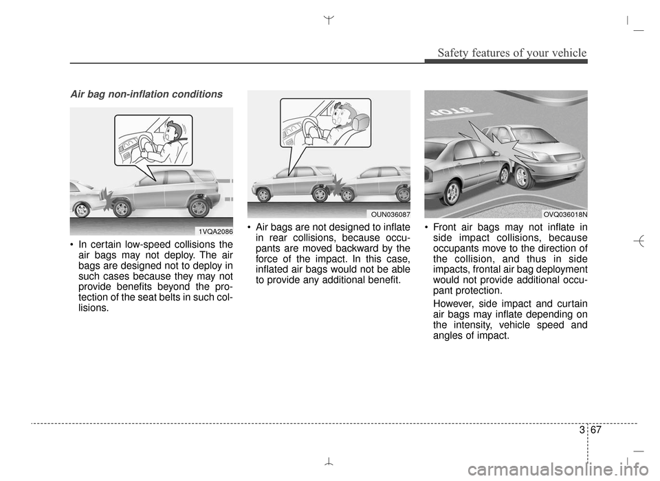
Air bag non-inflation conditions
In certain low-speed collisions theair bags may not deploy. The air
bags are designed not to deploy in
such cases because they may not
provide benefits beyond the pro-
tection of the seat belts in such col-
lisions. Air bags are not designed to inflate
in rear collisions, because occu-
pants are moved backward by the
force of the impact. In this case,
inflated air bags would not be able
to provide any additional benefit. Front air bags may not inflate in
side impact collisions, because
occupants move to the direction of
the collision, and thus in side
impacts, frontal air bag deployment
would not provide additional occu-
pant protection.
However, side impact and curtain
air bags may inflate depending on
the intensity, vehicle speed and
angles of impact.
OVQ036018NOUN036087
1VQA2086
AN HMA 3.QXP 3/5/2015 3:10 PM Page 67
Page 95 of 763
• Puddle lamp and pocket lamp . . . . . . . . . . . . . . . . . 4-133
Defroster . . . . . . . . . . . . . . . . . . . . . . . . . . . . . . . . 4-134
• Rear window defroster . . . . . . . . . . . . . . . . . . . . . . . 4-134
• Front wiper deicer . . . . . . . . . . . . . . . . . . . . . . . . . . . 4-134
Manual climate control system . . . . . . . . . . . . . . 4-135
• Heating and air conditioning . . . . . . . . . . . . . . . . . . 4-136
• System operation . . . . . . . . . . . . . . . . . . . . . . . . . . . . 4-141
• Climate control air filter. . . . . . . . . . . . . . . . . . . . . . 4-143
• Refrigerant and compressor lubricant . . . . . . . . . . 4-144
• Air Conditioning refrigerant label. . . . . . . . . . . . . . 4-144
Automatic climate control system . . . . . . . . . . . 4-145
• Automatic heating and air conditioning . . . . . . . . . 4-146
• Manual heating and air conditioning . . . . . . . . . . . 4-147
Windshield defrosting and defogging . . . . . . . . . 4-153
• Manual climate control system . . . . . . . . . . . . . . . . 4-153
• Automatic climate control system . . . . . . . . . . . . . . 4-154
Storage compartment . . . . . . . . . . . . . . . . . . . . . . 4-156
• Center console storage . . . . . . . . . . . . . . . . . . . . . . . 4-156
• Glove box . . . . . . . . . . . . . . . . . . . . . . . . . . . . . . . . . . 4-15\
6
• Multi box . . . . . . . . . . . . . . . . . . . . . . . . . . . . . . . . . . 4-15\
7
• Sunglass holder . . . . . . . . . . . . . . . . . . . . . . . . . . . . . 4-157
• Luggage tray . . . . . . . . . . . . . . . . . . . . . . . . . . . . . . . 4-158
Interior features . . . . . . . . . . . . . . . . . . . . . . . . . . 4-159
• Cup holder . . . . . . . . . . . . . . . . . . . . . . . . . . . . . . . . . 4-159
• Sunvisor . . . . . . . . . . . . . . . . . . . . . . . . . . . . . . . . . . . 4-\
160• Power outlet . . . . . . . . . . . . . . . . . . . . . . . . . . . . . . . . 4-160
• Clothes hanger . . . . . . . . . . . . . . . . . . . . . . . . . . . . . . 4-162
• Floor mat anchor(s). . . . . . . . . . . . . . . . . . . . . . . . . . 4-162
• Aux, USB and iPod
®port . . . . . . . . . . . . . . . . . . . . . 4-163
• Luggage net (holder) . . . . . . . . . . . . . . . . . . . . . . . . . 4-163
• Cargo security screen . . . . . . . . . . . . . . . . . . . . . . . . 4-164
• Side curtain . . . . . . . . . . . . . . . . . . . . . . . . . . . . . . . . 4-166
Exterior features . . . . . . . . . . . . . . . . . . . . . . . . . . 4-167
• Roof rack . . . . . . . . . . . . . . . . . . . . . . . . . . . . . . . . . . 4-16\
7
Audio system . . . . . . . . . . . . . . . . . . . . . . . . . . . . . 4-169
• Antenna . . . . . . . . . . . . . . . . . . . . . . . . . . . . . . . . . . . 4-\
169
• Audio remote control . . . . . . . . . . . . . . . . . . . . . . . . 4-1704
AN HMA 4A.QXP 3/5/2015 3:17 PM Page 3
Page 123 of 763
431
Features of your vehicle
✽
✽NOTICE
• The power liftgate (power tailgate)
can be operated when the engine is
not running. However the power
liftgate (power tailgate) operation
consumes large amounts of vehicle
electric power. To prevent the bat-
tery from being discharged, do not
operate it excessively e.g.: more
than approximately 10 times
repeatedly.
• To prevent the battery from being discharged, do not leave the power
liftgate (power tailgate) in the
open position for a long lime.
• Do not modify or repair any part of the power liftgate (power tail-
gate) by yourself. This must be
done by an authorized HYUNDAI
dealer.
• When jacking up the vehicle to change a tire or repair the vehicle,
do not operate the power liftgate
(power tailgate). This could cause
the power liftgate (power tailgate)
to operate improperly.
• In cold and wet climates, the power liftgate (power tailgate) may
not work properly due to freezing
conditions.
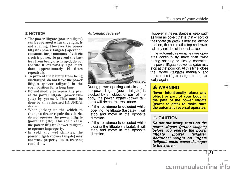
Automatic reversal
During power opening and closing if
the power liftgate (power tailgate) is
blocked by an object or part of the
body, the power liftgate (power tail-
gate) will detect the resistance.
If the resistance is detected while
opening the liftgate (tailgate), it will
stop and move in the opposite
direction.
If the resistance is detected while closing the liftgate (tailgate), it will
stop and move in the opposite
direction. However, if the resistance is weak such
as from an object that is thin or soft, or
the liftgate (tailgate) is near the latched
position, the automatic stop and rever-
sal may not detect the resistance.
If the automatic reversal feature oper-
ates continuously more than twice
during opening or closing operation,
the power liftgate (power tailgate) may
stop at that position. At this time, close
the liftgate (tailgate) manually and
operate the liftgate (tailgate) automat-
ically again.
ODM044506
WARNING
Never intentionally place any
object or part of your body in
the path of the power liftgate
(power tailgate) to make sure
the automatic reversal operates.
CAUTION
Do not put heavy stuffs on the
power liftgate (power tailgate)before you operate the powerliftgate (power tailgate).Additional weight on liftgate(tailgate) could cause damagesto the system.
AN HMA 4A.QXP 3/5/2015 3:18 PM Page 31
Page 155 of 763
463
Features of your vehicle
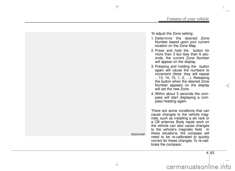
To adjust the Zone setting:
1. Determine the desired ZoneNumber based upon your current
location on the Zone Map.
2. Press and hold the button for more than 3 but less than 6 sec-
onds, the current Zone Number
will appear on the display.
3. Pressing and holding the button again will cause the numbers to
increment (Note: they will repeat
…13, 14, 15, 1, 2, …). Releasing
the button when the desired Zone
Number appears on the display
will set the new Zone.
4. Within about 5 seconds the com- pass will start displaying a com-
pass heading again.
There are some conditions that can
cause changes to the vehicle mag-
nets, such as installing a ski rack or
a CB antenna. Body repair work on
the vehicle can also cause changes
to the vehicle's magnetic field. In
these situations, the compass will
need to be re-calibrated to quickly
correct for these changes. To re-cali-
brate the compass:
B520C05NF
AN HMA 4A.QXP 3/5/2015 3:18 PM Page 63
Page 163 of 763
471
Features of your vehicle
To adjust the Zone setting:
1. Determine the desired ZoneNumber based upon your current
location on the Zone Map.
2. Press and hold the button for 6 seconds, the current Zone
Number will appear on the display.
3. Pressing and holding the button again will cause the numbers to
increment (Note: they will repeat
…13, 14, 15, 1, 2, …). Releasing
the button when the desired Zone
Number appears on the display
will set the new Zone.
4. Within about 5 seconds the com- pass will start displaying a com-
pass heading again.
There are some conditions that can
cause changes to the vehicle mag-
nets, such as installing a ski rack or
a CB antenna. Body repair work on
the vehicle can also cause changes
to the vehicle's magnetic field. In
these situations, the compass will
need to be re-calibrated to quickly
correct for these changes. To re-cali-
brate the compass: 1. Press and hold the button for
more than 9 seconds. When the
compass memory is cleared a "C"
will appear in the display.
2. To calibrate the compass, drive the vehicle in 2 complete circles at
less than 5 mph (8 km/h). Integrated HomeLink®Wireless
Control System
The HomeLink
®Wireless Control
System provides a convenient way to
replace up to three hand-held radio-
frequency (RF) transmitters with a
single built-in device. This innovative
feature will learn the radio frequency
codes of most current transmitters to
operate devices such as gate opera-
tors, garage door openers, entry
door locks, security systems, even
home lighting. Both standard and
rolling code-equipped transmitters
can be programmed by following the
outlined procedures. Additional
HomeLink
®information can be found
at: www.homelink.com or by calling
1-800-355-3515.
AN HMA 4A.QXP 3/5/2015 3:18 PM Page 71