2016 FORD SUPER DUTY parking brake
[x] Cancel search: parking brakePage 170 of 510
GENERAL INFORMATION
Note:
Occasional brake noise is normal. If
a metal-to-metal, continuous grinding or
continuous squeal sound is present, the
brake linings may be worn-out. Have the
system checked by an authorized dealer. If
your vehicle has continuous vibration or
shudder in the steering wheel while braking,
have it checked by an authorized dealer.
Note: Brake dust may accumulate on the
wheels, even under normal driving
conditions. Some dust is inevitable as the
brakes wear and does not contribute to
brake noise. See Cleaning the Alloy
Wheels (page 261). See
Warning Lamps and
Indicators (page 83).
Wet brakes result in reduced braking
efficiency. Gently press the brake pedal a
few times when driving from a car wash or
standing water to dry the brakes.
Brake Over Accelerator
In the event the accelerator pedal
becomes stuck or entrapped, apply steady
and firm pressure to the brake pedal to
slow the vehicle and reduce engine power.
If you experience this condition, apply the
brakes and bring your vehicle to a safe
stop. Move the transmission to park (P),
switch the engine off and apply the parking
brake. Inspect the accelerator pedal for
any interference. If none are found and the
condition persists, have your vehicle towed
to the nearest authorized dealer.
Brake Assist
Brake assist detects when you brake
rapidly by measuring the rate at which you
press the brake pedal. It provides
maximum braking efficiency as long as you
press the pedal, and can reduce stopping
distances in critical situations. Anti-lock Brake System
This system helps you maintain steering
control during emergency stops by keeping
the brakes from locking. This lamp momentarily
illuminates when you turn the
ignition on. If the light does not
illuminate during start up, remains on or
flashes, the system may be disabled. Have
the system checked by an authorized
dealer. If the anti-lock brake system is
disabled, normal braking is still effective. If the brake warning lamp
illuminates when you release the
parking brake, have the system
checked by an authorized dealer.
HINTS ON DRIVING WITH
ANTI-LOCK BRAKES
Note: When the system is operating, the
brake pedal may pulse and may travel
further. Maintain pressure on the brake
pedal. You may also hear a noise from the
system. This is normal.
The anti-lock braking system will not
eliminate the risks when:
• You drive too closely to the vehicle in
front of you.
• Your vehicle is hydroplaning.
• You take corners too fast.
• The road surface is poor.
167
Super Duty (TFA) Canada/United States of America, enUSA, Second Printing BrakesE144522 E144522
Page 171 of 510
PARKING BRAKE
WARNING
Always set the parking brake fully
and make sure the transmission is
placed in park (P). Failure to set the
parking brake and engage park could result
in vehicle roll-away, property damage or
bodily injury. Turn the ignition to the lock
position and remove the key whenever you
leave your vehicle. Apply the parking brake whenever your
vehicle is parked. Press the pedal
downward to set the parking brake. The
brake warning lamp in the instrument
cluster will illuminate and remains
illuminated until the parking brake is
released.
To release, pull the brake release lever
located at the lower left side of the
instrument panel.
If you are parking your vehicle on a grade
or with a trailer, press and hold the brake
pedal down, then set the parking brake.
There may be a little vehicle movement as
the parking brake sets to hold the vehicle's
weight. This is normal and should be no
reason for concern. If needed, press and
hold the service brake pedal down, then
try reapplying the parking brake. Chock the
wheels if required. If the parking brake
cannot hold the weight of the vehicle, the
parking brake may need to be serviced or
the vehicle may be overloaded.
HILL START ASSIST
WARNINGS
The system does not replace the
parking brake. When you leave your
vehicle, always apply the parking
brake. Failure to leave your vehicle securely
parked may lead to a crash or injury. See
Parking Brake (page 168). WARNINGS
You must remain in your vehicle
when the system turns on. At all
times, you are responsible for
controlling your vehicle, supervising the
system and intervening, if required. Failure
to take care may result in the loss of
control of your vehicle, serious personal
injury or death. The system will turn off if a
malfunction is apparent or if you rev
the engine excessively. Failure to
take care may result in the loss of control
of your vehicle, serious personal injury or
death. The system makes it easier to pull away
when your vehicle is on a slope without the
need to use the parking brake.
When the system is active, your vehicle
remains stationary on the slope for two to
three seconds after you release the brake
pedal. This allows time to move your foot
from the brake to the accelerator pedal.
The system releases the brakes
automatically once the engine has
developed sufficient torque to prevent your
vehicle from rolling down the slope. This
is an advantage when pulling away on a
slope, for example from a car park ramp,
traffic lights or when reversing uphill into
a parking space.
Note:
The system only functions when you
bring your vehicle to a complete standstill
in an uphill gear (for example, drive (D)
when facing uphill or reverse (R) when
facing downhill).
Note: There is no warning light to indicate
the system is either on or off.
Using Hill Start Assist
1. Press the brake pedal to bring your vehicle to a complete standstill. Keep
the brake pedal pressed.
168
Super Duty (TFA) Canada/United States of America, enUSA, Second Printing Brakes
Page 178 of 510
PRINCIPLE OF OPERATION
WARNINGS
Hill descent control cannot control
descent in all surface conditions and
circumstances, such as ice or
extremely steep grades. Hill descent
control is a driver assist system and cannot
substitute for good judgment by the driver.
Failure to do so may result in loss of vehicle
control, crash or serious injury. Hill descent control does not provide
hill hold at zero miles per hour (0
kilometers per hour). When stopped,
the parking brake must be applied or the
vehicle must be placed in P (Park) or it
may roll away. Hill descent control allows the driver to set
and maintain vehicle speed while
descending steep grades in various surface
conditions.
Hill descent control can maintain vehicle
speeds on downhill grades between 2 mph
(3 km/h) and 12 mph (20 km/h). Above 20
mph (32 km/h), the system remains
armed, but descent speed cannot be set
or maintained.
Hill descent control requires a cooling
down interval after a period of sustained
use. The amount of time that the feature
can remain active before cooling varies
with conditions. The system will provide a
warning in the message center and a chime
will sound when the system is about to
disengage for cooling. At this time,
manually apply the brakes as needed to
maintain descent speed. USING HILL DESCENT
CONTROL Press and release the hill
descent button located on the
instrument panel. A light in the
cluster will illuminate and a chime will
sound when this feature is activated.
To increase descent speed, press the
accelerator pedal until the desired speed
is reached. To decrease descent speed,
press the brake pedal until the desired
speed is reached.
Whether accelerating or decelerating, once
the desired descent speed is reached,
remove your feet from the pedals and the
chosen vehicle speed will be maintained.
Note: Noise from the ABS pump motor may
be observed during hill descent control
operation. This is a normal characteristic of
the ABS and should be no reason for
concern.
Hill descent modes
• At speeds below 20 mph (32 km/h):
When the Hill Descent Control switch
is pressed and Hill Descent Control is
active, the Hill Descent Control telltale
will flash.
• At speeds below 20 mph (32 km/h):
When the Hill Descent Control switch
is pressed and conditions are not
correct for hill descent activation, the
Hill Descent Control system will be
enabled, the Hill Descent Control
telltale will be solid and a message will
display in the information display.
• At speeds above 20 mph (32 km/h):
When the Hill Descent Control switch
is pressed, the Hill Descent Control
system will be enabled, the telltale in
the cluster will not be illuminated and
a message will be displayed in the
information display.
175
Super Duty (TFA) Canada/United States of America, enUSA, Second Printing Terrain Response
(If Equipped)E163957
Page 200 of 510
When hooking-up a trailer using a
weight-distributing hitch, always use the
following procedure:
1. Park the loaded vehicle, without the
trailer, on a level surface.
2. Measure the height to the top of your vehicle's front wheel opening on the
fender. This is H1.
3. Attach the loaded trailer to your vehicle
without the weight-distributing bars
connected.
4. Measure the height to the top of your vehicle's front wheel opening on the
fender a second time. This is H2.
5. Install and adjust the tension in the weight-distributing bars so that the
height of your vehicle's front wheel
opening on the fender is approximately
halfway between H1 and H2.
6. Check that the trailer is level or slightly
nose down toward your vehicle. If not,
adjust the ball height accordingly and
repeat Steps 2-6.
Once the trailer is level or slightly nose
down toward the vehicle:
• Lock the bar tension adjuster in place.
• Check that the trailer tongue securely
attaches and locks onto the hitch.
• Install safety chains, lighting, and trailer
brake controls as required by law or the
trailer manufacturer. Fifth-wheel Trailer Hitch (If Equipped) WARNING
The mounting pads in the bed are
specifically designed for certain
fifth-wheel trailer hitches and
gooseneck ball hitches. Do not use these
mounting pads for other purposes. Doing
so could result in vehicle structural
damage, loss of vehicle control, and
personal injury. Contact an authorized
dealer to purchase gooseneck and
fifth-wheel hitches that are compatible
with your vehicle. Your vehicle may be equipped with a
fifth-wheel prep package. This package
enables your vehicle to accept certain
fifth-wheel trailer hitches and gooseneck
ball hitches. The fifth-wheel trailer hitch
attaches to the four mounting pads in the
pick-up bed. An optional 7-pin trailer wiring
connector may be in the bed as well. The
gooseneck ball hitch is a separate
mounting pad from the fifth-wheel hitch,
located in the center of the bed.
Shorter pick-up boxes, such as the 6½-foot
box on the F-250 and F-350, provide less
clearance between the cab and the
fifth-wheel and gooseneck trailer
compared to longer box pick-ups, such as
an 8-foot box on the F-250 or F-350. When
selecting a trailer and tow vehicle, it is
critical to check that this combination
provides clearance between the front of
the trailer and tow vehicle for turns up to
90 degrees. Failure to follow this
recommendation could result in the trailer
contacting the cab of the tow vehicle
during tight turns that are typical during
low-speed parking and turning maneuvers.
This contact could result in damage to the
trailer and tow vehicle.
197
Super Duty (TFA) Canada/United States of America, enUSA, Second Printing Towing
Page 204 of 510
•
The controller interacts with the brake
control system and powertrain control
system of your vehicle to provide the
best performance on different road
conditions.
• Your vehicle's brake system and the
trailer brake system work
independently of each other. Changing
the gain setting on the controller does
not affect the operation of your
vehicle's brakes.
• When you switch the engine off, the
controller output is disabled and the
display and module shut down.
Trailer Lamps WARNING
Never connect any trailer lamp wiring
to the vehicle's tail lamp wiring; this
may damage the electrical system
resulting in fire. Contact your authorized
dealer as soon as possible for assistance
in proper trailer tow wiring installation.
Additional electrical equipment may be
required. Trailer lamps are required on most towed
vehicles. Make sure all running lights, brake
lights, turn signals and hazard lights are
working.
Before Towing a Trailer
Practice turning, stopping and backing up
to get the feel of your vehicle-trailer
combination before starting on a trip.
When turning, make wider turns so the
trailer wheels clear curbs and other
obstacles.
When Towing a Trailer
•
Do not drive faster than 70 mph
(113 km/h) during the first 500 mi
(800 km).
• Do not make full-throttle starts. •
Check your hitch, electrical connections
and trailer wheel lug nuts thoroughly
after you have traveled 50 mi (80 km).
• When stopped in congested or heavy
traffic during hot weather, place the
gearshift in position P to aid engine and
transmission cooling and to help A/C
performance.
• Turn off the speed control with heavy
loads or in hilly terrain. The speed
control may turn off automatically
when you are towing on long, steep
grades.
• Shift to a lower gear when driving down
a long or steep hill. Do not apply the
brakes continuously, as they may
overheat and become less effective.
• If your transmission is equipped with a
Grade Assist or Tow/Haul feature, use
this feature when towing. This provides
engine braking and helps eliminate
excessive transmission shifting for
optimum fuel economy and
transmission cooling.
• If your vehicle is equipped with
AdvanceTrac with RSC, this system
may turn on during typical cornering
maneuvers with a heavily loaded trailer.
This is normal. Turning the corner at a
slower speed while towing may reduce
this tendency.
• If you are towing a trailer frequently in
hot weather, hilly conditions, at the
gross combined weight rating (or any
combination of these factors), consider
refilling your rear axle with synthetic
gear lubricant (if the axle is not already
filled with it). See
Capacities and
Specifications (page 303).
• Allow more distance for stopping with
a trailer attached. Anticipate stops and
brake gradually.
• Avoid parking on a grade. However, if
you must park on a grade:
201
Super Duty (TFA) Canada/United States of America, enUSA, Second Printing Towing
Page 205 of 510
1. Turn the steering wheel to point your
vehicle tires away from traffic flow.
2. Set your vehicle parking brake.
3. Place the automatic transmission in position P.
4. Place wheel chocks in front and back of the trailer wheels. (Chocks not
included with vehicle.)
Your vehicle may be equipped with a
temporary or conventional spare tire. A
"temporary" spare tire is different in size
(diameter or width), tread-type
(All-Season or All Terrain) or is from a
different manufacturer than the road tires
on your vehicle. Consult information on the
tire label or Safety Compliance label for
limitations when using.
Launching or Retrieving a Boat or
Personal Watercraft (PWC)
Note: Disconnect the wiring to the trailer
before
backing the trailer into the water.
Note: Reconnect the wiring to the trailer
after
you remove the trailer from the water.
When backing down a ramp during boat
launching or retrieval:
• Do not allow the static water level to
rise above the bottom edge of the rear
bumper.
• Do not allow waves to break higher
than
6 in (15 cm) above the bottom
edge of the rear bumper.
Exceeding these limits may allow water to
enter vehicle components:
• Causing internal damage to the
components.
• Affecting driveability, emissions, and
reliability. Replace the rear axle lubricant anytime
the rear axle has been submerged in water.
Water may have contaminated the rear
axle lubricant, which is not normally
checked or changed unless a leak is
suspected or other axle repair is required.
TOWING POINTS WARNINGS
Using recovery hooks is dangerous
and should only be done by a person
familiar with proper vehicle recovery
safety practices. Improper use of recovery
hooks may cause hook failure or separation
from the vehicle and could result in serious
injury or death. Always slowly remove the slack from
the recovery strap prior to pulling.
Failure to do so can introduce
significantly higher loads which can cause
the recovery hooks to break off, or the
recovery strap to fail which can cause
serious injury or death. Never link two straps together with
a clevis pin. These heavy metal
objects could become projectiles if
the strap breaks and can cause serious
injury or death. Your vehicle comes equipped with
frame-mounted front recovery hooks.
These hooks should never have a load
applied to them greater than the gross
vehicle weight rating of your vehicle.
Before using recovery hooks:
•
Make sure all attaching points are
secure and capable of withstanding
the applied load.
• Never use chains, cables or tow straps
with metal hook ends.
202
Super Duty (TFA) Canada/United States of America, enUSA, Second Printing Towing
Page 233 of 510
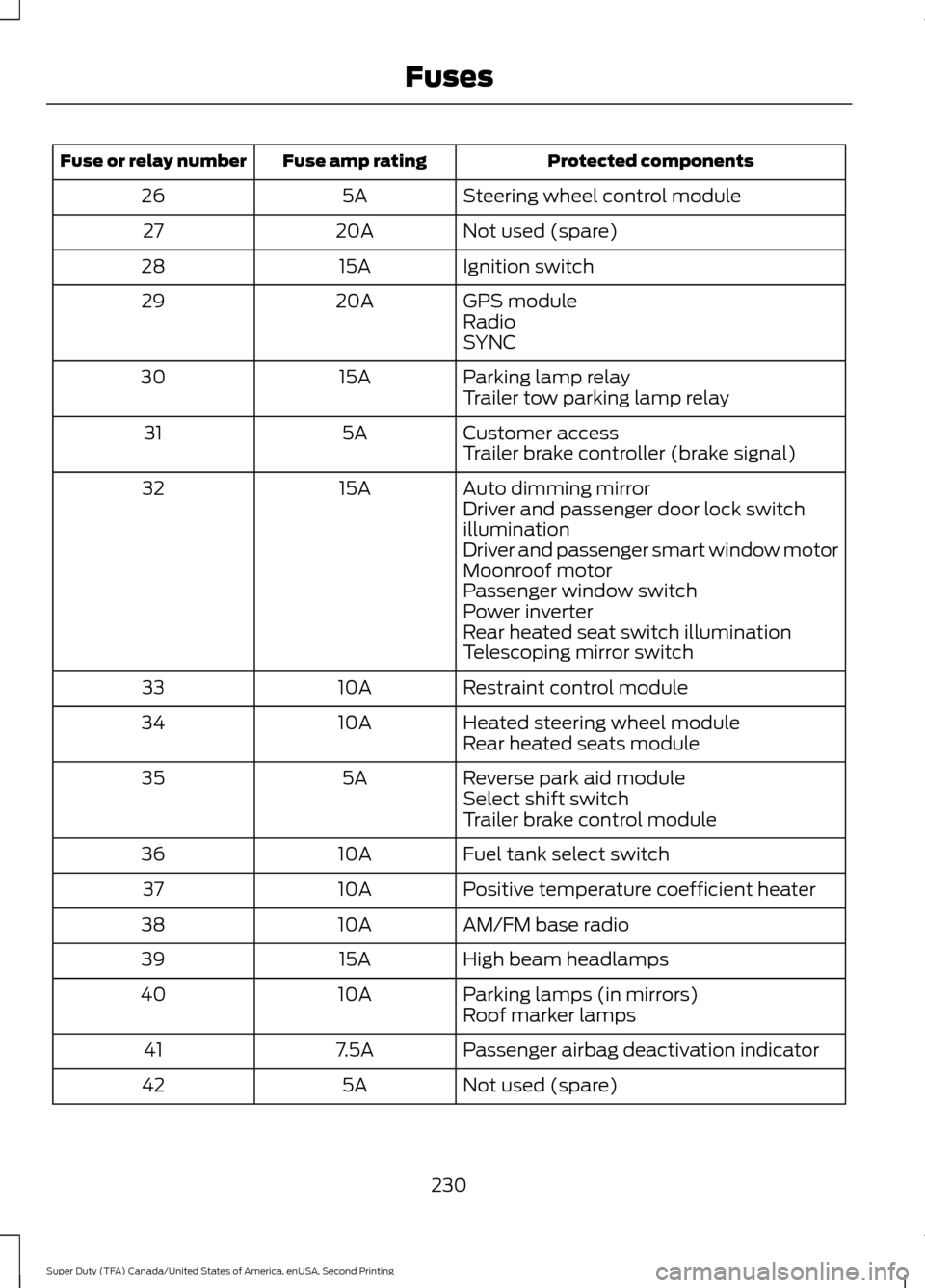
Protected components
Fuse amp rating
Fuse or relay number
Steering wheel control module
5A
26
Not used (spare)
20A
27
Ignition switch
15A
28
GPS module
20A
29
Radio
SYNC
Parking lamp relay
15A
30
Trailer tow parking lamp relay
Customer access
5A
31
Trailer brake controller (brake signal)
Auto dimming mirror
15A
32
Driver and passenger door lock switch
illumination
Driver and passenger smart window motor
Moonroof motor
Passenger window switch
Power inverter
Rear heated seat switch illumination
Telescoping mirror switch
Restraint control module
10A
33
Heated steering wheel module
10A
34
Rear heated seats module
Reverse park aid module
5A
35
Select shift switch
Trailer brake control module
Fuel tank select switch
10A
36
Positive temperature coefficient heater
10A
37
AM/FM base radio
10A
38
High beam headlamps
15A
39
Parking lamps (in mirrors)
10A
40
Roof marker lamps
Passenger airbag deactivation indicator
7.5A
41
Not used (spare)
5A
42
230
Super Duty (TFA) Canada/United States of America, enUSA, Second Printing Fuses
Page 235 of 510
GENERAL INFORMATION
Have your vehicle serviced regularly to help
maintain its roadworthiness and resale
value. There is a large network of
authorized dealers that are there to help
you with their professional servicing
expertise. We believe that their specially
trained technicians are best qualified to
service your vehicle properly and expertly.
They are supported by a wide range of
highly specialized tools developed
specifically for servicing your vehicle.
If your vehicle requires professional service,
an authorized dealer can provide the
necessary parts and service. Check your
warranty information to find out which
parts and services are covered.
Use only recommended fuels, lubricants,
fluids and service parts conforming to
specifications. Motorcraft® parts are
designed and built to provide the best
performance in your vehicle.
Precautions
•
Do not work on a hot engine.
• Make sure that nothing gets caught in
moving parts.
• Do not work on a vehicle with the
engine running in an enclosed space,
unless you are sure you have enough
ventilation.
• Keep all open flames and other burning
material (such as cigarettes) away
from the battery and all fuel related
parts.
Working with the Engine Off
1. Set the parking brake and shift to park
(P).
2. Switch off the engine.
3. Block the wheels. Working with the Engine On WARNING
To reduce the risk of vehicle damage
and/or personal burn injuries, do not
start your engine with the air cleaner
removed and do not remove it while the
engine is running. 1.
Set the parking brake and shift to park
(P).
2. Block the wheels.
OPENING AND CLOSING THE
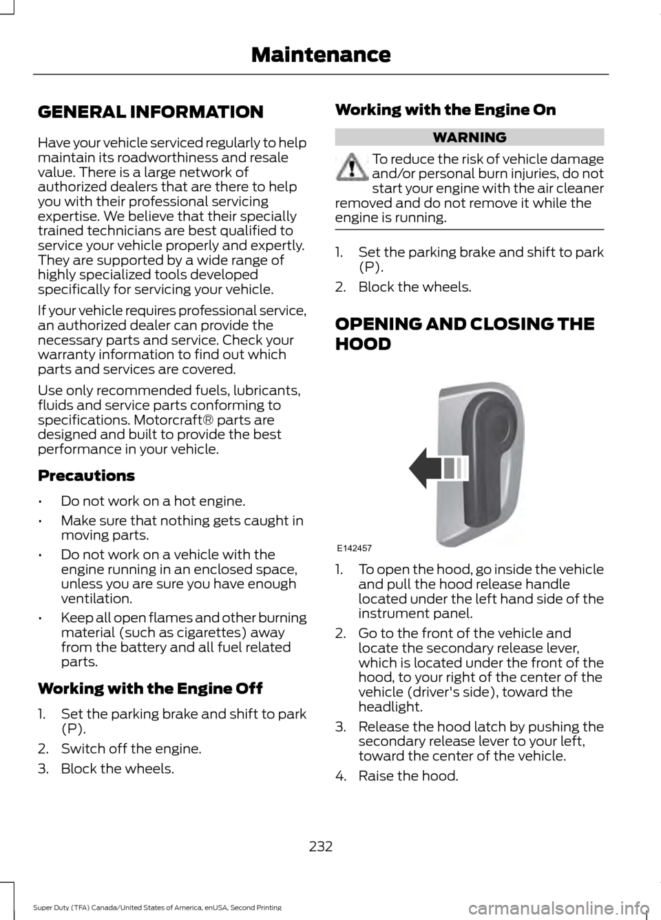
HOOD 1.
To open the hood, go inside the vehicle
and pull the hood release handle
located under the left hand side of the
instrument panel.
2. Go to the front of the vehicle and locate the secondary release lever,
which is located under the front of the
hood, to your right of the center of the
vehicle (driver's side), toward the
headlight.
3. Release the hood latch by pushing the secondary release lever to your left,
toward the center of the vehicle.
4. Raise the hood.
232
Super Duty (TFA) Canada/United States of America, enUSA, Second Printing MaintenanceE142457