2016 FORD POLICE INTERCEPTOR SEDAN clock
[x] Cancel search: clockPage 185 of 358

4. Remove two bolts that attach the air
filter assembly to the front of the
vehicle.
5. Remove the harness retaining clip by pulling up.
6. Do not disconnect the sensor. 7. Pull the air filter assembly up to
disconnect it from the seated
grommets located under the air filter
assembly.
8. Rotate the air filter assembly 90 degrees counterclockwise. Make sure
the rubber hose is still connected to the
air filter assembly.
9. Tighten the clamp.
You can now access the transmission fluid
level indicator.
Checking the fluid level
Low fluid level If the fluid level is below the MIN range of
the dipstick, add fluid to reach the hash
mark level.
Note:
If the fluid level is below the MIN
level, do not drive the vehicle. An underfill
condition may cause shift or engagement
concerns or possible damage.
Correct fluid level 182
Police Interceptor (CPH), enUSA, Edition date: 10/2015, First Printing MaintenanceE173334
654 E173400 E158842 E158843
Page 189 of 358
If you see any corrosion on the battery or
terminals, remove the cables from the
terminals and clean with a wire brush. You
can neutralize the acid with a solution of
baking soda and water.
Because your vehicle
’s engine is
electronically controlled by a computer,
some control conditions are maintained
by power from the battery. When the
battery is disconnected or a new battery
is installed, the engine must relearn its idle
and fuel trim strategy for optimum
driveability and performance. Flexible fuel
vehicles (FFV) must also relearn the
ethanol content of the fuel for optimum
driveability and performance.
To restore the settings, do the following:
1. Apply the parking brake.
2. Shift into park (P) or neutral (N).
3. Switch off all accessories.
4. Press the brake pedal and start your vehicle.
5. Run the engine until it reaches normal operating temperature. While the
engine is warming up, complete the
following: Reset the clock. See Audio
System (page 254). Reset the power
windows bounce-back feature. See
Windows and Mirrors
(page 61).
Reset the radio station presets. See
Audio System
(page 254).
6. Allow the engine to idle for at least one
minute.
7. Drive the vehicle at least 10 mi (16 km)
to completely relearn the idle trim and
fuel trim strategy.
Note: If you do not allow the engine to
relearn the idle and fuel trim strategy, the
idle quality of your vehicle may be adversely
affected until the engine computer
eventually relearns the idle trim and fuel
trim strategy. Note:
For flexible fuel vehicles, if you are
operating on E85, you may experience poor
starts or an inability to start the engine and
driveability problems until the fuel trim and
ethanol content have been relearned.
Make sure that you dispose of old batteries
in an environmentally friendly way. Seek
advice from your local authority about
recycling old batteries.
If storing your vehicle for more than 30
days without recharging the battery, we
recommend that you disconnect the
battery cables to maintain battery charge
for quick starting.
Battery Management System
(If
Equipped)
The battery management system monitors
battery conditions and takes actions to
extend battery life. If excessive battery
drain is detected, the system temporarily
disables some electrical systems to
protect the battery.
Systems included are:
• Heated rear window.
• Heated seats.
• Climate control.
• Heated steering wheel.
• Audio unit.
• Navigation system.
A message may appear in the information
displays to alert you that battery
protection actions are active. These
messages are only for notification that an
action is taking place, and not intended to
indicate an electrical problem or that the
battery requires replacement.
186
Police Interceptor (CPH), enUSA, Edition date: 10/2015, First Printing Maintenance
Page 191 of 358
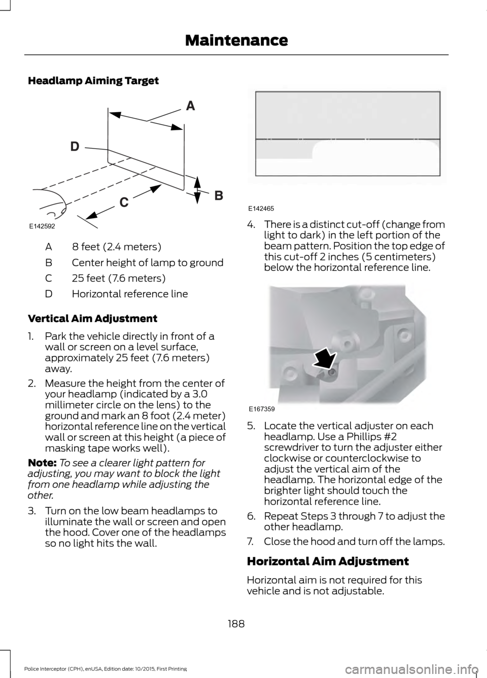
Headlamp Aiming Target
8 feet (2.4 meters)
A
Center height of lamp to ground
B
25 feet (7.6 meters)
C
Horizontal reference line
D
Vertical Aim Adjustment
1. Park the vehicle directly in front of a wall or screen on a level surface,
approximately 25 feet (7.6 meters)
away.
2. Measure the height from the center of your headlamp (indicated by a 3.0
millimeter circle on the lens) to the
ground and mark an 8 foot (2.4 meter)
horizontal reference line on the vertical
wall or screen at this height (a piece of
masking tape works well).
Note: To see a clearer light pattern for
adjusting, you may want to block the light
from one headlamp while adjusting the
other.
3. Turn on the low beam headlamps to illuminate the wall or screen and open
the hood. Cover one of the headlamps
so no light hits the wall. 4.
There is a distinct cut-off (change from
light to dark) in the left portion of the
beam pattern. Position the top edge of
this cut-off 2 inches (5 centimeters)
below the horizontal reference line. 5. Locate the vertical adjuster on each
headlamp. Use a Phillips #2
screwdriver to turn the adjuster either
clockwise or counterclockwise to
adjust the vertical aim of the
headlamp. The horizontal edge of the
brighter light should touch the
horizontal reference line.
6. Repeat Steps 3 through 7 to adjust the
other headlamp.
7. Close the hood and turn off the lamps.
Horizontal Aim Adjustment
Horizontal aim is not required for this
vehicle and is not adjustable.
188
Police Interceptor (CPH), enUSA, Edition date: 10/2015, First Printing MaintenanceE142592 E142465 E167359
Page 192 of 358
CHANGING A BULB
WARNINGS
Bulbs can become hot. Let the bulb
cool down before removing it. Failure
to do so could result in personal
injury. Switch the lamps and the ignition off.
Failure to follow this warning could
result in serious personal injury.
Use the correct specification bulb. See
Bulb Specification Chart (page 190).
Install in the reverse order unless otherwise
stated.
High-Intensity Discharge
Headlamps
These lamps operate at a high voltage. See
an authorized dealer if they fail.
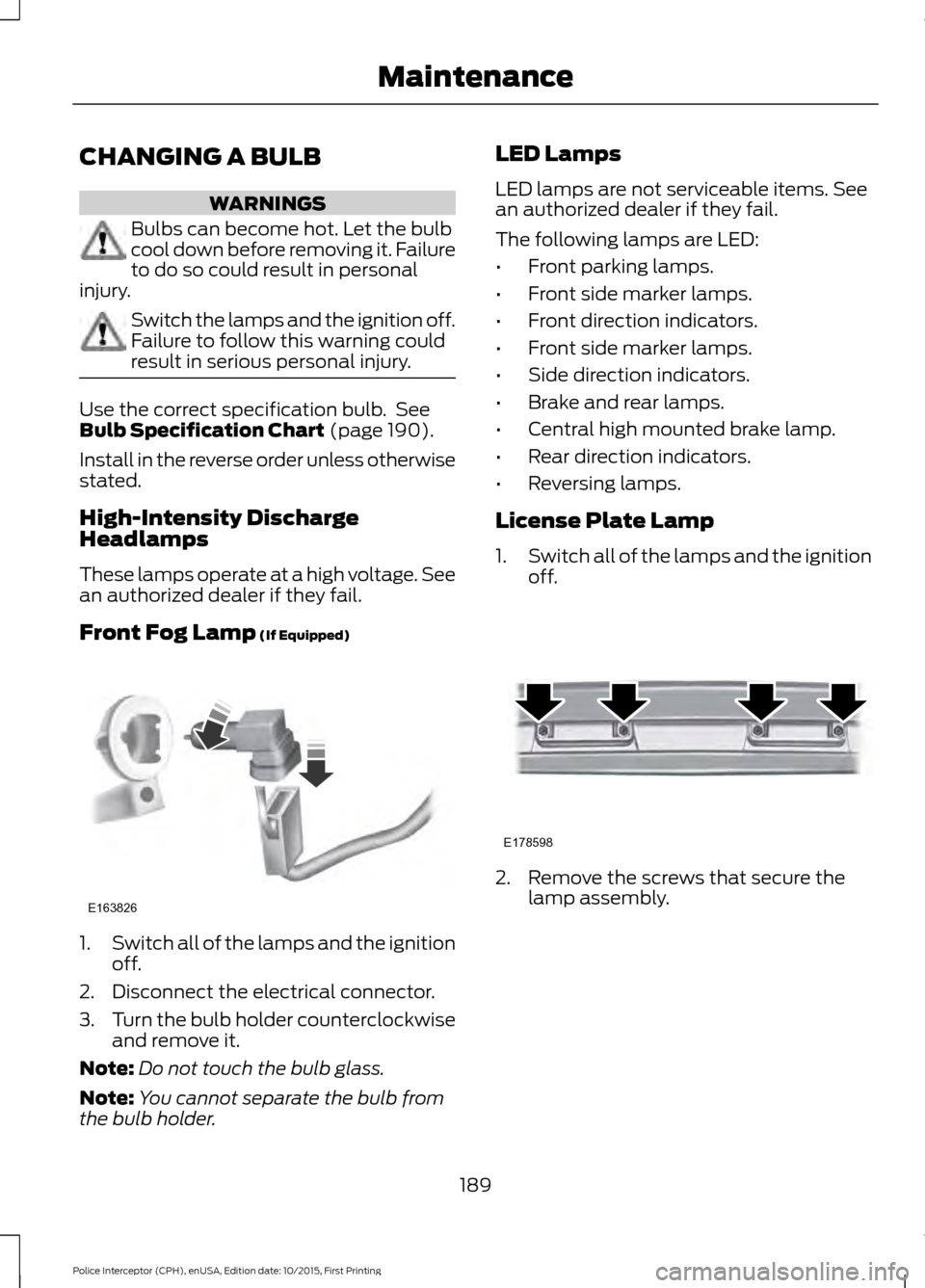
Front Fog Lamp
(If Equipped) 1.
Switch all of the lamps and the ignition
off.
2. Disconnect the electrical connector.
3. Turn the bulb holder counterclockwise
and remove it.
Note: Do not touch the bulb glass.
Note: You cannot separate the bulb from
the bulb holder. LED Lamps
LED lamps are not serviceable items. See
an authorized dealer if they fail.
The following lamps are LED:
•
Front parking lamps.
• Front side marker lamps.
• Front direction indicators.
• Front side marker lamps.
• Side direction indicators.
• Brake and rear lamps.
• Central high mounted brake lamp.
• Rear direction indicators.
• Reversing lamps.
License Plate Lamp
1. Switch all of the lamps and the ignition
off. 2. Remove the screws that secure the
lamp assembly.
189
Police Interceptor (CPH), enUSA, Edition date: 10/2015, First Printing MaintenanceE163826 E178598
Page 205 of 358
•
When inflating a tire or other objects,
use the black air hose only. Do not use
the transparent hose which is designed
for sealant application only.
• Operating the kit could cause an
electrical disturbance in radio, CD, and
DVD player operation.
What to do when a Tire Is
Punctured
A tire puncture within the tire tread area
can be repaired in two stages with the kit.
• In the first stage, the tire will be
reinflated with a sealing compound
and air. After the tire has been
reinflated, you will need to drive the
vehicle a short distance 4 mi (6 km) to
distribute the sealant in the tire.
• In the second stage, you will need to
check the tire pressure and adjust, if
necessary, to the vehicle tire inflation
pressure.
First Stage: Reinflating the Tire
with Sealing Compound and Air WARNINGS
Do not stand directly over the kit
while inflating the tire. If you notice
any unusual bulges or deformations
in the tire sidewall during inflation, stop
and call roadside assistance. If the tire does not inflate to the
recommended tire pressure within
15 minutes, stop and call roadside
assistance. Preparation: Park the vehicle in a safe, level
and secure area, away from moving traffic.
Turn the hazard lights on. Apply the parking
brake and turn the engine off. Inspect the
flat tire for visible damage. Sealant compound contains latex. To
avoid any allergic reactions, use the
non-latex gloves located in the accessory
box on the underside of the kit housing.
Do not remove any foreign object that has
pierced the tire. If a puncture is located in
the tire sidewall, stop and call roadside
assistance.
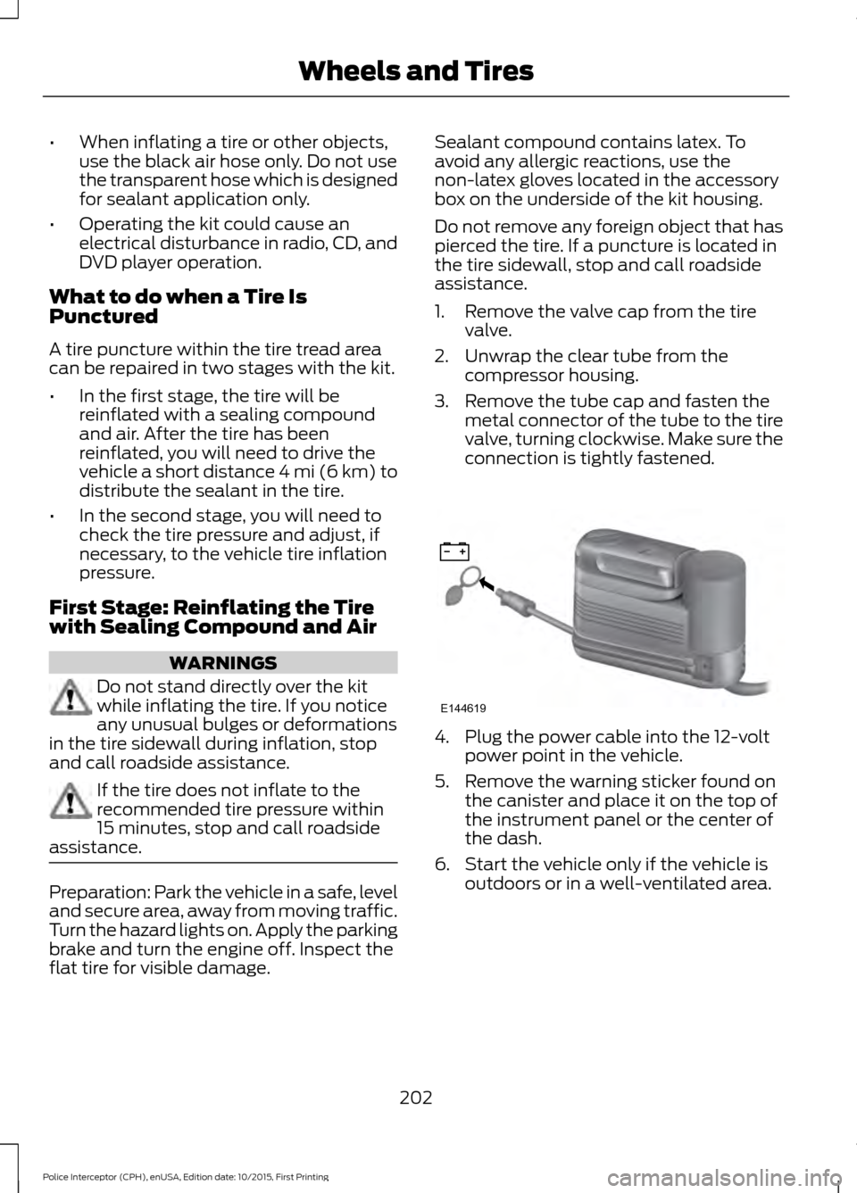
1. Remove the valve cap from the tire
valve.
2. Unwrap the clear tube from the compressor housing.
3. Remove the tube cap and fasten the metal connector of the tube to the tire
valve, turning clockwise. Make sure the
connection is tightly fastened. 4. Plug the power cable into the 12-volt
power point in the vehicle.
5. Remove the warning sticker found on the canister and place it on the top of
the instrument panel or the center of
the dash.
6. Start the vehicle only if the vehicle is outdoors or in a well-ventilated area.
202
Police Interceptor (CPH), enUSA, Edition date: 10/2015, First Printing Wheels and TiresE144619
Page 206 of 358
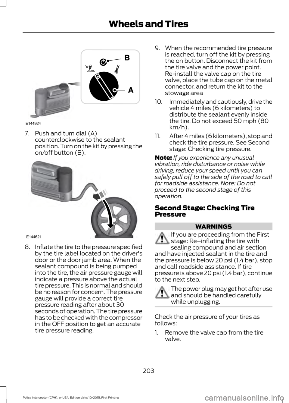
7. Push and turn dial (A)
counterclockwise to the sealant
position. Turn on the kit by pressing the
on/off button (B). 8.
Inflate the tire to the pressure specified
by the tire label located on the driver's
door or the door jamb area. When the
sealant compound is being pumped
into the tire, the air pressure gauge will
indicate a pressure above the actual
tire pressure. This is normal and should
be no reason for concern. The pressure
gauge will provide a correct tire
pressure reading after about 30
seconds of operation. The tire pressure
has to be checked with the compressor
in the OFF position to get an accurate
tire pressure reading. 9. When the recommended tire pressure
is reached, turn off the kit by pressing
the on button. Disconnect the kit from
the tire valve and the power point.
Re-install the valve cap on the tire
valve, place the tube cap on the metal
connector, and return the kit to the
stowage area
10. Immediately and cautiously, drive the
vehicle 4 miles (6 kilometers) to
distribute the sealant evenly inside
the tire. Do not exceed 50 mph (80
km/h).
11. After 4 miles (6 kilometers), stop and
check the tire pressure. See Second
stage: Checking tire pressure.
Note: If you experience any unusual
vibration, ride disturbance or noise while
driving, reduce your speed until you can
safely pull off to the side of the road to call
for roadside assistance. Note: Do not
proceed to the second stage of this
operation.
Second Stage: Checking Tire
Pressure WARNINGS
If you are proceeding from the First
stage: Re–inflating the tire with
sealing compound and air section
and have injected sealant in the tire and
the pressure is below 20 psi (1.4 bar), stop
and call roadside assistance. If tire
pressure is above 20 psi (1.4 bar), continue
to the next step. The power plug may get hot after use
and should be handled carefully
while unplugging.
Check the air pressure of your tires as
follows:
1. Remove the valve cap from the tire
valve.
203
Police Interceptor (CPH), enUSA, Edition date: 10/2015, First Printing Wheels and TiresE144924 E144621
Page 207 of 358

2. Unhook the black hose from the side
of the compressor and fasten firmly on
the valve stem by turning clockwise.
3. Push and turn the dial clockwise to the
air position. Turn on the kit by pressing
the on button. 4. Adjust the tire to the recommended
inflation pressure from the tire label
located on the driver's door or door
jamb area. The tire pressure has to be
checked with the compressor in the
OFF position to get the correct tire
pressure reading.
5. Turn the compressor off by pressing the on/off button.
6. When the tire pressure reading with the
compressor in the off position is
correct, disconnect the hose, re-install
the valve cap on the tire valve, unplug
the compressor, and return the kit to
the stowage area. What to do after the Tire has been
Sealed
After using the kit to seal your tire, you will
need to replace the sealant canister and
clear tube (hose). You can obtain and
replace sealing compound and spare parts
at an authorized Ford dealer or tire dealer.
Empty sealant bottles may be disposed of
at home. However, liquid residue from the
sealing compound should be disposed by
your local authorized Ford dealer or tire
dealer, or in accordance with local waste
disposal regulations.
Note:
After the sealing compound has been
used, the maximum vehicle speed is 50 mph
(80 km/h) and the maximum driving
distance is 120 mi (200 km). The sealed tire
should be inspected immediately.
Note: After sealant use, the tire pressure
monitoring system sensor and valve stem
on the wheel must be replaced by an
authorized Ford dealer.
You can check the tire pressure any time
within the 120 mi (200 km) by performing
the procedure from Second stage:
Checking tire pressure listed previously.
Removal of the sealant canister from
the kit 1. Unwrap the clear tube from the
compressor housing.
204
Police Interceptor (CPH), enUSA, Edition date: 10/2015, First Printing Wheels and TiresE144622 E144623
Page 229 of 358

WARNINGS
Never get underneath a vehicle that
is supported only by a jack. If the
vehicle slips off the jack, you or
someone else could be seriously injured. Do not attempt to change a tire on
the side of the vehicle close to
moving traffic. Pull far enough off the
road to avoid the danger of being hit when
operating the jack or changing the wheel. Always use the jack provided as
original equipment with your vehicle.
If using a jack other than the one
provided as original equipment with your
vehicle, make sure the jack capacity is
adequate for the vehicle weight, including
any vehicle cargo or modifications. To reduce the risk of possible serious
injury or death, do not remove the full
size spare tire from the factory
secured location. This location is necessary
to achieve police-rated 75 mph rear impact
crash-test performance. Removal
increases the risk of fuel leak in high-speed
rear impacts. Note:
Passengers should not remain in your
vehicle when the vehicle is being jacked.
Note: Jack at the specified locations to
avoid damage to the vehicle.
1. Park on a level surface, set the parking
brake and activate the hazard flashers.
2. Place the transmission in park (P) and
turn the engine off. 3. Block the diagonally opposite wheel.
4.
Lift truck cargo cover, then remove the
wingnut that secures the spare tire by
turning counterclockwise.
5. Remove the spare tire from the spare tire well.
6. Remove the wing nut bolt that secures
the jack kit by turning it
counterclockwise.
7. Remove the jack and the wrench from the bag. Fold down the wrench socket
to use to loosen the lug nuts and to
operate the jack.
8. Loosen each wheel lug nut one-half turn counterclockwise, but do not
remove them until the wheel is raised
off the ground. 9. The vehicle jacking points are shown
here, and are depicted on the warning
label on the jack. Small arrow-shaped
marks on the sills show the location of
the jacking points.
226
Police Interceptor (CPH), enUSA, Edition date: 10/2015, First Printing Wheels and TiresE142551 E145908