Page 203 of 358

GENERAL INFORMATION
A decal with tire pressure data is located
in the driver
’s door opening.
Check and set the tire pressure at the
ambient temperature in which you are
intending to drive your vehicle and when
the tires are cold.
Note: Check your tire pressures regularly to
optimize fuel economy.
Note: Use only approved wheel and tire
sizes. Using other sizes could damage your
vehicle and will make the National Type
Approval invalid.
Note: If you change the diameter of the tires
from that fitted at the factory, the
speedometer may not display the correct
speed. Take your vehicle to an authorized
dealer to have the engine management
system reprogrammed.
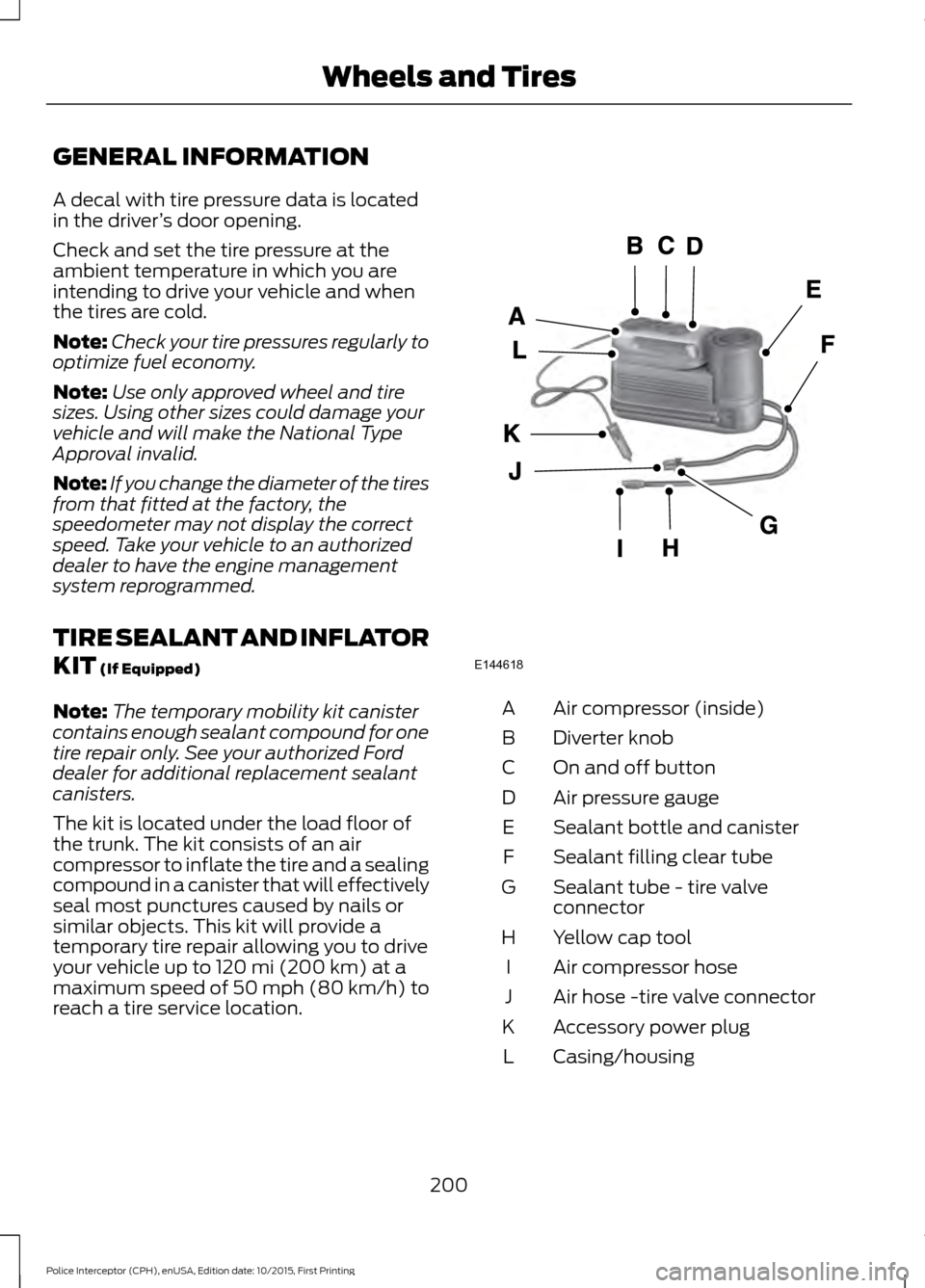
TIRE SEALANT AND INFLATOR
KIT (If Equipped)
Note: The temporary mobility kit canister
contains enough sealant compound for one
tire repair only. See your authorized Ford
dealer for additional replacement sealant
canisters.
The kit is located under the load floor of
the trunk. The kit consists of an air
compressor to inflate the tire and a sealing
compound in a canister that will effectively
seal most punctures caused by nails or
similar objects. This kit will provide a
temporary tire repair allowing you to drive
your vehicle up to
120 mi (200 km) at a
maximum speed of 50 mph (80 km/h) to
reach a tire service location. Air compressor (inside)
A
Diverter knob
B
On and off button
C
Air pressure gauge
D
Sealant bottle and canister
E
Sealant filling clear tube
F
Sealant tube - tire valve
connector
G
Yellow cap tool
H
Air compressor hose
I
Air hose -tire valve connector
J
Accessory power plug
K
Casing/housing
L
200
Police Interceptor (CPH), enUSA, Edition date: 10/2015, First Printing Wheels and TiresE144618
Page 204 of 358

General Information
WARNING
Failure to follow these guidelines
could result in an increased risk of
loss of vehicle control, injury or death.
Note:
Do not use the kit if a tire has become
severely damaged by driving the vehicle with
a tire that has insufficient air pressure. Only
punctured areas located within the tire tread
can be sealed with the kit.
Do not attempt to repair punctures larger
than ¼ inch (6 millimeters) or damage to
the tire's sidewall. The tire may not
completely seal.
Loss of air pressure may adversely affect
tire performance. For this reason:
Note: Do not drive the vehicle above
50 mph (80 km/h).
Note: Do not drive further than
120 mi
(200 km). Drive only to the closest
authorized Ford dealer or tire repair shop to
have your tire inspected.
• Drive carefully and avoid abrupt
steering maneuvers.
• Periodically monitor tire inflation
pressure in the affected tire. If the tire
is losing pressure, have the vehicle
towed.
• Read the information in the Tips for
Use of the Kit section to make sure safe
operation of the kit and your vehicle.
Tips for Use of the Kit
Read the following list of tips to ensure
safe operation of the kit: •
Before operating the kit, make sure
your vehicle is safely off the road and
away from moving traffic. Turn on the
hazard lights.
• Always set the parking brake to ensure
the vehicle does not move
unexpectedly.
• Do not remove any foreign objects,
such as nails or screws, from the tire.
• When using the kit, leave the engine
running (only if the vehicle is outdoors
or in a well-ventilated area) so the
compressor does not drain the vehicle
battery.
• Do not allow the compressor to
operate continuously for more than 15
minutes. This will help prevent the
compressor from overheating.
• Never leave the kit unattended when
it is operating.
• Sealant compound contains latex.
Make sure that you use the non-latex
gloves provided to avoid an allergic
reaction.
• Keep the kit away from children.
• Only use the kit when the ambient
temperature is between
-22°F (-30°C)
and 158°F (70°C).
• Only use the sealing compound before
the use by date. The use by date is on
the lower right hand corner of the label
located on the sealant canister
(bottle). Check the use by date
regularly and replace the canister after
four years.
• Do not store the kit unsecured inside
the passenger compartment of the
vehicle as it may cause injury during a
sudden stop or crash. Always store the
kit in its original location.
• After sealant use, the tire pressure
monitoring system sensor and valve
stem on the wheel must be replaced
by an authorized Ford dealer.
201
Police Interceptor (CPH), enUSA, Edition date: 10/2015, First Printing Wheels and Tires
Page 205 of 358

•
When inflating a tire or other objects,
use the black air hose only. Do not use
the transparent hose which is designed
for sealant application only.
• Operating the kit could cause an
electrical disturbance in radio, CD, and
DVD player operation.
What to do when a Tire Is
Punctured
A tire puncture within the tire tread area
can be repaired in two stages with the kit.
• In the first stage, the tire will be
reinflated with a sealing compound
and air. After the tire has been
reinflated, you will need to drive the
vehicle a short distance 4 mi (6 km) to
distribute the sealant in the tire.
• In the second stage, you will need to
check the tire pressure and adjust, if
necessary, to the vehicle tire inflation
pressure.
First Stage: Reinflating the Tire
with Sealing Compound and Air WARNINGS
Do not stand directly over the kit
while inflating the tire. If you notice
any unusual bulges or deformations
in the tire sidewall during inflation, stop
and call roadside assistance. If the tire does not inflate to the
recommended tire pressure within
15 minutes, stop and call roadside
assistance. Preparation: Park the vehicle in a safe, level
and secure area, away from moving traffic.
Turn the hazard lights on. Apply the parking
brake and turn the engine off. Inspect the
flat tire for visible damage. Sealant compound contains latex. To
avoid any allergic reactions, use the
non-latex gloves located in the accessory
box on the underside of the kit housing.
Do not remove any foreign object that has
pierced the tire. If a puncture is located in
the tire sidewall, stop and call roadside
assistance.
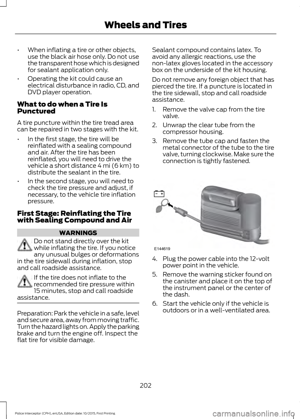
1. Remove the valve cap from the tire
valve.
2. Unwrap the clear tube from the compressor housing.
3. Remove the tube cap and fasten the metal connector of the tube to the tire
valve, turning clockwise. Make sure the
connection is tightly fastened. 4. Plug the power cable into the 12-volt
power point in the vehicle.
5. Remove the warning sticker found on the canister and place it on the top of
the instrument panel or the center of
the dash.
6. Start the vehicle only if the vehicle is outdoors or in a well-ventilated area.
202
Police Interceptor (CPH), enUSA, Edition date: 10/2015, First Printing Wheels and TiresE144619
Page 229 of 358

WARNINGS
Never get underneath a vehicle that
is supported only by a jack. If the
vehicle slips off the jack, you or
someone else could be seriously injured. Do not attempt to change a tire on
the side of the vehicle close to
moving traffic. Pull far enough off the
road to avoid the danger of being hit when
operating the jack or changing the wheel. Always use the jack provided as
original equipment with your vehicle.
If using a jack other than the one
provided as original equipment with your
vehicle, make sure the jack capacity is
adequate for the vehicle weight, including
any vehicle cargo or modifications. To reduce the risk of possible serious
injury or death, do not remove the full
size spare tire from the factory
secured location. This location is necessary
to achieve police-rated 75 mph rear impact
crash-test performance. Removal
increases the risk of fuel leak in high-speed
rear impacts. Note:
Passengers should not remain in your
vehicle when the vehicle is being jacked.
Note: Jack at the specified locations to
avoid damage to the vehicle.
1. Park on a level surface, set the parking
brake and activate the hazard flashers.
2. Place the transmission in park (P) and
turn the engine off. 3. Block the diagonally opposite wheel.
4.
Lift truck cargo cover, then remove the
wingnut that secures the spare tire by
turning counterclockwise.
5. Remove the spare tire from the spare tire well.
6. Remove the wing nut bolt that secures
the jack kit by turning it
counterclockwise.
7. Remove the jack and the wrench from the bag. Fold down the wrench socket
to use to loosen the lug nuts and to
operate the jack.
8. Loosen each wheel lug nut one-half turn counterclockwise, but do not
remove them until the wheel is raised
off the ground. 9. The vehicle jacking points are shown
here, and are depicted on the warning
label on the jack. Small arrow-shaped
marks on the sills show the location of
the jacking points.
226
Police Interceptor (CPH), enUSA, Edition date: 10/2015, First Printing Wheels and TiresE142551 E145908
Page 232 of 358
ENGINE SPECIFICATIONS - 2.0L ECOBOOST™
2.0L EcoBoost engine
Engine
122
Cubic inches
9.3:1
Compression ratio
Coil on plug
Ignition system
0.027-0.031 in. (0.70-0.80 mm)
Spark plug gap
1-3-4-2
Firing order
Drivebelt Routing
2.0L engine A.
The long drivebelt is on the first pulley
groove closest to the engine.
B. The short drivebelt is on the second
pulley groove farthest from the engine.
ENGINE SPECIFICATIONS - 3.5L DURATEC 3.5L V6
Engine
214
Cubic inches
1-4-2-5-3-6
Firing order
Coil on plug
Ignition system
0.049 - 0.053 in (1.25 mm - 1.35 mm)
Spark plug gap
10.8:1
Compression ratio
229
Police Interceptor (CPH), enUSA, Edition date: 10/2015, First Printing Capacities and SpecificationsE161383
A
B
Page 233 of 358
Drivebelt Routing
3.5L EngineENGINE SPECIFICATIONS - 3.5L ECOBOOST™
3.5L EcoBoost
Engine
214
Cubic inches
1-4-2-5-3-6
Firing order
Coil on plug
Ignition system
0.030–0.033 in (0.75–0.85 mm)
Spark plug gap
10.0:1
Compression ratio
Drivebelt Routing
3.5L EcoBoost Engine 230
Police Interceptor (CPH), enUSA, Edition date: 10/2015, First Printing Capacities and SpecificationsE191904 E191904
Page 234 of 358
ENGINE SPECIFICATIONS - 3.7L
3.7L V6
Engine
227
Cubic inches
1-4-2-5-3-6
Firing order
Coil on plug
Ignition system
0.049 - 0.053 in (1.25 - 1.35 mm)
Spark plug gap
10.5:1
Compression ratio
Drivebelt Routing
3.7L Engine MOTORCRAFT PARTS - 2.0L ECOBOOST™
Motorcraft part number
Component
FA-1884
Air filter element
FL-910-S
Oil filter
BXT-65-750
Battery
SP-537
Spark plugs
FP68
Cabin air filter
WW-2601 (driver side)
Windshield wiper blade
231
Police Interceptor (CPH), enUSA, Edition date: 10/2015, First Printing Capacities and SpecificationsE191904
Page 235 of 358
Motorcraft part number
Component
WW-2043 (passenger side)
We recommend Motorcraft replacement parts available at your Ford dealer or at
fordparts.com for scheduled maintenance. These parts meet or exceed Ford Motor
Company ’s specifications and are engineered for your vehicle. Use of other parts may
impact vehicle performance, emissions and durability. Your warranty may be void for any
damage related to use of other parts.
If a Motorcraft oil filter is not available, use an oil filter that meets industry performance
specification SAE/USCAR-36.
For spark plug replacement, contact an authorized dealer. Replace the spark plugs at the
appropriate intervals. See Normal Scheduled Maintenance (page 313).
232
Police Interceptor (CPH), enUSA, Edition date: 10/2015, First Printing Capacities and Specifications