2016 FORD F450 SUPER DUTY sensor
[x] Cancel search: sensorPage 111 of 507
ActionMessage
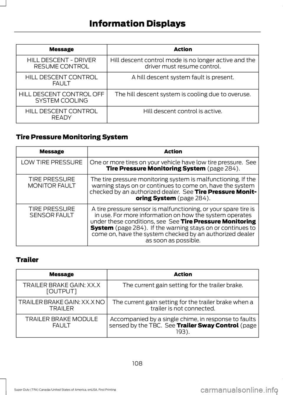
Hill descent control mode is no longer active and thedriver must resume control.HILL DESCENT - DRIVERRESUME CONTROL
A hill descent system fault is present.HILL DESCENT CONTROLFAULT
The hill descent system is cooling due to overuse.HILL DESCENT CONTROL OFFSYSTEM COOLING
Hill descent control is active.HILL DESCENT CONTROLREADY
Tire Pressure Monitoring System
ActionMessage
One or more tires on your vehicle have low tire pressure. SeeTire Pressure Monitoring System (page 284).LOW TIRE PRESSURE
The tire pressure monitoring system is malfunctioning. If thewarning stays on or continues to come on, have the systemchecked by an authorized dealer. See Tire Pressure Monit-oring System (page 284).
TIRE PRESSUREMONITOR FAULT
A tire pressure sensor is malfunctioning, or your spare tire isin use. For more information on how the system operatesunder these conditions, see See Tire Pressure MonitoringSystem (page 284). If the warning stays on or continues tocome on, have the system checked by an authorized dealeras soon as possible.
TIRE PRESSURESENSOR FAULT
Trailer
ActionMessage
The current gain setting for the trailer brake.TRAILER BRAKE GAIN: XX.X[OUTPUT]
The current gain setting for the trailer brake when atrailer is not connected.TRAILER BRAKE GAIN: XX.X NOTRAILER
Accompanied by a single chime, in response to faultssensed by the TBC. See Trailer Sway Control (page193).
TRAILER BRAKE MODULEFAULT
108
Super Duty (TFA) Canada/United States of America, enUSA, First Printing
Information Displays
Page 141 of 507
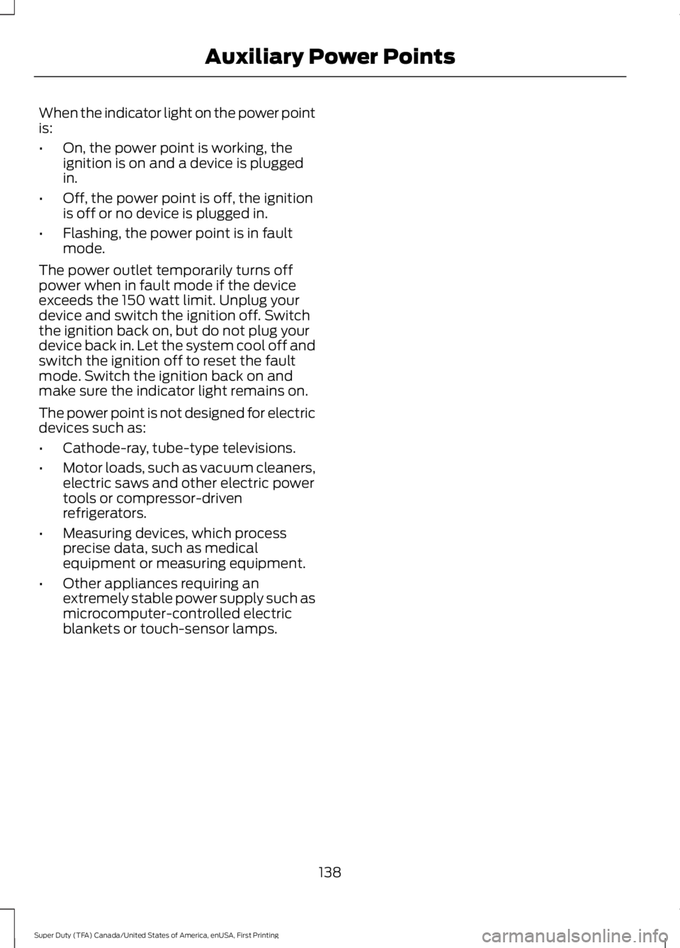
When the indicator light on the power pointis:
•On, the power point is working, theignition is on and a device is pluggedin.
•Off, the power point is off, the ignitionis off or no device is plugged in.
•Flashing, the power point is in faultmode.
The power outlet temporarily turns offpower when in fault mode if the deviceexceeds the 150 watt limit. Unplug yourdevice and switch the ignition off. Switchthe ignition back on, but do not plug yourdevice back in. Let the system cool off andswitch the ignition off to reset the faultmode. Switch the ignition back on andmake sure the indicator light remains on.
The power point is not designed for electricdevices such as:
•Cathode-ray, tube-type televisions.
•Motor loads, such as vacuum cleaners,electric saws and other electric powertools or compressor-drivenrefrigerators.
•Measuring devices, which processprecise data, such as medicalequipment or measuring equipment.
•Other appliances requiring anextremely stable power supply such asmicrocomputer-controlled electricblankets or touch-sensor lamps.
138
Super Duty (TFA) Canada/United States of America, enUSA, First Printing
Auxiliary Power Points
Page 174 of 507
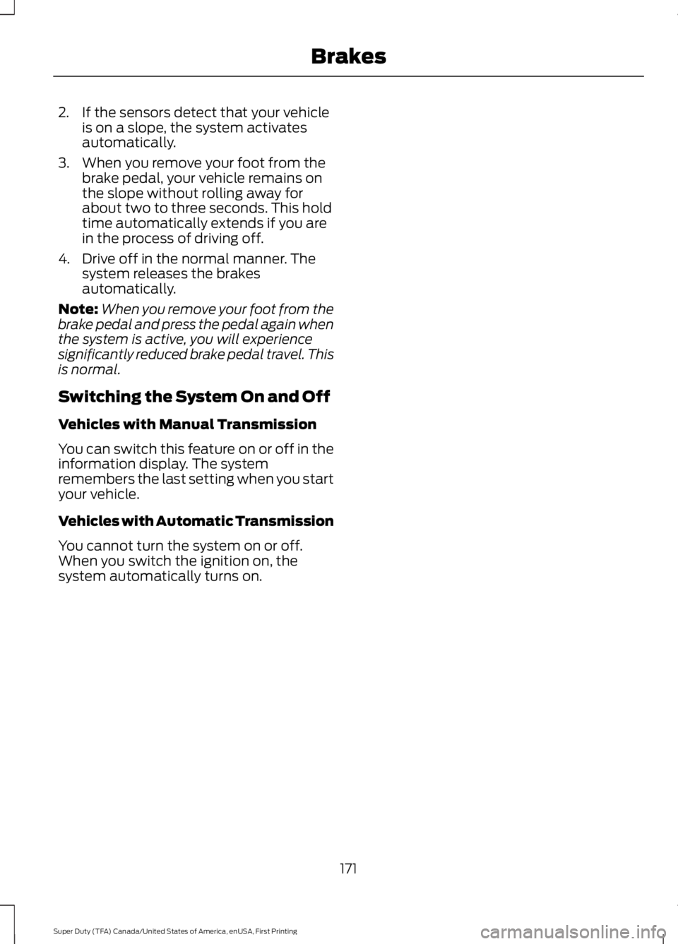
2. If the sensors detect that your vehicleis on a slope, the system activatesautomatically.
3. When you remove your foot from thebrake pedal, your vehicle remains onthe slope without rolling away forabout two to three seconds. This holdtime automatically extends if you arein the process of driving off.
4. Drive off in the normal manner. Thesystem releases the brakesautomatically.
Note:When you remove your foot from thebrake pedal and press the pedal again whenthe system is active, you will experiencesignificantly reduced brake pedal travel. Thisis normal.
Switching the System On and Off
Vehicles with Manual Transmission
You can switch this feature on or off in theinformation display. The systemremembers the last setting when you startyour vehicle.
Vehicles with Automatic Transmission
You cannot turn the system on or off.When you switch the ignition on, thesystem automatically turns on.
171
Super Duty (TFA) Canada/United States of America, enUSA, First Printing
Brakes
Page 177 of 507
PRINCIPLE OF OPERATION
WARNINGS
Vehicle modifications involvingbraking system, aftermarket roofracks, suspension, steering system,tire construction and wheel and tire sizemay change the handling characteristicsof your vehicle and may adversely affectthe performance of the AdvanceTracsystem. In addition, installing any stereoloudspeakers may interfere with andadversely affect the AdvanceTrac system.Install any aftermarket stereo loudspeakeras far as possible from the front centerconsole, the tunnel, and the front seats inorder to minimize the risk of interfering withthe AdvanceTrac sensors. Reducing theeffectiveness of the AdvanceTrac systemcould lead to an increased risk of loss ofvehicle control, vehicle rollover, personalinjury and death.
Remember that even advancedtechnology cannot defy the laws ofphysics. It’s always possible to losecontrol of a vehicle due to inappropriatedriver input for the conditions. Aggressivedriving on any road condition can causeyou to lose control of your vehicleincreasing the risk of personal injury orproperty damage. Activation of theAdvanceTrac system is an indication thatat least some of the tires have exceededtheir ability to grip the road; this couldreduce the operator’s ability to control thevehicle potentially resulting in a loss ofvehicle control, vehicle rollover, personalinjury and death. If your AdvanceTracsystem activates, SLOW DOWN.
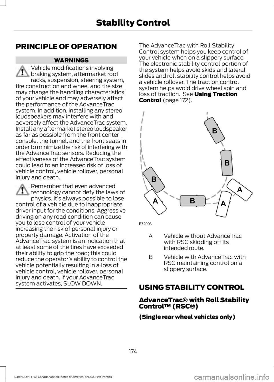
The AdvanceTrac with Roll StabilityControl system helps you keep control ofyour vehicle when on a slippery surface.The electronic stability control portion ofthe system helps avoid skids and lateralslides and roll stability control helps avoida vehicle rollover. The traction controlsystem helps avoid drive wheel spin andloss of traction. See Using TractionControl (page 172).
Vehicle without AdvanceTracwith RSC skidding off itsintended route.
A
Vehicle with AdvanceTrac withRSC maintaining control on aslippery surface.
B
USING STABILITY CONTROL
AdvanceTrac® with Roll StabilityControl™ (RSC®)
(Single rear wheel vehicles only)
174
Super Duty (TFA) Canada/United States of America, enUSA, First Printing
Stability ControlE72903A
AA
B
BB
B
Page 182 of 507
PARKING AID (If Equipped)
WARNINGS
The system does not relieve you ofyour responsibility to drive with duecare and attention.
If your vehicles has a non-Fordapproved trailer tow module thesystem may not correctly detectobjects.
The sensors may not detect objectsin heavy rain or other conditions thatcause disruptive reflections.
The sensors may not detect objectswith surfaces that absorb ultrasonicwaves.
The system does not detect objectsthat are moving away from yourvehicle. They will only be detectedshortly after they start to move towardyour vehicle.
Take particular care when reversingwith a tow ball arm or a rear fittedaccessory. For example, a bicyclecarrier. The rear parking aid will onlyindicate the approximate distance fromthe rear bumper to an object.
Note:If you use a high pressure spray towash your vehicle, only spray the sensorsbriefly from a distance not less than 8 in(20 cm).
Note:If your vehicle has a tow ball arm, thesystem is turned off automatically whentrailer lamps (or lighting boards) areconnected to the 13-pin socket through aFord approved trailer tow module.
Note:Keep the sensors free from dirt, iceor snow. Do not clean with sharp objects.
Note:The system may emit false alerts ifit detects a signal using the same frequencyas the sensors or if your vehicle is fullyloaded.
Note:The outer sensors may detect theside walls of a garage. If the distancebetween the outer sensors and the side wallremains constant for three seconds, thealert will turn off. As you continue the innersensors will detect objects directly behindyour vehicle.
Rear Parking Aid
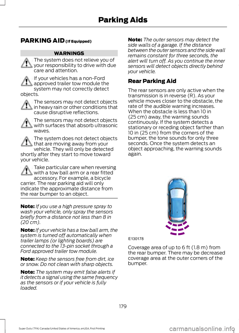
The rear sensors are only active when thetransmission is in reverse (R). As yourvehicle moves closer to the obstacle, therate of the audible warning increases.When the obstacle is less than 10 in(25 cm) away, the warning soundscontinuously. If the system detects astationary or receding object farther than10 in (25 cm) from the corners of thebumper, the tone sounds for only threeseconds. Once the system detects anobject approaching, the warning soundsagain.
Coverage area of up to 6 ft (1.8 m) fromthe rear bumper. There may be decreasedcoverage area at the outer corners of thebumper.
179
Super Duty (TFA) Canada/United States of America, enUSA, First Printing
Parking AidsE130178
Page 213 of 507
•The tire air pressures recommendedfor general driving are on the vehicle’sSafety Certification Label. Themaximum cold inflation pressure forthe tire and associated load rating ison the tire sidewall. Tire air pressuremay require re-adjustment within thesepressure limits to accommodate theadditional weight of the snowplowinstallation.
•Federal and some local regulationsrequire additional exterior lamps forsnowplow-equipped vehicles. Consultyour authorized dealer for additionalinformation.
Operating the Vehicle with theSnowplow Attached
Note:Do not use your vehicle for snowremoval until you have driven at least500 mi (800 km).
Ford recommends vehicle speed does notexceed 45 mph (72 km/h) whensnowplowing.
The attached snowplow blade restrictsairflow to the radiator, and may cause theengine to run at a higher temperature:Attention to engine temperature isespecially important when outsidetemperatures are above freezing. Anglethe blade to maximize airflow to theradiator and monitor engine temperatureto determine whether a left or right angleprovides the best performance.
Follow the severe duty schedule in yourScheduled Maintenance information forengine oil and transmission fluid changeintervals.
Snowplowing with your AirbagEquipped Vehicle
WARNINGS
Do not attempt to service, repair, ormodify the airbag supplementalrestraint system (SRS) or its fuses.Contact an authorized dealer.
Additional equipment such assnowplow equipment may affect theperformance of the airbag sensorsincreasing the risk of injury. Please refer tothe Body Builders Layout Book forinstructions about the appropriateinstallation of additional equipment.
All occupants of the vehicle,including the driver, should alwaysproperly wear their safety belts, evenwhen provided with an airbagsupplemental restraint system (SRS).
Your vehicle is equipped with a driver andpassenger airbag supplemental restraintsystem. The supplemental restraint systemwill activate in certain frontal and offsetfrontal collisions when the vehicle sustainssufficient frontal deceleration.
Careless or high speed driving whileplowing snow that results in sufficientvehicle decelerations can deploy theairbag. Such driving also increases the riskof accidents
Never remove or defeat the trippingmechanisms designed into the snowremoval equipment by its manufacturer.Doing so may cause damage to the vehicleand the snow removal equipment as wellas possible airbag deployment.
Engine temperature while plowing
When driving with a plow, your engine mayrun at a higher temperature than normalbecause the attached snowplow blade willrestrict airflow to the radiator.
210
Super Duty (TFA) Canada/United States of America, enUSA, First Printing
Driving Hints
Page 257 of 507
CHANGING THE ENGINE AIR
FILTER
WARNING
To reduce the risk of vehicle damageand personal burn injuries, do notstart your engine with the air cleanerremoved and do not remove it while theengine is running.
Note: Failure to use the correct air filterelement may result in severe enginedamage. Resulting component damagemay not be covered by the vehicle Warranty.
When changing the air filter element, useonly the air filter element listed. SeeMotorcraft Parts (page 304).
Change the air filter element at the correctinterval. See Scheduled Maintenance(page 453).
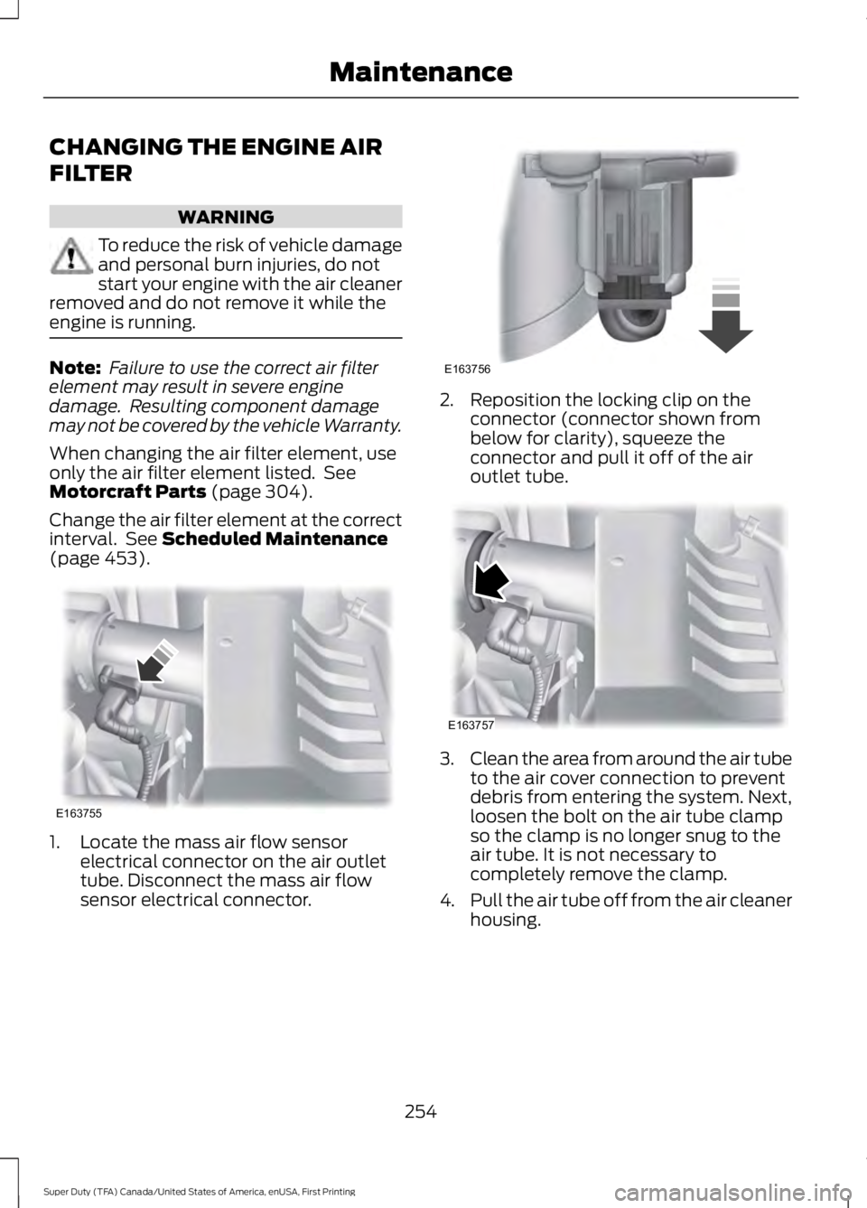
1. Locate the mass air flow sensorelectrical connector on the air outlettube. Disconnect the mass air flowsensor electrical connector.
2. Reposition the locking clip on theconnector (connector shown frombelow for clarity), squeeze theconnector and pull it off of the airoutlet tube.
3.Clean the area from around the air tubeto the air cover connection to preventdebris from entering the system. Next,loosen the bolt on the air tube clampso the clamp is no longer snug to theair tube. It is not necessary tocompletely remove the clamp.
4.Pull the air tube off from the air cleanerhousing.
254
Super Duty (TFA) Canada/United States of America, enUSA, First Printing
MaintenanceE163755 E163756 E163757
Page 258 of 507
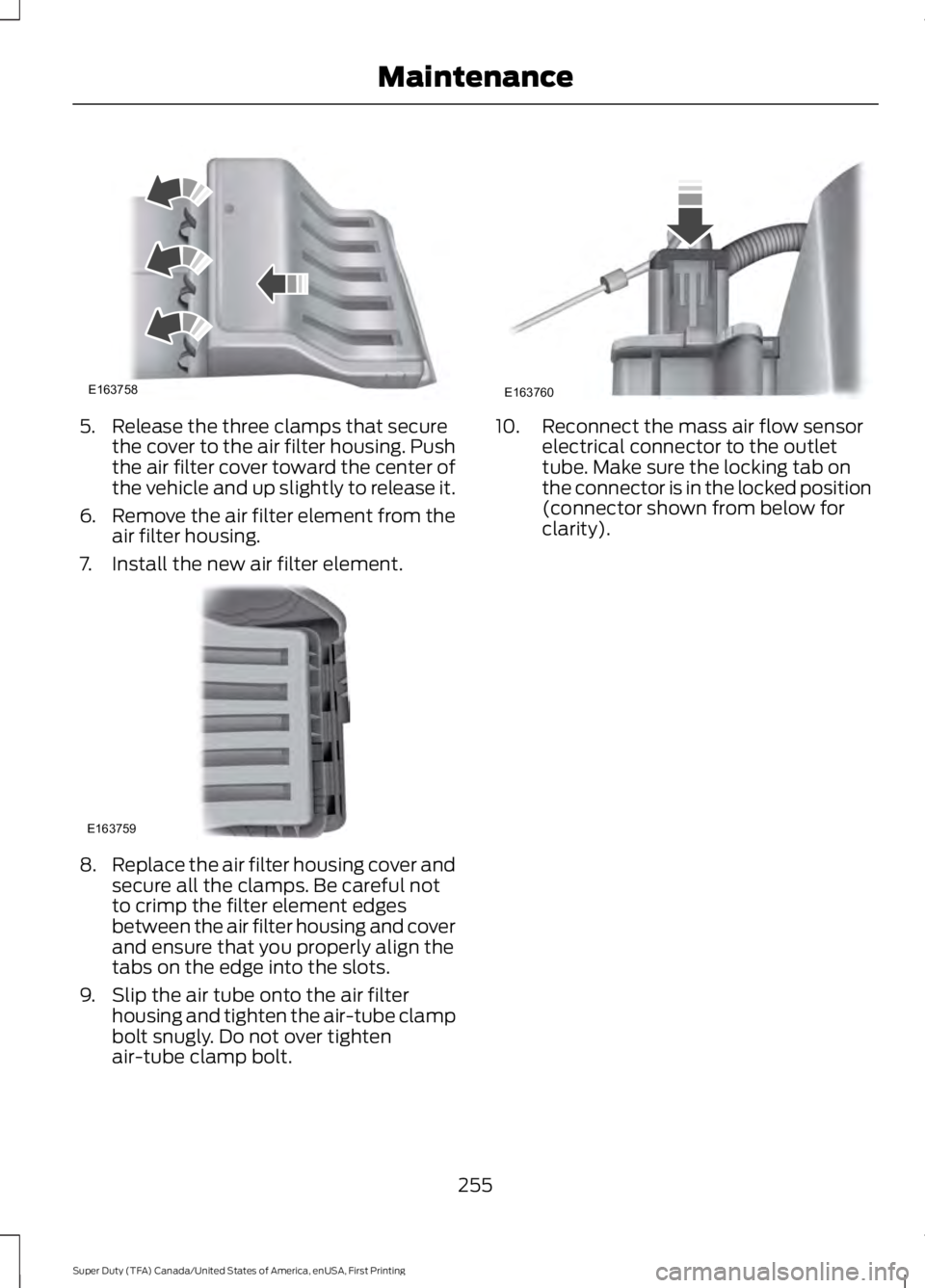
5. Release the three clamps that securethe cover to the air filter housing. Pushthe air filter cover toward the center ofthe vehicle and up slightly to release it.
6.Remove the air filter element from theair filter housing.
7. Install the new air filter element.
8.Replace the air filter housing cover andsecure all the clamps. Be careful notto crimp the filter element edgesbetween the air filter housing and coverand ensure that you properly align thetabs on the edge into the slots.
9. Slip the air tube onto the air filterhousing and tighten the air-tube clampbolt snugly. Do not over tightenair-tube clamp bolt.
10. Reconnect the mass air flow sensorelectrical connector to the outlettube. Make sure the locking tab onthe connector is in the locked position(connector shown from below forclarity).
255
Super Duty (TFA) Canada/United States of America, enUSA, First Printing
MaintenanceE163758 E163759 E163760