2016 FORD F250 brake
[x] Cancel search: brakePage 180 of 507

PRINCIPLE OF OPERATION
WARNINGS
Hill descent control cannot control
descent in all surface conditions and
circumstances, such as ice or
extremely steep grades. Hill descent
control is a driver assist system and cannot
substitute for good judgment by the driver.
Failure to do so may result in loss of vehicle
control, crash or serious injury. Hill descent control does not provide
hill hold at zero miles per hour (0
kilometers per hour). When stopped,
the parking brake must be applied or the
vehicle must be placed in P (Park) or it
may roll away. Hill descent control allows the driver to set
and maintain vehicle speed while
descending steep grades in various surface
conditions.
Hill descent control can maintain vehicle
speeds on downhill grades between 2 mph
(3 km/h) and 12 mph (20 km/h). Above 20
mph (32 km/h), the system remains
armed, but descent speed cannot be set
or maintained.
Hill descent control requires a cooling
down interval after a period of sustained
use. The amount of time that the feature
can remain active before cooling varies
with conditions. The system will provide a
warning in the message center and a chime
will sound when the system is about to
disengage for cooling. At this time,
manually apply the brakes as needed to
maintain descent speed. USING HILL DESCENT
CONTROL Press and release the hill
descent button located on the
instrument panel. A light in the
cluster will illuminate and a chime will
sound when this feature is activated.
To increase descent speed, press the
accelerator pedal until the desired speed
is reached. To decrease descent speed,
press the brake pedal until the desired
speed is reached.
Whether accelerating or decelerating, once
the desired descent speed is reached,
remove your feet from the pedals and the
chosen vehicle speed will be maintained.
Note: Noise from the ABS pump motor may
be observed during hill descent control
operation. This is a normal characteristic of
the ABS and should be no reason for
concern.
Hill descent modes
• At speeds below 20 mph (32 km/h):
When the Hill Descent Control switch
is pressed and Hill Descent Control is
active, the Hill Descent Control telltale
will flash.
• At speeds below 20 mph (32 km/h):
When the Hill Descent Control switch
is pressed and conditions are not
correct for hill descent activation, the
Hill Descent Control system will be
enabled, the Hill Descent Control
telltale will be solid and a message will
display in the information display.
• At speeds above 20 mph (32 km/h):
When the Hill Descent Control switch
is pressed, the Hill Descent Control
system will be enabled, the telltale in
the cluster will not be illuminated and
a message will be displayed in the
information display.
177
Super Duty (TFA) Canada/United States of America, enUSA, First Printing Terrain Response
(If Equipped)E163957
Page 186 of 507

PRINCIPLE OF OPERATION
Cruise control lets you maintain a set
speed without keeping your foot on the
accelerator pedal. You can use cruise
control when your vehicle speed is greater
than 20 mph (30 km/h).
USING CRUISE CONTROL WARNINGS
Do not use cruise control in heavy
traffic, on winding roads or when the
road surface is slippery. This could
result in loss of vehicle control, serious
injury or death. When you are going downhill, your
vehicle speed may increase above
the set speed. The system will not
apply the brakes. Change down a gear to
assist the system in maintaining the set
speed. Failure to do so could result in loss
of vehicle control, serious injury or death. Note:
Cruise control will disengage if the
vehicle speed decreases more than 10 mph
(16 km/h) below your set speed while
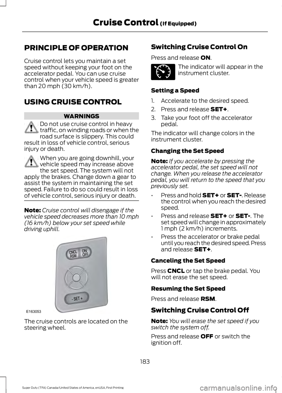
driving uphill. The cruise controls are located on the
steering wheel. Switching Cruise Control On
Press and release
ON. The indicator will appear in the
instrument cluster.
Setting a Speed
1. Accelerate to the desired speed.
2. Press and release
SET+.
3. Take your foot off the accelerator pedal.
The indicator will change colors in the
instrument cluster.
Changing the Set Speed
Note: If you accelerate by pressing the
accelerator pedal, the set speed will not
change. When you release the accelerator
pedal, you will return to the speed that you
previously set.
• Press and hold SET+ or SET-. Release
the control when you reach the desired
speed.
• Press and release
SET+ or SET-. The
set speed will change in approximately
1 mph (2 km/h) increments.
• Press the accelerator or brake pedal
until you reach the desired speed. Press
and release
SET+.
Canceling the Set Speed
Press
CNCL or tap the brake pedal. You
will not erase the set speed.
Resuming the Set Speed
Press and release
RSM.
Switching Cruise Control Off
Note: You will erase the set speed if you
switch the system off.
Press and release
OFF or switch the
ignition off.
183
Super Duty (TFA) Canada/United States of America, enUSA, First Printing Cruise Control
(If Equipped)E163053 E71340
Page 192 of 507

GCW (Gross Combined Weight)
- is the Gross Vehicle Weight plus
the weight of the fully loaded
trailer.
GCWR (Gross Combined
Weight Rating) - is the maximum
allowable weight of the vehicle
and the loaded trailer, including
all cargo and passengers, that the
vehicle can handle without risking
damage. (Important: The towing
vehicle ’s braking system is rated
for operation at Gross Vehicle
Weight Rating, not at Gross
Combined Weight Rating.)
Separate functional brakes should
be used for safe control of towed
vehicles and for trailers where the
Gross Combined Weight of the
towing vehicle plus the trailer
exceed the Gross Vehicle Weight
Rating of the towing vehicle. The
Gross Combined Weight must
never exceed the Gross
Combined Weight Rating.
Maximum Loaded Trailer
Weight -
is the highest possible
weight of a fully loaded trailer the
vehicle can tow. It assumes a
vehicle with mandatory options,
driver and front passenger weight
(150 pounds [68 kilograms]
each), no cargo weight (internal
or external) and a tongue load of
10– 15% (conventional trailer) or
king pin weight of 15– 25% (fifth
wheel trailer). Consult an
authorized dealer (or the RV and
Trailer Towing Guide available at
an authorized dealer) for more
detailed information. Tongue Load or Fifth Wheel
King Pin Weight -
refers to the
amount of the weight that a trailer
pushes down on a trailer hitch.
Examples:
For a 5000 pound
(2268 kilogram) conventional
trailer, multiply 5000 by 0.10 and
0.15 to obtain a proper tongue
load range of 500 to 750 pounds
(227 to 340 kilograms). For an
11500 pound (5216 kilogram) fifth
wheel trailer, multiply by 0.15 and
0.25 to obtain a proper king pin
load range of 1725 to 2875 pounds
(782 to 1304 kilograms). WARNINGS
Do not exceed the GVWR or
the GAWR specified on the
Safety Compliance Certification
Label. Do not use replacement tires
with lower load carrying
capacities than the original tires
because they may lower the
vehicle ’s GVWR and GAWR
limitations. Replacement tires
with a higher limit than the original
tires do not increase the GVWR
and GAWR limitations. Exceeding any vehicle weight
rating limitation could result
in serious damage to the vehicle
and/or personal injury. Steps for determining the
correct load limit:
189
Super Duty (TFA) Canada/United States of America, enUSA, First Printing Load Carrying
Page 195 of 507

TOWING A TRAILER
WARNINGS
Do not exceed the GVWR or
the GAWR specified on the
certification label. Towing trailers beyond the
maximum recommended
gross trailer weight exceeds the
limit of the vehicle and could
result in engine damage,
transmission damage, structural
damage, loss of vehicle control,
vehicle rollover and personal
injury. Your vehicle may have electrical
items, such as fuses or relays,
related to towing. See the Fuses
chapter.
Your vehicle's load capacity
designation is by weight, not by
volume, so you cannot necessarily
use all available space when
loading a vehicle or trailer.
Towing a trailer places an extra
load on your vehicle's engine,
transmission, axle, brakes, tires
and suspension. Inspect these
components periodically during,
and after, any towing operation. Load Placement
To help minimize how trailer
movement affects your vehicle
when driving:
•
Load the heaviest items closest
to the trailer floor.
• Load the heaviest items
centered between the left and
right side trailer tires.
• Load the heaviest items above
the trailer axles or just slightly
forward toward the trailer
tongue. Do not allow the final
trailer tongue weight to go
above or below 10-15% of the
loaded trailer weight.
• Select a tow bar with the
correct rise or drop. When both
the loaded vehicle and trailer
are connected, the trailer frame
should be level, or slightly
angled down toward your
vehicle, when viewed from the
side.
When driving with a trailer or
payload, a slight takeoff vibration
or shudder may be present due to
the increased payload weight.
Additional information regarding
proper trailer loading and setting
your vehicle up for towing is
located in another chapter of this
manual. See
Load Limit (page
185).
You can also find information in
the
RV & Trailer Towing Guide
available at your authorized
dealer, or online.
192
Super Duty (TFA) Canada/United States of America, enUSA, First Printing Towing
Page 196 of 507

RV & Trailer Towing Guide Online
http://www.fleet.ford.com/towing-guides/
Website
TRAILER SWAY CONTROL (If
Equipped) WARNING
Turning off trailer sway control
increases the risk of loss of vehicle
control, serious injury or death. Ford
does not recommend disabling this feature
except in situations where speed reduction
may be detrimental (such as hill climbing),
the driver has significant trailer towing
experience, and can control trailer sway
and maintain safe operation. Note:
This feature does not prevent trailer
sway, but reduces it once it begins.
Note: This feature cannot stop all trailers
from swaying.
Note: In some cases, if vehicle speed is too
high, the system may activate multiple
times, gradually reducing vehicle speed.
This feature applies your vehicle brakes at
individual wheels and, if necessary, reduces
engine power. If the trailer begins to sway,
the stability control light flashes and the
message
TRAILER SWAY REDUCE
SPEED appears in the information display.
The first thing to do is slow your vehicle
down, then pull safely to the side of the
road and check for proper tongue load and
trailer load distribution. See
Load
Carrying (page 185). RECOMMENDED TOWING
WEIGHTS
Note:
Make sure to take into
consideration trailer frontal area.
Do not exceed 60 feet 2
(5.6
meters 2
) trailer frontal area for
conventional trailers. Do not
exceed 75 feet 2
(6.9 meters 2
) trailer
frontal area for 5th wheel and
gooseneck trailers.
Note: Exceeding this limitation
may significantly reduce the
performance of your towing
vehicle. Selecting a trailer with a
low aerodynamic drag and rounded
front design helps optimize
performance and fuel economy.
Note: For high altitude operation,
reduce the gross combined weight
by 2% per 1000 feet (300 meters)
starting at the 1000 foot (300
meter) elevation point.
Note: Certain states require
electric trailer brakes for trailers
over a specified weight. Be sure to
check state regulations for this
specified weight. The maximum
trailer weights listed may be limited
to this specified weight, as your
vehicle's electrical system may not
include the wiring connector
needed to use electric trailer
brakes.
193
Super Duty (TFA) Canada/United States of America, enUSA, First Printing Towing
Page 200 of 507

Remember to account for the trailer
tongue weight as part of your vehicle load
when calculating the total vehicle weight.
Trailer Towing Connector
When attaching the trailer wiring connector
to your vehicle, only use a proper fitting
connector that works with the vehicle and
trailer functions. Some seven-position
connectors may have the SAE J2863 logo,
which confirms that it is the proper wiring
connector and works correctly with your
vehicle.
Function
Color
Left turn signal and stop lamp
Yellow
Ground (-)
White
Electric brakes
Blue
Right turn signal and stop
lamp
Green
Battery (+)
Orange
Running lights
Brown
Reverse lights
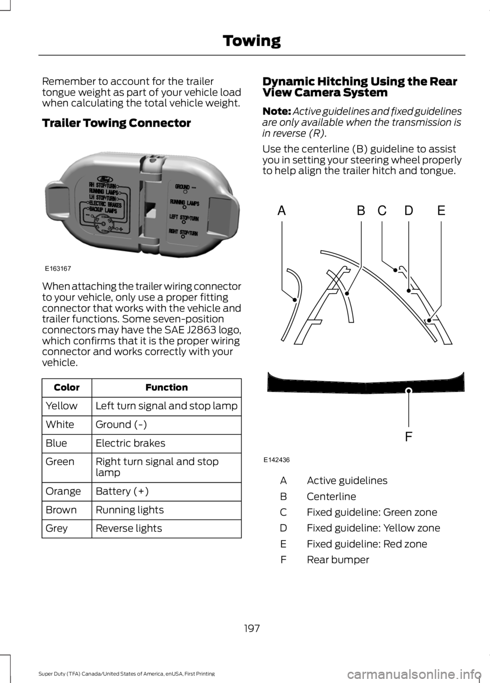
Grey Dynamic Hitching Using the Rear
View Camera System
Note:
Active guidelines and fixed guidelines
are only available when the transmission is
in reverse (R).
Use the centerline (B) guideline to assist
you in setting your steering wheel properly
to help align the trailer hitch and tongue. Active guidelines
A
Centerline
B
Fixed guideline: Green zone
C
Fixed guideline: Yellow zone
D
Fixed guideline: Red zone
E
Rear bumper
F
197
Super Duty (TFA) Canada/United States of America, enUSA, First Printing TowingE163167 ABCD
F
E
E142436
Page 201 of 507

Fixed guidelines are always shown in the
display, but the active guidelines only
display when the steering wheel is turned.
To use active guidelines, turn the steering
wheel to point the guidelines toward an
intended path. If the steering wheel
position is changed while reversing, your
vehicle might deviate from the original
intended path.
The active guidelines fade in and out
depending on the steering wheel position.
The active guidelines are not shown when
the steering wheel position is straight.
Always use caution while reversing.
Objects in the red zone are closest to your
vehicle and objects in the green zone are
farther away. Objects are getting closer to
your vehicle as they move from the green
zone to the yellow or red zones. Use the
side view mirrors and rear view mirror to
get better coverage on both sides and rear
of your vehicle.
Refer to the Rear View Camera section for
additional information. See Rear View
Camera (page 180).
Hitches WARNING
On pick-up trucks, the trailer hitch
provided on this vehicle enhances
crash protection for the fuel system.
Do not remove! Do not use a hitch that either clamps onto
the bumper or attaches to the axle. You
must distribute the load in your trailer so
that 10-15% for conventional towing or
15-25% for fifth wheel towing of the total
weight of the trailer is on the tongue. Weight-distributing Hitches WARNING
Do not adjust a weight-distributing
hitch to any position where the rear
bumper of the vehicle is higher than
it was before attaching the trailer. Doing
so will defeat the function of the
weight-distributing hitch, which may cause
unpredictable handling, and could result
in serious personal injury. When hooking-up a trailer using a
weight-distributing hitch, always use the
following procedure:
1. Park the loaded vehicle, without the
trailer, on a level surface.
2. Measure the height to the top of your vehicle's front wheel opening on the
fender. This is H1.
3. Attach the loaded trailer to your vehicle
without the weight-distributing bars
connected.
4. Measure the height to the top of your vehicle's front wheel opening on the
fender a second time. This is H2.
5. Install and adjust the tension in the weight-distributing bars so that the
height of your vehicle's front wheel
opening on the fender is approximately
halfway between H1 and H2.
6. Check that the trailer is level or slightly
nose down toward your vehicle. If not,
adjust the ball height accordingly and
repeat Steps 2-6.
Once the trailer is level or slightly nose
down toward the vehicle:
• Lock the bar tension adjuster in place.
• Check that the trailer tongue securely
attaches and locks onto the hitch.
• Install safety chains, lighting, and trailer
brake controls as required by law or the
trailer manufacturer.
198
Super Duty (TFA) Canada/United States of America, enUSA, First Printing Towing
Page 202 of 507

Fifth-wheel Trailer Hitch (If Equipped)
WARNINGS
The mounting pads in the bed are
specifically designed for certain
fifth-wheel trailer hitches and
gooseneck ball hitches. Do not use these
mounting pads for other purposes. Doing
so could result in vehicle structural
damage, loss of vehicle control, and
personal injury. Contact an authorized
dealer to purchase gooseneck and
fifth-wheel hitches that are compatible
with your vehicle. Towing trailers beyond the maximum
limit of the towing system could
result in vehicle structural damage,
loss of vehicle control and personal injury. The hitch rating listed on the trailer
hitch label is the maximum possible
trailer rating. To find the maximum
trailer weight allowed for your specific
vehicle, consult an authorized dealer or the
RV & Trailer Towing Guide provided by an
authorized dealer. Your vehicle may be equipped with a
fifth-wheel prep package. This package
enables your vehicle to accept certain
fifth-wheel trailer hitches and gooseneck
ball hitches. The fifth-wheel trailer hitch
attaches to the four mounting pads in the
pick-up bed. An optional 7-pin trailer wiring
connector may be in the bed as well. The
gooseneck ball hitch is a separate
mounting pad from the fifth-wheel hitch,
located in the center of the bed.
Shorter pick-up boxes, such as the 6½-foot
box on the F-250 and F-350, provide less
clearance between the cab and the
fifth-wheel and gooseneck trailer
compared to longer box pick-ups, such as
an 8-foot box on the F-250 or F-350. When
selecting a trailer and tow vehicle, it is
critical to check that this combination
provides clearance between the front of the trailer and tow vehicle for turns up to
90 degrees. Failure to follow this
recommendation could result in the trailer
contacting the cab of the tow vehicle
during tight turns that are typical during
low-speed parking and turning maneuvers.
This contact could result in damage to the
trailer and tow vehicle.
Safety Chains
Note:
Do not attach safety chains to the
bumper.
Always connect the safety chains to the
frame or hook retainers of your vehicle
hitch.
To connect the safety chains, cross the
chains under the trailer tongue and allow
enough slack for turning tight corners. Do
not allow the chains to drag on the ground.
Trailer Brakes WARNING
Do not connect a trailer's hydraulic
brake system directly to your
vehicle's brake system. Your vehicle
may not have enough braking power and
your chances of having a collision greatly
increase. Electric brakes and manual, automatic or
surge-type trailer brakes are safe if you
install them properly and adjust them to
the manufacturer's specifications. The
trailer brakes must meet local and federal
regulations.
The rating for the tow vehicle's braking
system operation is at the gross vehicle
weight rating, not the gross combined
weight rating.
Separate functioning brake systems
are required for safe control of towed
vehicles and trailers weighing more
than 1500 pounds (680 kilograms)
when loaded.
199
Super Duty (TFA) Canada/United States of America, enUSA, First Printing Towing