Page 40 of 154

PRINCIPLE OF OPERATION
Cruise control lets you maintain a setspeed without keeping your foot on theaccelerator pedal. You can use cruisecontrol when your vehicle speed is greaterthan 20 mph (30 km/h).
USING CRUISE CONTROL
WARNINGS
Do not use cruise control on windingroads, in heavy traffic or when theroad surface is slippery. This couldresult in loss of vehicle control, seriousinjury or death.
When you are going downhill, yourvehicle speed may increase abovethe set speed. The system will notapply the brakes. Change down a gear toassist the system in maintaining the setspeed. Failure to do so could result in lossof vehicle control, serious injury or death.
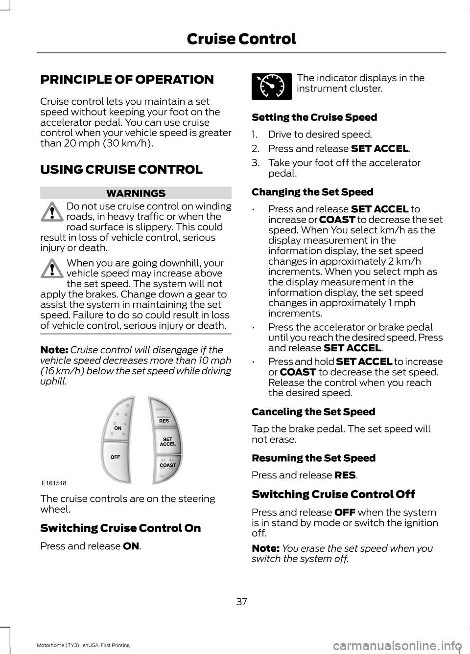
Note:Cruise control will disengage if thevehicle speed decreases more than 10 mph(16 km/h) below the set speed while drivinguphill.
The cruise controls are on the steeringwheel.
Switching Cruise Control On
Press and release ON.
The indicator displays in theinstrument cluster.
Setting the Cruise Speed
1.Drive to desired speed.
2.Press and release SET ACCEL.
3.Take your foot off the acceleratorpedal.
Changing the Set Speed
•Press and release SET ACCEL toincrease or COAST to decrease the setspeed. When You select km/h as thedisplay measurement in theinformation display, the set speedchanges in approximately 2 km/hincrements. When you select mph asthe display measurement in theinformation display, the set speedchanges in approximately 1 mphincrements.
•Press the accelerator or brake pedaluntil you reach the desired speed. Pressand release SET ACCEL.
•Press and hold SET ACCEL to increaseor COAST to decrease the set speed.Release the control when you reachthe desired speed.
Canceling the Set Speed
Tap the brake pedal. The set speed willnot erase.
Resuming the Set Speed
Press and release RES.
Switching Cruise Control Off
Press and release OFF when the systemis in stand by mode or switch the ignitionoff.
Note:You erase the set speed when youswitch the system off.
37Motorhome (TY3) , enUSA, First PrintingCruise ControlE161518 E71340
Page 57 of 154

Canadian roadside coverage and benefitsmay differ from the U.S. coverage. If yourequire more information, please refer tothe coverage section of your warrantyguide, call us in Canada at1-800-665-2006, or visit our website atwww.ford.ca.
Sykes Assistance Services Corporationadministers the Roadside Assistanceprogram. You must receive coveredservices in Canada or the continentalUnited States. Coverage extends tovehicles that use public, non-seasonal,annually traveled roadways. RoadsideAssistance coverage does not extend tovehicles involved in cross-country driving,logging, autocross and any other form ofoff-road use. Well maintained roads andsurfaces help ensure safe travel for thesupplier, and allow their representativesto perform service as per the standardoperating procedures.
In Remote Locations
If our supplier cannot take your vehicle byroad to the nearest authorized dealership,transportation by rail or water may benecessary. The program covers a tow tothe dock or rail terminal and also to thedealership at the end of the trip.
For rail or water transportation, however,contact your authorized dealer to confirmif you are eligible for additional coveragebefore you authorize or pay for the service.
Call Ford Roadside Assistance at1-800-665-2006 for additionalinformation.
HAZARD WARNING FLASHERS
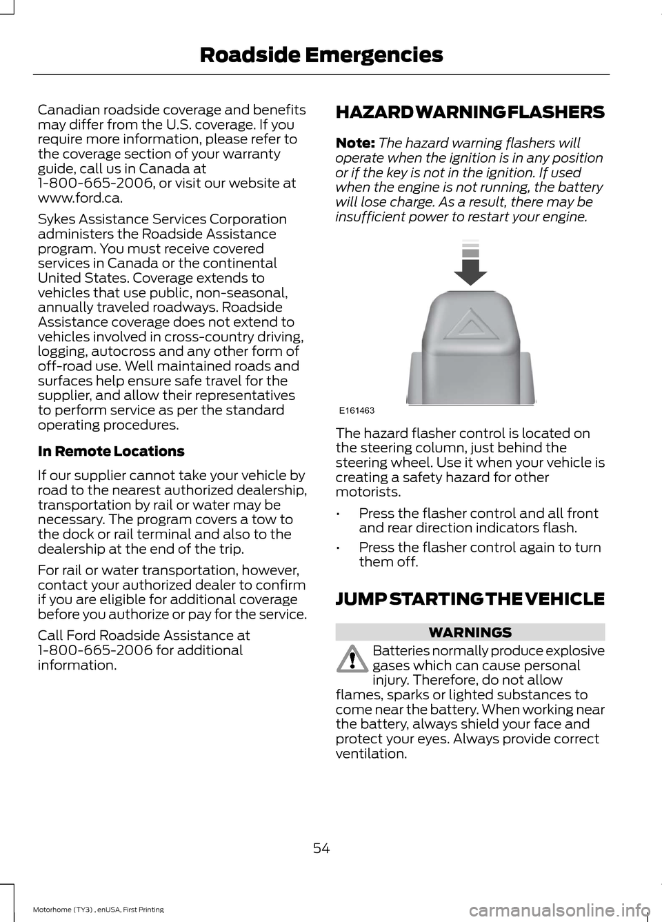
Note:The hazard warning flashers willoperate when the ignition is in any positionor if the key is not in the ignition. If usedwhen the engine is not running, the batterywill lose charge. As a result, there may beinsufficient power to restart your engine.
The hazard flasher control is located onthe steering column, just behind thesteering wheel. Use it when your vehicle iscreating a safety hazard for othermotorists.
•Press the flasher control and all frontand rear direction indicators flash.
•Press the flasher control again to turnthem off.
JUMP STARTING THE VEHICLE
WARNINGS
Batteries normally produce explosivegases which can cause personalinjury. Therefore, do not allowflames, sparks or lighted substances tocome near the battery. When working nearthe battery, always shield your face andprotect your eyes. Always provide correctventilation.
54Motorhome (TY3) , enUSA, First PrintingRoadside EmergenciesE161463
Page 67 of 154

Protected componentsFuse amp ratingFuse or relay number
Engine heated exhaust gas oxygen sensor#11 and #21.Vapor management valve.
Powertrain control module memory.5A*4Powertrain control module relay coil.
Powertrain control module power.20A*5
Instrument panel dimmer module.20A*6Park lamp feeds.Trailer tow running lamp relay coil.
Ignition coils.20A*7Radio capacitors.
Hydromax – Anti-lock brake systemmodule.30A*8
Powertrain control module.10A*9
Daytime running lamps.20A*10
Fuel pump relay coil.20A*11Powertrain control module power.Fuel pump diode.
Instrument panel - backup lamp feed.25A*12Trailer tow backup lamps feed.
Trailer tow electric brake controller feed.30A**13
Instrument panel battery feed (fuse #9, 15,21).60A**14
Lighting primary fuse.
Trailer tow park lamps.20A**15
Anti-lock brake system module –Hydromax.60A**16
Anti-lock brake system module – Hydro-boost.40A**
Horn feed.20A**17
Backup lamp relay coil.20A**18A/C clutch coil.A/C demand switch.
64Motorhome (TY3) , enUSA, First PrintingFuses
Page 68 of 154
Protected componentsFuse amp ratingFuse or relay number
Not used.—19
Powertrain control module relay coil.30A**20Powertrain control module relay (Powerdistribution box fuses # 3, 5, 7, 18).
Fuel injectors.20A**21Fuel pump motor.Mass air flow sensor.
Cigar lighter feed.20A**22Diagnostic tool connector.
Blower motor feed.40A**23
Instrument panel battery feed (fuses #4,10, 16, 22).50A**24
Ignition switch feed (Instrument panelfuses #1, 5, 7, 11, 13, 14, 17, 19, 23, 36; Powerdistribution box fuses #9, 11).
40A**25
Ignition switch feed (Instrument panelfuses #5, 11, 17, 23, 26, 38).40A**26
Multi-function switch (headlamps).30A**27
Starter relay feed.30A**28Starter motor.
Power brake assist motor – Hydromax.60A**29
Anti-lock brake system module – Hydro-boost.40A**
Air conditioning clutch relay.—R1
Fuel pump relay.—R2
Horn relay.—R3
Starter relay.—R4
Blower motor relay.—R5
Powertrain control module relay.—R6
65Motorhome (TY3) , enUSA, First PrintingFuses
Page 70 of 154
Protected componentsFuse amp ratingFuse or relay number
Not used.—F4
Running lamps.20A*F5Trailer tow lamp relay coil.
Not used.—F6
Reverse lamps.25A*F7Instrument panel fuses #33, 34.
Not used.—F8
Daytime running lamps.20A*F9
Not used.—F10
Not used.—F11
Not used.—F12
Not used.—F13
Not used.—F14
Hydromax pump motor.5A*F15
Vehicle power 1.20A*F16Powertrain control module power.
Vehicle power 2.20A*F17Catalyst monitor sensor.Engine heated exhaust gas oxygen sensor#11 and #21.Vapor management valve.
Vehicle power 4.20A*F18Ignition coils.
Powertrain control module.10A*F19
Hydromax module.10A*F20Brake on/off relay feed.
Powertrain control module.20A*F21Fuel pump diode.
Not used.—F22
Not used.—F23
Not used.—F24
67Motorhome (TY3) , enUSA, First PrintingFuses
Page 71 of 154

Protected componentsFuse amp ratingFuse or relay number
Blower motor relay feed.40A**J1
Headlamps.30A**J2Daytime running lamps on/off relay coil.Headlamp daytime running lamp relayfeed.Instrument panel fuses #25, 31.
Vehicle power.30A**J3Powertrain control module relay feed.Power distribution box fuse F16, F17, F18,J22.
Cigar lighter feed.20A**J4Diagnostic tool connector.
Not used.—J5
Starter relay feed.30A**J6Starter motor.
Anti-lock brake system.40A**J7Hydromax pump60A**
Trailer tow park lamps.20A**J8
Instrument panel fuse #4, 10, 16, 22.50A**J9
4-channel anti-lock brake system module.60A**J10
3-channel anti-lock brake system module.40A**
Fuel pump relay feed.20A**J11Fuel injectors.Mass air flow sensor.Fuel pump motor.
Trailer tow electronic brake.30A**J12
Ignition switch feed (instrument panelfuses #1, 5, 7, 11, 13, 17, 19, 23).40A**J13
Not used.—J14
Instrument panel fuses #9, 15, 21.60A**J15
Horn.20A**J16
Ignition switch feed (instrument panelfuses #1, 5, 7, 11, 13, 17, 19, 23.40A**J17
68Motorhome (TY3) , enUSA, First PrintingFuses
Page 74 of 154
UPS Power Distribution Box 2
Protected componentsFuse amp ratingFuse or relay number
Backup lamps.25A*M1
Daytime running lamps.20A*M2
4–channel anti-lock brake system module(Hydromax).30A*M3
Powertrain control module run/start.20A*M4Fuel pump relay coil.
Starter relay coil.10A*M5
Vehicle power 4.20A*M6Ignition coils.
Hydromax motor monitor.5A*M7
Vehicle power 2.20A*M8
Vehicle power 1.20A*M9Mass air flow sensor.
Air conditioning.10A*M10
Powertrain control module relay keep alivepower.5A*M11
Canister vent valve.
Parking lamps feed.20A*M12Trailer tow running lamp relay coil.
One-touch start.DiodeD1
71Motorhome (TY3) , enUSA, First PrintingFusesE172544
Page 75 of 154
Protected componentsFuse amp ratingFuse or relay number
Fuel pump.DiodeD2
Air conditioning.DiodeD3
Not used.—R2-1
Powertrain control module vehicle power.30A**J1
Fuel pump.20A**J2
Cigar lighter power point.20A**J3Diagnostic connector.
Blower motor.40A**J4
Headlamps.30A**J5Daytime running lamps on/off relay coil.Headlamp daytime running lamp relayfeed.
Ignition switch feeds (instrument panelfuses #F26).40A**J6
Ignition switch feeds (instrument panel#F21, F26).40A**J7
Instrument panel fuse box F11, F13, F15.50A**J8
Starter relay feed.30A**J9
4–channel anti-lock brake system module(Hydromax).60A**J10
Trailer tow electronic brake.30A**J11
Lighting (instrument panel fuses #F3, F5;power distribution box M1-2).60A**J12
Vehicle power 3.20A**J13
Horn.20A**J14
4–channel anti-lock brake system module.60A**J15
Trailer tow parking lamps.20A**J16
*Mini fuse.**J-case fuse.
72Motorhome (TY3) , enUSA, First PrintingFuses