Page 259 of 421

Vertical Aim Adjustment
1. Park your vehicle directly in front of a
wall or screen on a level surface,
approximately 25 feet (7.6 meters)
away.
2. Measure the height from the center of your headlamp (indicated by a 3.0
millimeter circle on the lens) to the
ground and mark an 8 foot (2.4 meter)
horizontal reference line on the vertical
wall or screen at this height (a piece of
masking tape works well).
Note: To see a clearer light pattern for
adjusting, you may want to block the light
from one headlamp while adjusting the
other.
3. Switch on the low beam headlamps to
illuminate the wall or screen and open
the hood. Cover one of the headlamps
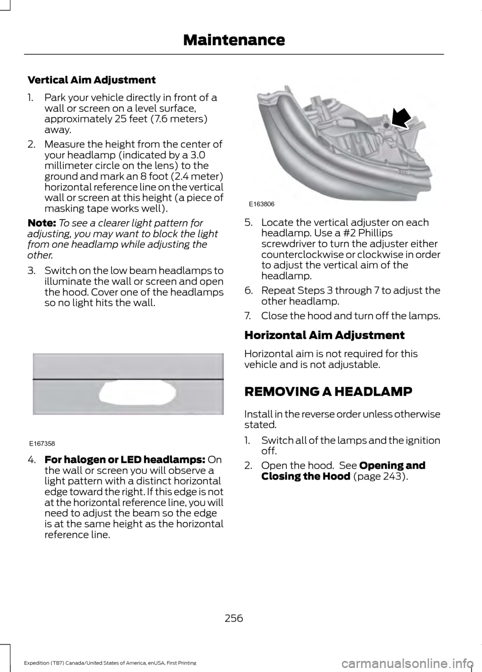
so no light hits the wall. 4.
For halogen or LED headlamps: On
the wall or screen you will observe a
light pattern with a distinct horizontal
edge toward the right. If this edge is not
at the horizontal reference line, you will
need to adjust the beam so the edge
is at the same height as the horizontal
reference line. 5. Locate the vertical adjuster on each
headlamp. Use a #2 Phillips
screwdriver to turn the adjuster either
counterclockwise or clockwise in order
to adjust the vertical aim of the
headlamp.
6. Repeat Steps 3 through 7 to adjust the
other headlamp.
7. Close the hood and turn off the lamps.
Horizontal Aim Adjustment
Horizontal aim is not required for this
vehicle and is not adjustable.
REMOVING A HEADLAMP
Install in the reverse order unless otherwise
stated.
1. Switch all of the lamps and the ignition
off.
2. Open the hood. See Opening and
Closing the Hood (page 243).
256
Expedition (TB7) Canada/United States of America, enUSA, First Printing MaintenanceE167358 E163806
Page 260 of 421

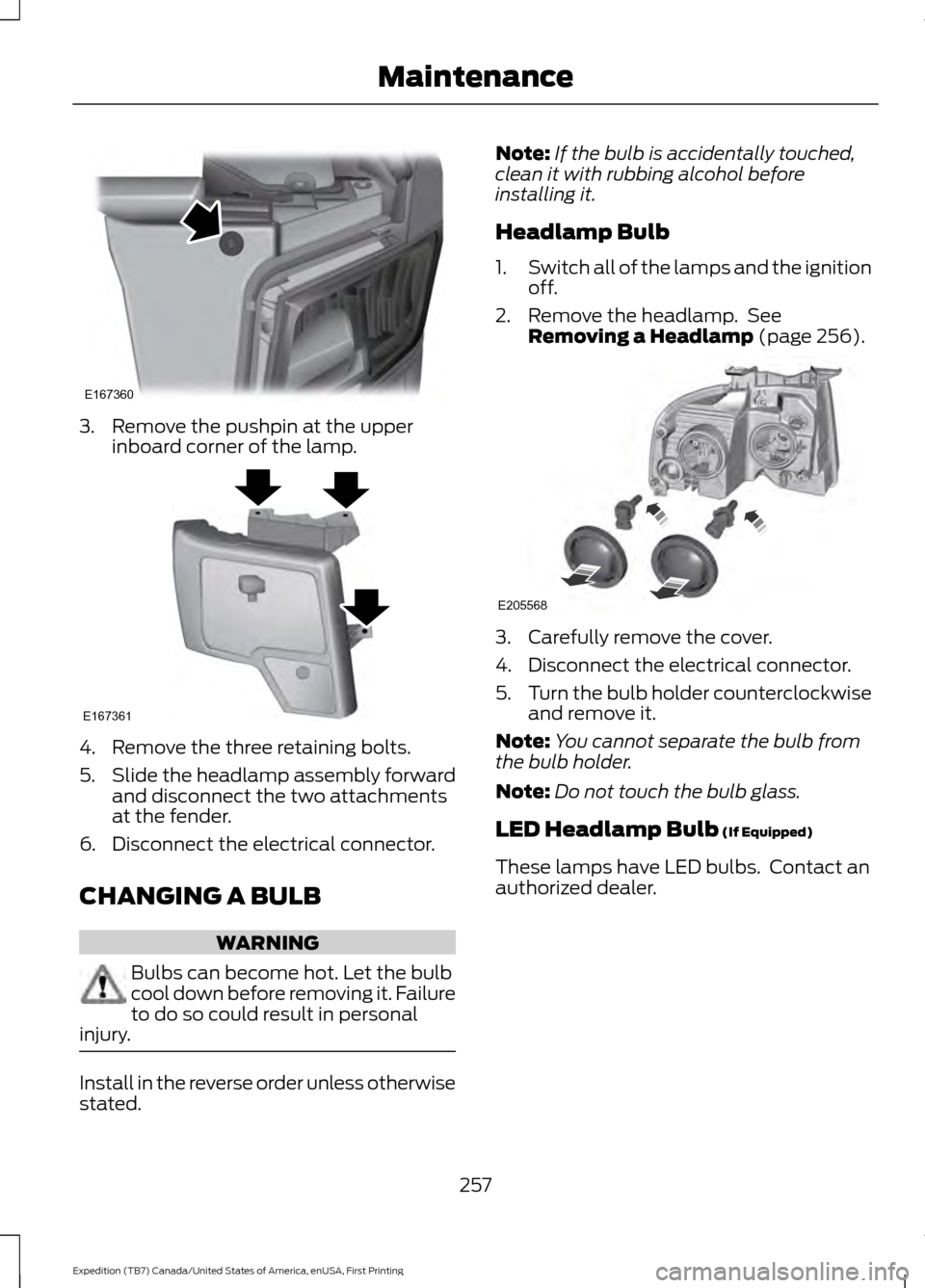
3. Remove the pushpin at the upper
inboard corner of the lamp. 4. Remove the three retaining bolts.
5.
Slide the headlamp assembly forward
and disconnect the two attachments
at the fender.
6. Disconnect the electrical connector.
CHANGING A BULB WARNING
Bulbs can become hot. Let the bulb
cool down before removing it. Failure
to do so could result in personal
injury. Install in the reverse order unless otherwise
stated. Note:
If the bulb is accidentally touched,
clean it with rubbing alcohol before
installing it.
Headlamp Bulb
1. Switch all of the lamps and the ignition
off.
2. Remove the headlamp. See Removing a Headlamp (page 256). 3. Carefully remove the cover.
4. Disconnect the electrical connector.
5.
Turn the bulb holder counterclockwise
and remove it.
Note: You cannot separate the bulb from
the bulb holder.
Note: Do not touch the bulb glass.
LED Headlamp Bulb
(If Equipped)
These lamps have LED bulbs. Contact an
authorized dealer.
257
Expedition (TB7) Canada/United States of America, enUSA, First Printing MaintenanceE167360 E167361 E205568
Page 261 of 421
Front Direction Indicator Bulb
1.
Switch all of the lamps and the ignition
off.
2. Remove the headlamp. See Removing a Headlamp (page 256).
3. Turn the bulb holder counterclockwise
and remove it.
4. Remove the bulb by pulling it straight out.
Side Marker Bulb 1.
Switch all of the lamps and the ignition
off.
2. Turn the bulb holder counterclockwise
and remove it.
Note: You cannot separate the bulb from
the bulb holder.
Note: Do not touch the bulb glass. LED Direction Indicator and Side
Marker Bulbs
(If Equipped)
These lamps have LED bulbs. Contact an
authorized dealer.
Fog Lamp Bulb
(If Equipped) 1.
Switch all of the lamps and the ignition
off.
2. Disconnect the electrical connector.
3. Turn the bulb holder counterclockwise
and remove it.
Note: You cannot separate the bulb from
the bulb holder.
Note: Do not touch the bulb glass.
258
Expedition (TB7) Canada/United States of America, enUSA, First Printing MaintenanceE205569 E183764 E163826
Page 262 of 421

Rear Lamp, Brake Lamp, Rear
Direction Indicator and Reverse
Lamp Bulbs
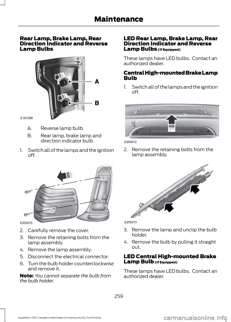
Reverse lamp bulb.
A.
Rear lamp, brake lamp and
direction indicator bulb.
B.
1. Switch all of the lamps and the ignition
off. 2. Carefully remove the cover.
3. Remove the retaining bolts from the
lamp assembly.
4. Remove the lamp assembly.
5. Disconnect the electrical connector.
6. Turn the bulb holder counterclockwise
and remove it.
Note: You cannot separate the bulb from
the bulb holder. LED Rear Lamp, Brake Lamp, Rear
Direction Indicator and Reverse
Lamp Bulbs (If Equipped)
These lamps have LED bulbs. Contact an
authorized dealer.
Central High-mounted Brake Lamp
Bulb
1. Switch all of the lamps and the ignition
off. 2. Remove the retaining bolts from the
lamp assembly. 3. Remove the lamp and unclip the bulb
holder.
4. Remove the bulb by pulling it straight out.
LED Central High-mounted Brake
Lamp Bulb
(If Equipped)
These lamps have LED bulbs. Contact an
authorized dealer.
259
Expedition (TB7) Canada/United States of America, enUSA, First Printing MaintenanceE187289 E205570 E205572 E205573
Page 263 of 421

License Plate Lamp Bulb
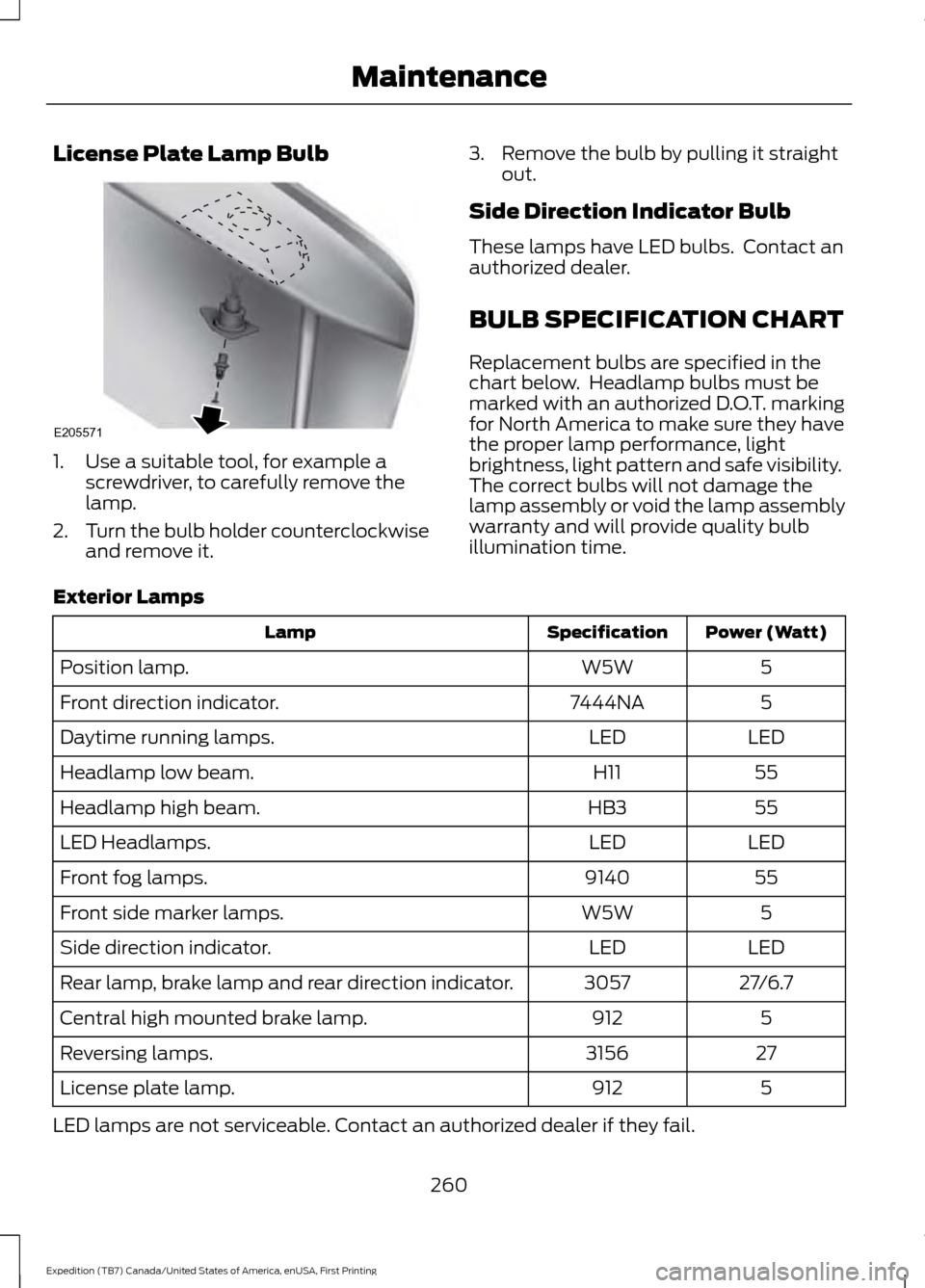
1. Use a suitable tool, for example a
screwdriver, to carefully remove the
lamp.
2. Turn the bulb holder counterclockwise
and remove it. 3. Remove the bulb by pulling it straight
out.
Side Direction Indicator Bulb
These lamps have LED bulbs. Contact an
authorized dealer.
BULB SPECIFICATION CHART
Replacement bulbs are specified in the
chart below. Headlamp bulbs must be
marked with an authorized D.O.T. marking
for North America to make sure they have
the proper lamp performance, light
brightness, light pattern and safe visibility.
The correct bulbs will not damage the
lamp assembly or void the lamp assembly
warranty and will provide quality bulb
illumination time.
Exterior Lamps Power (Watt)
Specification
Lamp
5
W5W
Position lamp.
5
7444NA
Front direction indicator.
LED
LED
Daytime running lamps.
55
H11
Headlamp low beam.
55
HB3
Headlamp high beam.
LED
LED
LED Headlamps.
55
9140
Front fog lamps.
5
W5W
Front side marker lamps.
LED
LED
Side direction indicator.
27/6.7
3057
Rear lamp, brake lamp and rear direction indicator.
5
912
Central high mounted brake lamp.
27
3156
Reversing lamps.
5
912
License plate lamp.
LED lamps are not serviceable. Contact an authorized dealer if they fail.
260
Expedition (TB7) Canada/United States of America, enUSA, First Printing MaintenanceE205571
Page 264 of 421
Interior Lamps
Power (Watt)
Specification
Lamp
3.5
194
Glove compartment lamp.
A6224PF
Vanity mirror lamp.
5
W5W
Map lamp.
5
W5W
Interior lamp. 1
10
578
Rear dome lamp.
1 Second row rail lamp.
261
Expedition (TB7) Canada/United States of America, enUSA, First Printing Maintenance
Page 265 of 421

CHANGING THE ENGINE AIR
FILTER
WARNING
To reduce the risk of vehicle damage
and personal burn injuries, do not
start your engine with the air cleaner
removed and do not remove it while the
engine is running. Note:
Failure to use the correct air filter
element may result in severe engine
damage. Resulting component damage
may not be covered by the vehicle Warranty.
When changing the air filter element, use
only the air filter element listed. See
Motorcraft Parts (page 303).
Change the air filter element at the correct
interval. See
Scheduled Maintenance
(page 372). 1. Locate the mass air flow sensor
electrical connector on the air outlet
tube. Disconnect the mass air flow
sensor electrical connector. 2. Reposition the locking clip on the
connector (connector shown from
below for clarity), squeeze the
connector and pull it off of the air
outlet tube. 3.
Clean the area from around the air tube
to the air cover connection to prevent
debris from entering the system. Next,
loosen the bolt on the air tube clamp
so the clamp is no longer snug to the
air tube. It is not necessary to
completely remove the clamp.
4. Pull the air tube off from the air cleaner
housing.
262
Expedition (TB7) Canada/United States of America, enUSA, First Printing MaintenanceE163755 E163756 E163757
Page 266 of 421
5. Release the three clamps that secure
the cover to the air filter housing. Push
the air filter cover toward the center of
the vehicle and up slightly to release it.
6. Remove the air filter element from the
air filter housing.
7. Install the new air filter element. 8.
Replace the air filter housing cover and
secure all the clamps. Be careful not
to crimp the filter element edges
between the air filter housing and cover
and ensure that you properly align the
tabs on the edge into the slots.
9. Slip the air tube onto the air filter housing and tighten the air-tube clamp
bolt snugly. Do not over tighten
air-tube clamp bolt. 10. Reconnect the mass air flow sensor
electrical connector to the outlet
tube. Make sure the locking tab on
the connector is in the locked position
(connector shown from below for
clarity).
263
Expedition (TB7) Canada/United States of America, enUSA, First Printing MaintenanceE163758 E163759 E163760