2016 FIAT TIPO 5DOORS STATION WAGON AUX
[x] Cancel search: AUXPage 10 of 240

INSTRUMENT PANEL
Version with Uconnect™3" Radio, Uconnect™5" LIVE and Uconnect™5" Nav
LIVE
1. Adjustable side air diffusers 2. Left stalk: direction indicators, main beam headlights, flashings 3. Instrument panel
4. Steering wheel controls 5. Right stalk: windscreen wiper/washer, rear window wiper/washer, rain sensor sensitivity level
setting 6.Uconnect™7. Control buttons 8. Passenger front airbag 9. Adjustable central air diffusers 10. Glove
compartment 11. Climate controls 12. Buttons on the central console: seat heating, USB port + AUX plug panel,
socket/cigarette lighter 13. Ignition device 14. Driver front airbag 15. Steering wheel controls 16. Control panel: front fog
lights (where present), rear fog lights, headlight alignment adjustment, iTPMS reset, ESC OFF (where present).
1P2000085-000-000
8
KNOWING YOUR CAR
Page 11 of 240

Version with Uconnect™7" HD LIVE and Uconnect™7" HD Nav LIVE
1. Adjustable side air diffusers 2. Left stalk: direction indicators, main beam headlights, flashings 3. Instrument panel
4. Steering wheel controls 5. Right stalk: windscreen wiper/washer, rear window wiper/washer, rain sensor sensitivity level
setting 6.Uconnect™7. Control buttons 8. Passenger front airbag 9. Adjustable central air diffusers 10. Glove
compartment 11. Climate controls 12. Buttons on the central console: seat heating, USB port + AUX plug panel,
socket/cigarette lighter 13. Ignition device 14. Driver front airbag 15. Steering wheel controls 16. Control panel: front fog
lights (where present), rear fog lights, headlight alignment adjustment, iTPMS reset, ESC OFF (where present).
2P2000050-000-000
9
Page 42 of 240

to reset the displayed/selected
functions.
MAIN MENU
The Main menu comprises a series of
items which can be selected using the
control buttons to access the different
selection and setting options given in
the following paragraphs.
REMARKS
Some options have a submenu.
With theUconnect™ 5"or7" HD
system, some Menu items are shown
and managed on the display of the
latter and not on the instrument panel
display (refer to the dedicated
Multimedia chapter or to the
supplement available online).
MENU OPTIONS
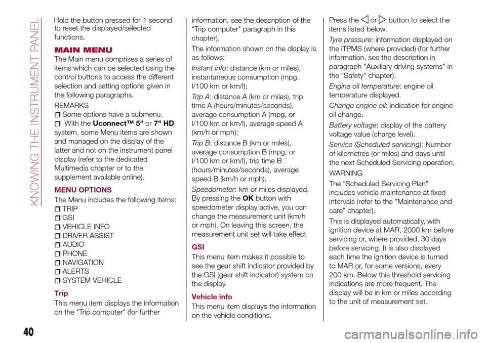
The Menu includes the following items:
TRIP
GSI
VEHICLE INFO
DRIVER ASSIST
AUDIO
PHONE
NAVIGATION
ALERTS
SYSTEM VEHICLE
Trip
This menu item displays the information
on the "Trip computer" (for furtherinformation, see the description of the
"Trip computer" paragraph in this
chapter).
The information shown on the display is
as follows:
Instant info: distance (km or miles),
instantaneous consumption (mpg,
l/100 km or km/l);
Trip A: distance A (km or miles), trip
time A (hours/minutes/seconds),
average consumption A (mpg, or
l/100 km or km/l), average speed A
(km/h or mph);
Trip B: distance B (km or miles),
average consumption B (mpg, or
l/100 km or km/l), trip time B
(hours/minutes/seconds), average
speed B (km/h or mph).
Speedometer: km or miles displayed.
By pressing theOKbutton with
speedometer display active, you can
change the measurement unit (km/h
or mph). On leaving this screen, the
measurement unit set will take effect.
GSI
This menu item makes it possible to
see the gear shift indicator provided by
the GSI (gear shift indicator) system on
the display.
Vehicle info
This menu item displays the information
on the vehicle conditions.Press the
orbutton to select the
items listed below.
Tyre pressure: information displayed on
the iTPMS (where provided) (for further
information, see the description in
paragraph "Auxiliary driving systems" in
the "Safety" chapter).
Engine oil temperature: engine oil
temperature displayed.
Change engine oil: indication for engine
oil change.
Battery voltage: display of the battery
voltage value (charge level).
Service (Scheduled servicing):Number
of kilometres (or miles) and days until
the next Scheduled Servicing operation.
WARNING
The “Scheduled Servicing Plan”
includes vehicle maintenance at fixed
intervals (refer to the "Maintenance and
care" chapter).
This is displayed automatically, with
ignition device at MAR, 2000 km before
servicing or, where provided, 30 days
before servicing. It is also displayed
each time the ignition device is turned
to MAR or, for some versions, every
200 km. Below this threshold servicing
indications are more frequent. The
display will be in km or miles according
to the unit of measurement set.
40
KNOWING THE INSTRUMENT PANEL
Hold the button pressed for 1 second
Page 69 of 240

59)If the driver depresses the brake pedal
fully or carries out a fast steering during
system operation, the automatic braking
function may stop (e.g. to allow a possible
manoeuvre to avoid the obstacle).
60)The system intervenes on vehicles
travelling in the same lane. People, animals
and things (e.g. pushchairs) are not taken
into consideration.
61)If the car must be placed on a roller
bench for maintenance interventions or if it
is washed in an automatic roller washing
tunnel with an obstacle in the front part
(e.g. another car, a wall or another
obstacle), the system may detect its
presence and activate. In this case the
system must be deactivated through the
settings of theUconnect™5"or7" HD
system.
62)If the iTMPS system signals a pressure
decrease on the tyres, it is recommended
to check the pressure on all four tyres.
63)The iTPMS does not relieve the driver
from the obligation to check the tyre
pressure every month; it is not even to be
considered a replacing system for
maintenance or a safety system.
64)Tyre pressure must be checked with
tyres cold. Should it become necessary for
whatever reason to check pressure with
warm tyres, do not reduce pressure even
though it is higher than the prescribed
value, but repeat the check when tyres are
cold
65)The iTPMS cannot indicate sudden tyre
pressure drops (e.g. if a tyre bursts). In this
case, stop the vehicle, braking with caution
and avoiding abrupt steering.
66)The system only warns that the tyre
pressure is low: it is not able to inflate
them.67)Insufficient tyre inflation increases fuel
consumption, reduces the tread duration
and may affect the capacity to drive safely.
IMPORTANT
18)The system may have limited or absent
operation due to weather conditions such
as: heavy rain, hail, thick fog, heavy snow.
19)The section of the bumper before the
sensor must not be covered with
adhesives, auxiliary headlights or any other
object.
20)System intervention might be
unexpected or delayed when other vehicles
transport loads projecting from the side,
above or from the rear, with respect to the
normal size of the vehicle.
21)Operation can be adversely affected by
any structural change made to the vehicle,
such as a modification to the front
geometry, tyre change, or a heavier load
than the standard load of the vehicle.
22)Incorrect repairs made on the front part
of the vehicle (e.g. bumper, chassis) may
alter the position of the radar sensor, and
adversely affect its operation. Go to a Fiat
Dealership for any operation of this type.
23)Do not tamper nor operate on the radar
sensor. In the event of a sensor failure,
contact a Fiat Dealership.
24)When towing a trailer (with modules
installed after purchasing the vehicle), a
vehicle or during loading manoeuvres on a
vehicle transporter (or in vehicle for
transport), the system must be deactivated
via theUconnect™5"or7" HDsystem.25)Do not wash with high-pressure jets in
the bumper lower area: in particular do not
operate on the system's electrical
connector.
26)Be careful in the case of repairs and
new paintings in the area around the
sensor (panel covering the sensor on the
left side of the bumper). In the event of a
frontal impact the sensor may automatically
deactivate and display a warning to indicate
that the sensor needs to be repaired. Even
without a malfunction warning, deactivate
the system operation if you think that the
position of the radar sensor has changed
(e.g. due to low-speed frontal impact as
during parking manoeuvres). In these
cases, go to a Fiat Dealership to have the
radar sensor realigned or replaced.
67
Page 109 of 240

ELECTRONIC CRUISE
CONTROL MODE
Electronic Cruise Control mode is
available for travelling at constant speed
in addition to the Adaptive Cruise
Control (ACC) mode.
If the Adaptive Cruise Control (ACC)
function is implemented on the vehicle,
the electronic Cruise Control works in
the same manner as the ACC (by
pressing the
button of the Cruise
Control) with the difference that:
it does not hold the distance from the
vehicle ahead;
the device keeps working if the
radar sensor is obstructed.
Before returning to the previously set
speed, bring the speed close to that
value, press the RES (Resume) button
and then release it.
WARNING
114)Pay the utmost attention while driving
at all times and be always ready to press
the brakes if needed.
115)The system is an aid for the driver,
who must always pay full attention while
driving. The responsibility always rests with
the driver, who must take into account the
traffic conditions in order to drive in
complete safety. The driver must always
maintain a safe distance from the vehicle in
front.
116)The device is not activated in
presence of pedestrians, oncoming
vehicles in the opposite direction of travel
or moving in the crosswise direction and
stationary objects (e.g. a vehicle standing
in a queue or a broken down vehicle).
117)The device cannot take account of
road, traffic and weather conditions, and
conditions of poor visibility (e.g. fog).
118)The device cannot take account of
road, traffic and weather conditions, and
conditions of poor visibility (e.g. fog).
119)The device cannot apply the
maximum braking force: the car will not be
stopped completely.
IMPORTANT
34)The system may have limited or absent
operation due to weather conditions such
as: heavy rain, hail, thick fog, heavy snow.35)The section of the bumper before the
sensor must not be covered with
adhesives, auxiliary headlights or any other
object.
36)Operation can be adversely affected by
any structural change made to the vehicle,
such as a modification to the front
geometry, tyre change, or a heavier load
than the standard load of the vehicle.
37)Incorrect repairs made on the front part
of the vehicle (e.g. bumper, chassis) may
alter the position of the radar sensor, and
adversely affect its operation. Go to a Fiat
Dealership for any operation of this type.
38)Do not tamper nor operate on the radar
sensor. In the event of a sensor failure,
contact a Fiat Dealership.
39)Do not wash with high-pressure jets in
the bumper lower area: in particular do not
operate on the system's electrical
connector.
40)Be careful in the case of repairs and
new paintings in the area around the
sensor (panel covering the sensor on the
left side of the bumper). In the event of a
frontal impact the sensor may automatically
deactivate and display a warning to indicate
that the sensor needs to be repaired. Even
without a malfunction warning, deactivate
the system operation if you think that the
position of the radar sensor has changed
(e.g. due to low-speed frontal impact as
during parking manoeuvres). In these
cases, go to a Fiat Dealership to have the
radar sensor realigned or replaced.
94P2000046-000-000
107
Page 115 of 240

to each country you are driving in, in the
case of vehicles towing trailers. In any
case, the top speed must not exceed
100 km/h.
Any electric brake must be powered
directly by the battery through a cable
with a cross-section of no less than 2.5
mm
2.
In addition to the electrical branches,
the vehicle electrical system can only be
connected to the supply cable for an
electric brake and to the cable for an
internal light for the trailer, not
exceeding 15 W. For connections, use
the preset control unit with a battery
cable with section not less than 2.5 mm
2.
IMPORTANT The use of auxiliary loads
other than external lights (e.g. electric
brake) must take place with engine
running.
INSTALLING A TOW
HOOK
To install a tow hook contact a Fiat
Dealership.
WARNING
122)The ABS with which the car is
equipped will not control the braking
system of the trailer. Particular caution is
required on slippery roads.123)Never modify the braking system of
the vehicle to control the trailer brake. The
trailer braking system must be fully
independent of the car’s hydraulic system.
REFUELLING THE
VEHICLE
124) 125) 126)
Before refuelling, make sure that the
fuel type is correct.
Also stop the engine before refuelling.
PETROL ENGINES
Only use unleaded petrol with a number
of octanes (R.O.N.) not lower than 95
(EN228 specification).
DIESEL ENGINES
45)
Only use Diesel for motor vehicles
(EN590 specification).
When using or parking the vehicle for a
long time in the mountains or cold
areas, it is advisable to refuel using
locally available Diesel. In this case, it is
also advisable to keep the tank over
50% full.
REFUELLING CAPACITY
To ensure that you fill the tank
completely, top up twice after the first
click of the fuel supply gun.
Further top-ups could cause faults in
the fuel feeding system.
113
Page 133 of 240

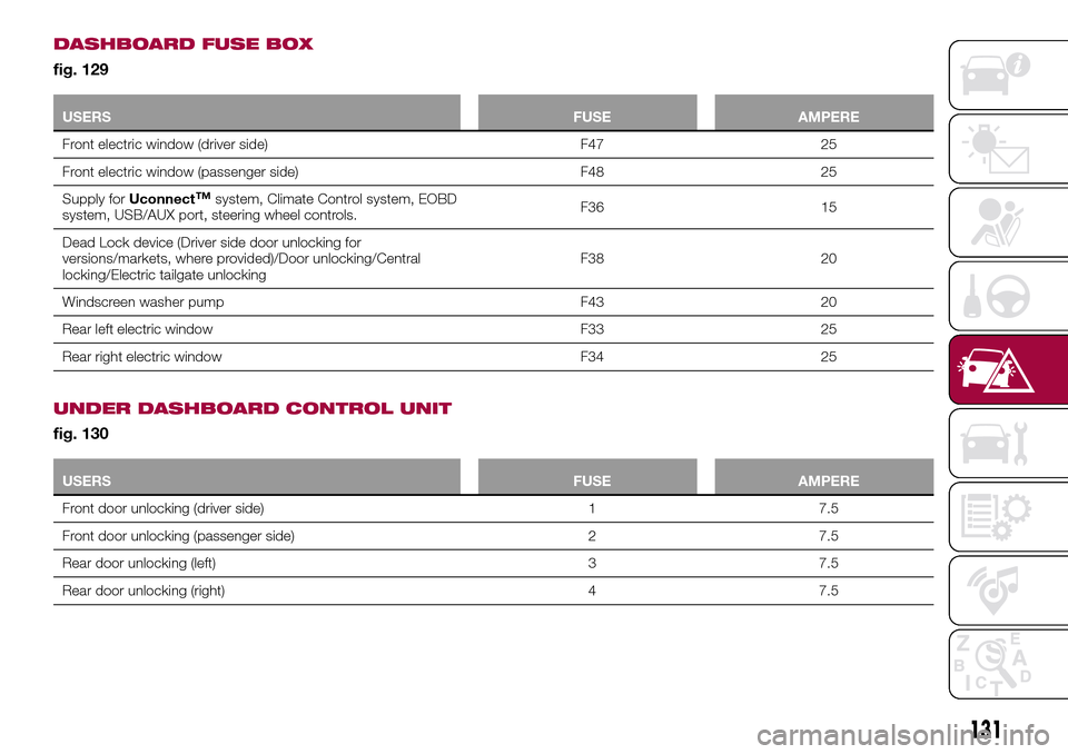
DASHBOARD FUSE BOX
fig. 129
USERSFUSE AMPERE
Front electric window (driver side) F47 25
Front electric window (passenger side) F48 25
Supply forUconnect
™system, Climate Control system, EOBD
system, USB/AUX port, steering wheel controls.F36 15
Dead Lock device (Driver side door unlocking for
versions/markets, where provided)/Door unlocking/Central
locking/Electric tailgate unlockingF38 20
Windscreen washer pump F43 20
Rear left electric window F33 25
Rear right electric window F34 25
UNDER DASHBOARD CONTROL UNIT
fig. 130
USERSFUSE AMPERE
Front door unlocking (driver side) 1 7.5
Front door unlocking (passenger side) 2 7.5
Rear door unlocking (left) 3 7.5
Rear door unlocking (right) 4 7.5
131
Page 141 of 240

JUMP STARTING
141) 142) 143) 144)
53)
If the battery is flat, a jump starting can
be performed using the battery and the
cables of another vehicle, or using an
auxiliary battery. In all cases, the battery
used must have a capacity equal to or
a little higher than the flat one.
Jump starting may be dangerous if
carried out incorrectly: carefully follow
the procedures described below.
JUMP STARTING
IMPORTANT NOTES
Do not use an auxiliary battery or any
other source of external supply with a
voltage above 12 V: the battery, the
starter, the alternator and the electrical
system of the vehicle could be
damaged.
Do not attempt jump starting if the
battery is frozen. The battery could
break and explode!
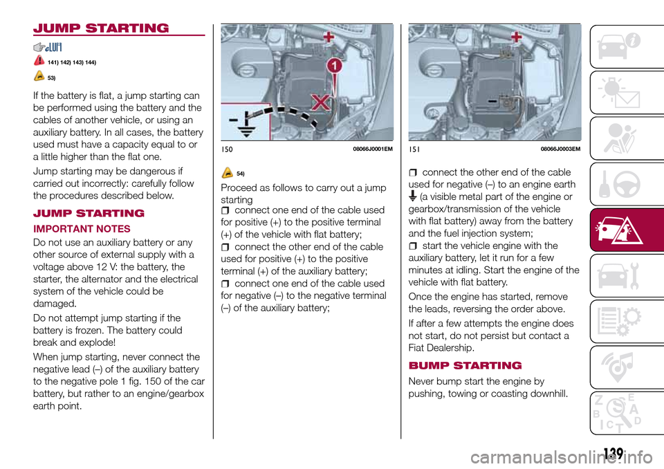
When jump starting, never connect the
negative lead (–) of the auxiliary battery
to the negative pole 1 fig. 150 of the car
battery, but rather to an engine/gearbox
earth point.
54)
Proceed as follows to carry out a jump
starting
connect one end of the cable used
for positive (+) to the positive terminal
(+) of the vehicle with flat battery;
connect the other end of the cable
used for positive (+) to the positive
terminal (+) of the auxiliary battery;
connect one end of the cable used
for negative (–) to the negative terminal
(–) of the auxiliary battery;
connect the other end of the cable
used for negative (–) to an engine earth
(a visible metal part of the engine or
gearbox/transmission of the vehicle
with flat battery) away from the battery
and the fuel injection system;
start the vehicle engine with the
auxiliary battery, let it run for a few
minutes at idling. Start the engine of the
vehicle with flat battery.
Once the engine has started, remove
the leads, reversing the order above.
If after a few attempts the engine does
not start, do not persist but contact a
Fiat Dealership.
BUMP STARTING
Never bump start the engine by
pushing, towing or coasting downhill.
15008066J0001EM15108066J0003EM
139