2016 FIAT TIPO 5DOORS STATION WAGON lights
[x] Cancel search: lightsPage 122 of 240
REPLACING AN
EXTERNAL BULB
Versions with polyelliptical
headlights
Front bulb position
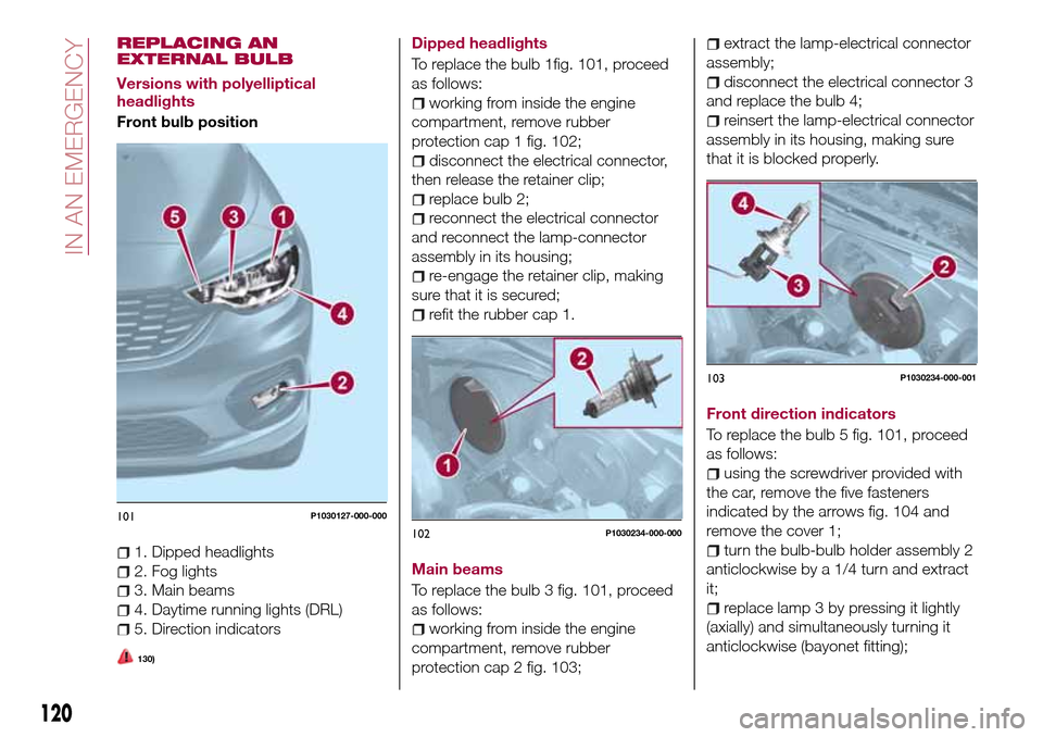
1. Dipped headlights
2. Fog lights
3. Main beams
4. Daytime running lights (DRL)
5. Direction indicators
130)
Dipped headlights
To replace the bulb 1fig. 101, proceed
as follows:
working from inside the engine
compartment, remove rubber
protection cap 1 fig. 102;
disconnect the electrical connector,
then release the retainer clip;
replace bulb 2;
reconnect the electrical connector
and reconnect the lamp-connector
assembly in its housing;
re-engage the retainer clip, making
sure that it is secured;
refit the rubber cap 1.
Main beams
To replace the bulb 3 fig. 101, proceed
as follows:
working from inside the engine
compartment, remove rubber
protection cap 2 fig. 103;
extract the lamp-electrical connector
assembly;
disconnect the electrical connector 3
and replace the bulb 4;
reinsert the lamp-electrical connector
assembly in its housing, making sure
that it is blocked properly.
Front direction indicators
To replace the bulb 5 fig. 101, proceed
as follows:
using the screwdriver provided with
the car, remove the five fasteners
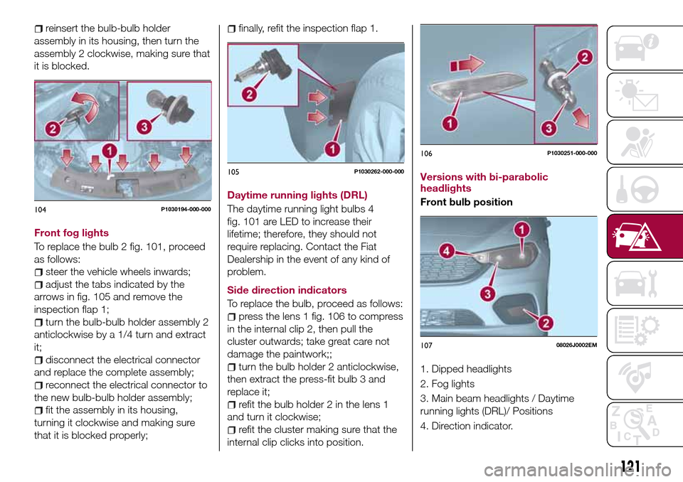
indicated by the arrows fig. 104 and
remove the cover 1;
turn the bulb-bulb holder assembly 2
anticlockwise by a 1/4 turn and extract
it;
replace lamp 3 by pressing it lightly
(axially) and simultaneously turning it
anticlockwise (bayonet fitting);
101P1030127-000-000
102P1030234-000-000
103P1030234-000-001
120
IN AN EMERGENCY
Page 123 of 240
reinsert the bulb-bulb holder
assembly in its housing, then turn the
assembly 2 clockwise, making sure that
it is blocked.
Front fog lights
To replace the bulb 2 fig. 101, proceed
as follows:
steer the vehicle wheels inwards;
adjust the tabs indicated by the
arrows in fig. 105 and remove the
inspection flap 1;
turn the bulb-bulb holder assembly 2
anticlockwise by a 1/4 turn and extract
it;
disconnect the electrical connector
and replace the complete assembly;
reconnect the electrical connector to
the new bulb-bulb holder assembly;
fit the assembly in its housing,
turning it clockwise and making sure
that it is blocked properly;
finally, refit the inspection flap 1.
Daytime running lights (DRL)
The daytime running light bulbs 4
fig. 101 are LED to increase their
lifetime; therefore, they should not
require replacing. Contact the Fiat
Dealership in the event of any kind of
problem.
Side direction indicators
To replace the bulb, proceed as follows:
press the lens 1 fig. 106 to compress
in the internal clip 2, then pull the
cluster outwards; take great care not
damage the paintwork;;
turn the bulb holder 2 anticlockwise,
then extract the press-fit bulb 3 and
replace it;
refit the bulb holder 2 in the lens 1
and turn it clockwise;
refit the cluster making sure that the
internal clip clicks into position.Versions with bi-parabolic
headlights
Front bulb position
1. Dipped headlights
2. Fog lights
3. Main beam headlights / Daytime
running lights (DRL)/ Positions
4. Direction indicator.
104P1030194-000-000
105P1030262-000-000
106P1030251-000-000
10708026J0002EM
121
Page 124 of 240
Main beam headlights / Daytime
running lights (DRL)/ Positions
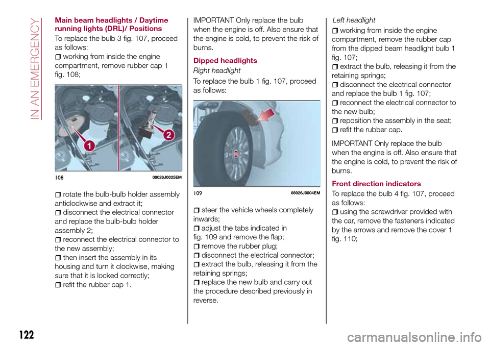
To replace the bulb 3 fig. 107, proceed
as follows:
working from inside the engine
compartment, remove rubber cap 1
fig. 108;
rotate the bulb-bulb holder assembly
anticlockwise and extract it;
disconnect the electrical connector
and replace the bulb-bulb holder
assembly 2;
reconnect the electrical connector to
the new assembly;
then insert the assembly in its
housing and turn it clockwise, making
sure that it is locked correctly;
refit the rubber cap 1.
IMPORTANT Only replace the bulb
when the engine is off. Also ensure that
the engine is cold, to prevent the risk of
burns.
Dipped headlights
Right headlight
To replace the bulb 1 fig. 107, proceed
as follows:
steer the vehicle wheels completely
inwards;
adjust the tabs indicated in
fig. 109 and remove the flap;
remove the rubber plug;
disconnect the electrical connector;
extract the bulb, releasing it from the
retaining springs;
replace the new bulb and carry out
the procedure described previously in
reverse.
working from inside the engine
compartment, remove the rubber cap
from the dipped beam headlight bulb 1
fig. 107;
extract the bulb, releasing it from the
retaining springs;
disconnect the electrical connector
and replace the bulb 1 fig. 107;
reconnect the electrical connector to
the new bulb;
reposition the assembly in the seat;
refit the rubber cap.
IMPORTANT Only replace the bulb
when the engine is off. Also ensure that
the engine is cold, to prevent the risk of
burns.
Front direction indicators
To replace the bulb 4 fig. 107, proceed
as follows:
using the screwdriver provided with
the car, remove the fasteners indicated
by the arrows and remove the cover 1
fig. 110;
10808026J0025EM
10908026J0004EM
122
IN AN EMERGENCY
Left headlight
Page 125 of 240
rotate the bulb-bulb holder assembly
anticlockwise;
replace the "bayonet-fitted" bulb;
then insert the bulb-bulb holder
assembly in its housing and turn it
clockwise, making sure that it is locked
correctly.
refit the cover and block it by placing
the fasteners back in position.
Front fog lights
To replace the bulbs, proceed as
follows:
steer the vehicle wheels completely
inwards;
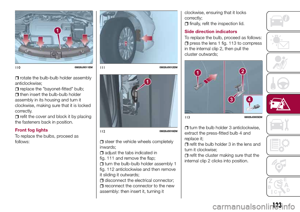
adjust the tabs indicated in
fig. 111 and remove the flap;
turn the bulb-bulb holder assembly 1
fig. 112 anticlockwise and then remove
it sliding it outwards;
disconnect the electrical connector;
reconnect the connector to the new
assembly: then insert it, turning itclockwise, ensuring that it locks
correctly;
finally, refit the inspection lid.
Side direction indicators
To replace the bulb, proceed as follows:
press the lens 1 fig. 113 to compress
in the internal clip 2, then pull the
cluster outwards;
turn the bulb holder 3 anticlockwise,
extract the press-fitted bulb 4 and
replace it;
refit the bulb holder 3 in the lens and
turn it clockwise;
refit the cluster making sure that the
internal clip 2 clicks into position.
11008026J0011EM11108026J0012EM
11208026J0016EM
11308026J0005EM
123
Page 126 of 240
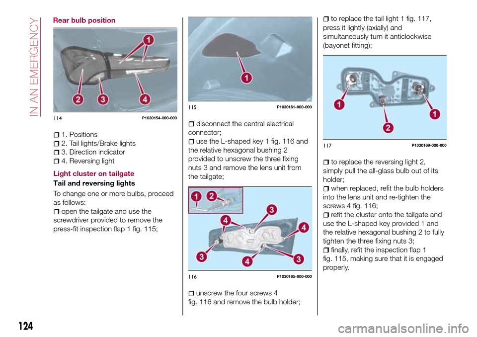
1. Positions
2. Tail lights/Brake lights
3. Direction indicator
4. Reversing light
Light cluster on tailgate
Tail and reversing lights
To change one or more bulbs, proceed
as follows:
open the tailgate and use the
screwdriver provided to remove the
press-fit inspection flap 1 fig. 115;
disconnect the central electrical
connector;
use the L-shaped key 1 fig. 116 and
the relative hexagonal bushing 2
provided to unscrew the three fixing
nuts 3 and remove the lens unit from
the tailgate;
unscrew the four screws 4
fig. 116 and remove the bulb holder;
to replace the tail light 1 fig. 117,
press it lightly (axially) and
simultaneously turn it anticlockwise
(bayonet fitting);
to replace the reversing light 2,
simply pull the all-glass bulb out of its
holder;
when replaced, refit the bulb holders
into the lens unit and re-tighten the
screws 4 fig. 116;
refit the cluster onto the tailgate and
use the L-shaped key provided 1 and
the relative hexagonal bushing 2 to fully
tighten the three fixing nuts 3;
finally, refit the inspection flap 1
fig. 115, making sure that it is engaged
properly.
114P1030154-000-000
115P1030161-000-000
116P1030165-000-000
117P1030169-000-000
124
IN AN EMERGENCY
Rear bulb position
Page 127 of 240
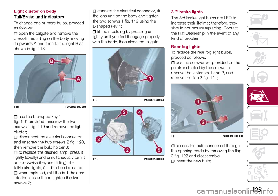
open the tailgate and remove the
press-fit moulding on the body, moving
it upwards A and then to the right B as
shown in fig. 118;
use the L-shaped key 1
fig. 116 provided, unscrew the two
screws 1 fig. 119 and remove the light
cluster;
disconnect the electrical connector
and unscrew the two screws 2 fig. 120,
then remove the bulb holder 3;
to replace the desired lamp, press it
lightly (axially) and simultaneously turn it
anticlockwise (bayonet fitting); 4 -
tail/brake lights, 5 - direction indicators;
when replaced, refit the bulb holders
into the lens unit and tighten the two
screws 2;
connect the electrical connector, fit
the lens unit on the body and tighten
the two screws 1 fig. 119 using the
L-shaped key 1;
fit the moulding by pressing on it
lightly until you feel it engage properly
with the body, then close the tailgate.3
rdbrake lights
The 3rd brake light bulbs are LED to
increase their lifetime; therefore, they
should not require replacing. Contact
the Fiat Dealership in the event of any
kind of problem
Rear fog lights
To replace the rear fog light bulbs,
proceed as follows:
use the screwdriver provided on the
points indicated by the arrows to
rmeove the fasteners 1 and 2, and
remove the flap 3 fig. 121;
access the bulb concerned through
the opening made by removing the flap
3 fig. 122 and disassemble.
insert the new bulb;
118P2000068-000-000
119P1030171-000-000
120P1030172-000-000
121P2000079-000-000
125
Light cluster on body
Tail/Brake and indicators
To change one or more bulbs, proceed
as follows:
Page 128 of 240
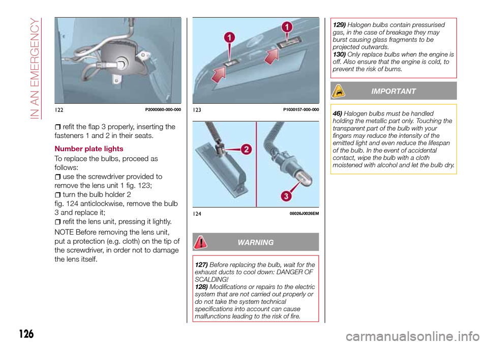
refit the flap 3 properly, inserting the
fasteners 1 and 2 in their seats.
Number plate lights
To replace the bulbs, proceed as
follows:
use the screwdriver provided to
remove the lens unit 1 fig. 123;
turn the bulb holder 2
fig. 124 anticlockwise, remove the bulb
3 and replace it;
refit the lens unit, pressing it lightly.
NOTE Before removing the lens unit,
put a protection (e.g. cloth) on the tip of
the screwdriver, in order not to damage
the lens itself.
WARNING
127)Before replacing the bulb, wait for the
exhaust ducts to cool down: DANGER OF
SCALDING!
128)Modifications or repairs to the electric
system that are not carried out properly or
do not take the system technical
specifications into account can cause
malfunctions leading to the risk of fire.129)Halogen bulbs contain pressurised
gas, in the case of breakage they may
burst causing glass fragments to be
projected outwards.
130)Only replace bulbs when the engine is
off. Also ensure that the engine is cold, to
prevent the risk of burns.
IMPORTANT
46)Halogen bulbs must be handled
holding the metallic part only. Touching the
transparent part of the bulb with your
fingers may reduce the intensity of the
emitted light and even reduce the lifespan
of the bulb. In the event of accidental
contact, wipe the bulb with a cloth
moistened with alcohol and let the bulb dry.122P2000080-000-000123P1030157-000-000
12408026J0026EM
126
IN AN EMERGENCY
Page 135 of 240
CHANGING A WHEEL
JACK
Please note that:
the jack weight is 2.15 kg;
the jack cannot be repaired and in
the event of a fault it must be replaced
by another genuine one;
No tool other than its cranking device
may be fitted on the jack.
Servicing
Prevent any dirt from depositing on
the "worm screw";
Keep the "worm screw" lubricated;
Never modify the jack.
Conditions for non-use
Temperatures below −40°C;
On sandy or muddy ground;
On uneven ground;
On steep roads;
In extreme weather conditions:
thunderstorms, typhoons, hurricanes,
blizzards, storms, etc.
In direct contact with the engine or
for repairs under the vehicle;
On boats.
CHANGING PROCEDURE
135) 136) 137) 138) 139)
49) 50)
Proceed as follows:
stop the car in a position that is not
dangerous for oncoming traffic where
you can change the wheel safely. The
ground must be flat and sufficiently
compact;
stop the engine, engage the hazard
warning lights and the parking brake;
engage first gear or reverse;
wear the reflective safety jacket
before getting out of the car (anyway
comply with the laws in force in the
country you are driving in);
open the boot and if there is a cargo
box, remove it as described in the
“Cargo box” paragraph in the “Getting
to know the car” chapter.
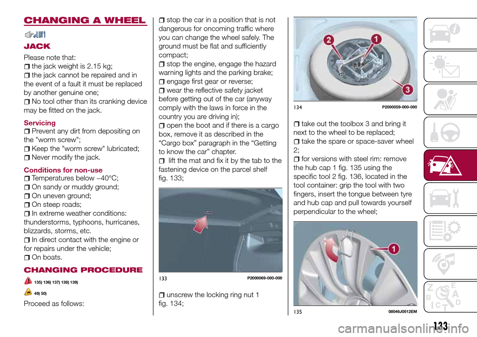
lift the mat and fix it by the tab to the
fastening device on the parcel shelf
fig. 133;
unscrew the locking ring nut 1
fig. 134;
take out the toolbox 3 and bring it
next to the wheel to be replaced;
take the spare or space-saver wheel
2;
for versions with steel rim: remove
the hub cap 1 fig. 135 using the
specific tool 2 fig. 136, located in the
tool container: grip the tool with two
fingers, insert the tongue between tyre
and hub cap and pull towards yourself
perpendicular to the wheel;
133P2000069-000-000
134P2000059-000-000
13508046J0012EM
133