2016 FIAT TIPO 5DOORS STATION WAGON ESP
[x] Cancel search: ESPPage 111 of 240

OPERATION WITH A
TRAILER
The operation of the sensors is
automatically deactivated when the
trailer's electrical connection is inserted
in the vehicle's tow hook socket.
Sensors are reactivated on removing
the trailer's electrical connection.
IMPORTANT NOTES
When parking, take the utmost care
over obstacles that may be above or
under the sensor. Objects close to the
vehicle are not detected under certain
circumstances and could therefore
cause damage to the vehicle or be
damaged.
Some conditions may influence the
performance of the parking system:
reduced sensor sensitivity and a
reduction in the parking assistance
system performance could be due to
the presence of: ice, snow, mud, paint,
etc. on the surface of the sensor;
the sensor may detect a
non-existent obstacle ("echo
interference") due to mechanical
interference, for example when washing
the vehicle, in rain (strong wind), hail;
the signals sent by the sensor can
also be altered by the presence of
ultrasonic systems (e.g. pneumatic
brake systems of trucks or pneumatic
drills) near the vehicle;
parking assistance system
performance can also be influenced by
the position of the sensors, for example
due to a change in the ride setting
(caused by wear to the shock
absorbers, suspension), or by changing
tyres, overloading the vehicle or fitting
specific trims that require the vehicle to
be lowered;
the presence of a tow hook without
trailer, which may interfere with the
correct operation of the parking
sensors;
the presence of adhesives on the
sensors. Therefore, take care not to
place adhesives on the sensors.
WARNING
120)Parking and other potentially
dangerous manoeuvres are, however,
always the driver’s responsibility. When
performing these operations, always make
sure that there are no other people
(especially children) or animals on the route
you want to take. The parking sensors are
an aid for the driver, but the driver must
never allow their attention to lapse during
potentially dangerous manoeuvres, even
those executed at low speeds.
IMPORTANT
41)The sensors must be clean of mud,
dirt, snow or ice in order for the system to
operate correctly. Be careful not to scratch
or damage the sensors while cleaning
them. Avoid using dry, rough or hard
cloths. The sensors should be washed
using clean water with the addition of car
shampoo if necessary. When using special
washing equipment such as high pressure
jets or steam cleaning, clean the sensors
very quickly keeping the jet more than 10
cm away.
42)Have interventions on the bumper in
the area of the sensors carried out only by
a Fiat Dealership. Interventions on the
bumper that are not carried out properly
may compromise the operation of the
parking sensors
43)Only have the bumpers repainted or
any retouches to the paintwork in the area
of the sensors carried out by a Fiat
Dealership. Incorrect paint application
could affect the operation of the parking
sensors.
109
Page 114 of 240

IMPORTANT NOTES
IMPORTANT In some circumstances,
such as with ice, snow or mud on the
surface of the camera, the camera
sensitivity may be reduced.
IMPORTANT When parking, take the
utmost care over obstacles that may be
above or under the camera range.
WARNING
121)Parking and other potentially
dangerous manoeuvres are, however,
always the driver’s responsibility. While
carrying out these manoeuvres, always
make sure that no people (especially
children) or animals are in the area
concerned. The camera is an aid for the
driver, but the driver must never allow
his/her attention to lapse during potentially
dangerous manoeuvres, even those
executed at low speeds. Always keep a
slow speed, so as to promptly brake in the
case of obstacles.
IMPORTANT
44)It is vital, for correct operation, that the
camera is always kept clean and free from
any mud, dirt, snow or ice. Be careful not
to scratch or damage the camera while
cleaning it. Avoid using dry, rough or hard
cloths. The camera must be washed using
clean water, with the addition of car
shampoo if necessary. In washing stations
which use steam or high-pressure jets,
clean the camera quickly, keeping the
nozzle more than 10 cm away from the
sensors. Also, do not apply stickers to the
camera.
TOWING TRAILERS
IMPORTANT NOTES
122) 123)
For towing caravans or trailers the
vehicle must be fitted with an approved
tow hook and an adequate electrical
system. Should aftermarket installation
be requested, this must be carried out
by specialists.
Install any specific and/or additional
door mirrors as specified by the
Highway Code.
Remember that, when towing a trailer,
steep hills are harder to climb, braking
distances increase and overtaking takes
longer depending on the overall weight
of the trailer.
Engage a low gear when driving
downhill, rather than constantly using
the brake.
The weight the trailer exerts on the
vehicle tow hook reduces the vehicle's
loading capacity by the same amount.
To make sure that the maximum
towable weight is not exceeded (given
in the vehicle registration document)
account should be taken of the fully
laden trailer, including accessories and
luggage.
Do not exceed the speed limits specific
112
STARTING AND DRIVING
Page 119 of 240
HAZARD WARNING
LIGHTS
CONTROL
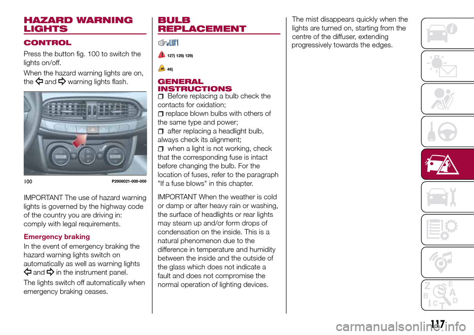
Press the button fig. 100 to switch the
lights on/off.
When the hazard warning lights are on,
the
andwarning lights flash.
IMPORTANT The use of hazard warning
lights is governed by the highway code
of the country you are driving in:
comply with legal requirements.
Emergency braking
In the event of emergency braking the
hazard warning lights switch on
automatically as well as warning lights
andin the instrument panel.
The lights switch off automatically when
emergency braking ceases.
BULB
REPLACEMENT
127) 128) 129)
46)
GENERAL
INSTRUCTIONS
Before replacing a bulb check the
contacts for oxidation;
replace blown bulbs with others of
the same type and power;
after replacing a headlight bulb,
always check its alignment;
when a light is not working, check
that the corresponding fuse is intact
before changing the bulb. For the
location of fuses, refer to the paragraph
"If a fuse blows" in this chapter.
IMPORTANT When the weather is cold
or damp or after heavy rain or washing,
the surface of headlights or rear lights
may steam up and/or form drops of
condensation on the inside. This is a
natural phenomenon due to the
difference in temperature and humidity
between the inside and the outside of
the glass which does not indicate a
fault and does not compromise the
normal operation of lighting devices.The mist disappears quickly when the
lights are turned on, starting from the
centre of the diffuser, extending
progressively towards the edges.
100P2000021-000-000
117
Page 128 of 240
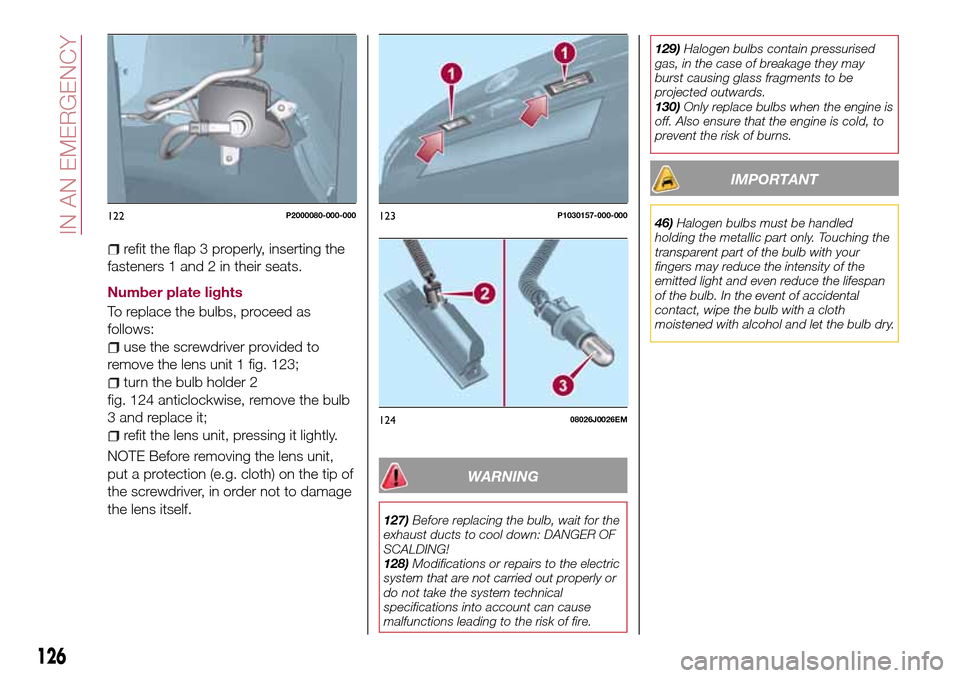
refit the flap 3 properly, inserting the
fasteners 1 and 2 in their seats.
Number plate lights
To replace the bulbs, proceed as
follows:
use the screwdriver provided to
remove the lens unit 1 fig. 123;
turn the bulb holder 2
fig. 124 anticlockwise, remove the bulb
3 and replace it;
refit the lens unit, pressing it lightly.
NOTE Before removing the lens unit,
put a protection (e.g. cloth) on the tip of
the screwdriver, in order not to damage
the lens itself.
WARNING
127)Before replacing the bulb, wait for the
exhaust ducts to cool down: DANGER OF
SCALDING!
128)Modifications or repairs to the electric
system that are not carried out properly or
do not take the system technical
specifications into account can cause
malfunctions leading to the risk of fire.129)Halogen bulbs contain pressurised
gas, in the case of breakage they may
burst causing glass fragments to be
projected outwards.
130)Only replace bulbs when the engine is
off. Also ensure that the engine is cold, to
prevent the risk of burns.
IMPORTANT
46)Halogen bulbs must be handled
holding the metallic part only. Touching the
transparent part of the bulb with your
fingers may reduce the intensity of the
emitted light and even reduce the lifespan
of the bulb. In the event of accidental
contact, wipe the bulb with a cloth
moistened with alcohol and let the bulb dry.122P2000080-000-000123P1030157-000-000
12408026J0026EM
126
IN AN EMERGENCY
Page 130 of 240
at the same time slowly rotate the
screw anticlockwise, until resistance is
encountered (do not overtighten);
slowly release the screw;
opening is indicated by the entire
screw head coming out of its housing;
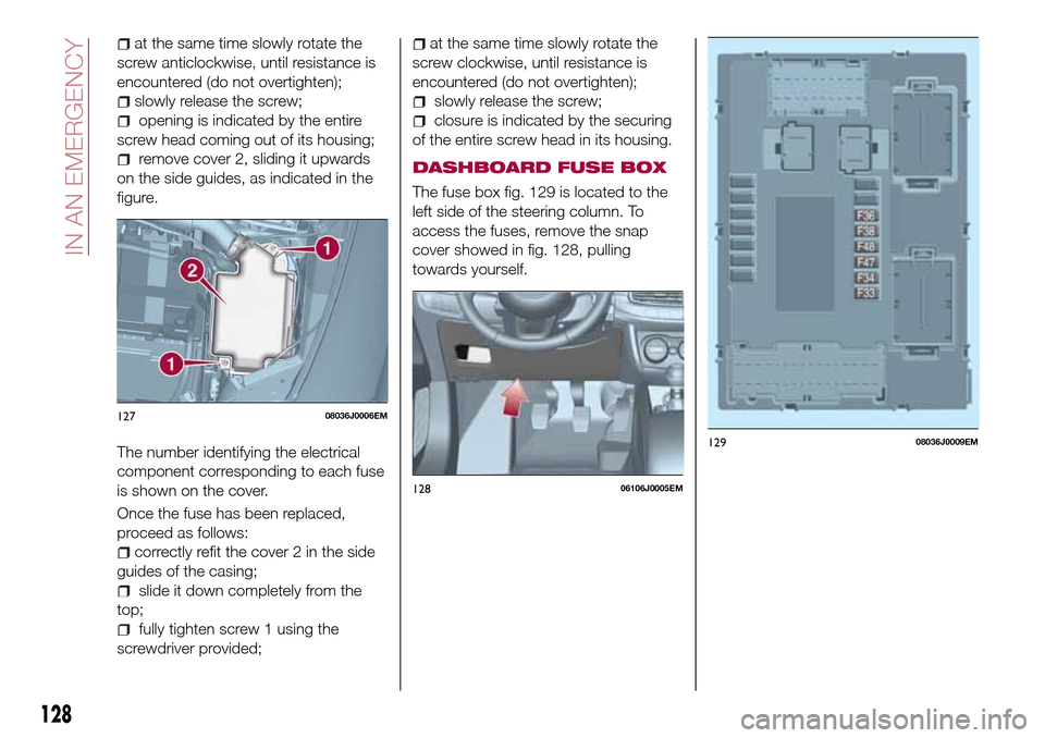
remove cover 2, sliding it upwards
on the side guides, as indicated in the
figure.
The number identifying the electrical
component corresponding to each fuse
is shown on the cover.
Once the fuse has been replaced,
proceed as follows:
correctly refit the cover 2 in the side
guides of the casing;
slide it down completely from the
top;
fully tighten screw 1 using the
screwdriver provided;
at the same time slowly rotate the
screw clockwise, until resistance is
encountered (do not overtighten);
slowly release the screw;
closure is indicated by the securing
of the entire screw head in its housing.
DASHBOARD FUSE BOX
The fuse box fig. 129 is located to the
left side of the steering column. To
access the fuses, remove the snap
cover showed in fig. 128, pulling
towards yourself.
12708036J0006EM
12806106J0005EM
12908036J0009EM
128
IN AN EMERGENCY
Page 137 of 240
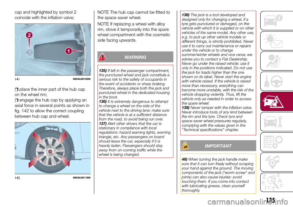
cap and highlighted by symbol 2
coincide with the inflation valve;
place the inner part of the hub cap
on the wheel rim;
engage the hub cap by applying an
axial force in several points as shown in
fig. 142 to allow the correct coupling
between hub cap and wheel.NOTE The hub cap cannot be fitted to
the space-saver wheel.
NOTE If replacing a wheel with alloy
rim, stove it temporarily into the spare
wheel compartment with the cosmetic
side facing upwards.
WARNING
135)If left in the passenger compartment,
the punctured wheel and jack constitute a
serious risk to the safety of occupants in
the event of accidents or sharp braking.
Therefore, always place both the jack and
punctured wheel in the dedicated housing
in the boot.
136)It is extremely dangerous to attempt
to change a wheel on the side of the
vehicle next to the driving lane: make sure
that the vehicle is at a sufficient distance
from the road, to avoid being run over.
137)Alert other drivers that the car is
stationary in compliance with local
regulations: hazard warning lights, warning
triangle, etc. Any passengers on board
should leave the car, especially if it is
heavily laden. Passengers should stay
away from on-coming traffic while the
wheel is being changed.138)The jack is a tool developed and
designed only for changing a wheel, if a
tyre gets punctured or damaged, on the
vehicle with which it is supplied or on other
vehicles of the same model. Any other use,
e.g. to jack up other vehicle models or
different things, is strictly prohibited. Never
use it to carry out maintenance or repairs
under the vehicle or to change
summer/winter wheels and vice versa: we
advise you to contact a Fiat Dealership.
Never go under the raised vehicle: use it
only in the positions indicated. Do not use
the jack for loads higher than the one
shown on its label. Never start the engine
with vehicle raised. If the vehicle is raised
more than necessary, everything can
become more unstable, with the risk of the
vehicle dropping violently. Thus, lift the
vehicle only as needed in order to access
the spare wheel.
139)Never tamper with the inflation valve.
Never introduce tools of any kind between
the rim and the tyre. Check tyre and
space-saver wheel pressures regularly,
complying with the values given in the
"Technical specifications" chapter.
IMPORTANT
49)When turning the jack handle make
sure that it can turn freely without scraping
your hand against the ground. The moving
components of the jack ("worm screw" and
joints) can also cause injuries: avoid
touching them. If you come into contact
with lubricating grease, clean yourself
thoroughly.
14108046J0010EM
14208046J0011EM
135
Page 149 of 240
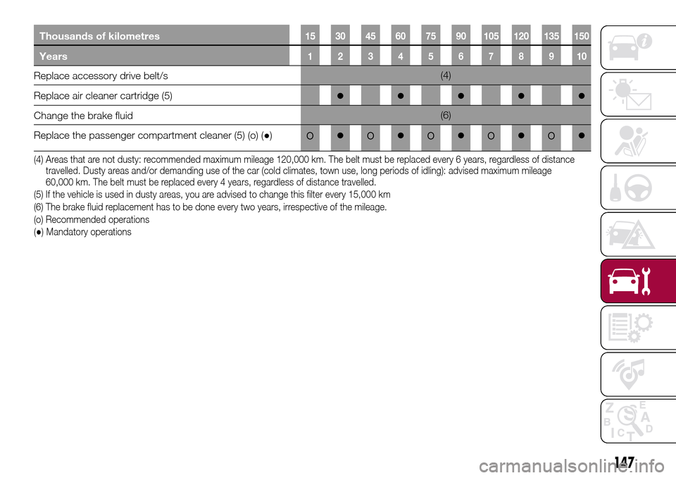
Thousands of kilometres15 30 45 60 75 90 105 120 135 150
Years12345678910
Replace accessory drive belt/s(4)
Replace air cleaner cartridge (5)
●●●●●
Change the brake fluid(6)
Replace the passenger compartment cleaner (5) (o) (●)
o●o●o●o●o●
(4) Areas that are not dusty: recommended maximum mileage 120,000 km. The belt must be replaced every 6 years, regardless of distance
travelled. Dusty areas and/or demanding use of the car (cold climates, town use, long periods of idling): advised maximum mileage
60,000 km. The belt must be replaced every 4 years, regardless of distance travelled.
(5) If the vehicle is used in dusty areas, you are advised to change this filter every 15,000 km
(6) The brake fluid replacement has to be done every two years, irrespective of the mileage.
(o) Recommended operations
(●) Mandatory operations
147
Page 152 of 240
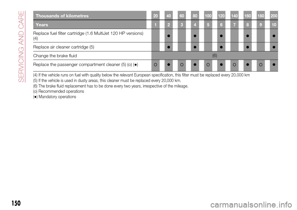
Thousands of kilometres20 40 60 80 100 120 140 160 180 200
Years12345678910
Replace fuel filter cartridge (1.6 MultiJet 120 HP versions)
(4)●●●●●
Replace air cleaner cartridge (5)●●●●●
Change the brake fluid(6)
Replace the passenger compartment cleaner (5) (o) (●)
o●o●o●o●o●
(4) If the vehicle runs on fuel with quality below the relevant European specification, this filter must be replaced every 20,000 km
(5) If the vehicle is used in dusty areas, this cleaner must be replaced every 20,000 km.
(6) The brake fluid replacement has to be done every two years, irrespective of the mileage.
(o) Recommended operations
(●) Mandatory operations
150
SERVICING AND CARE