2016 FIAT TIPO 5DOORS STATION WAGON brake light
[x] Cancel search: brake lightPage 109 of 240

ELECTRONIC CRUISE
CONTROL MODE
Electronic Cruise Control mode is
available for travelling at constant speed
in addition to the Adaptive Cruise
Control (ACC) mode.
If the Adaptive Cruise Control (ACC)
function is implemented on the vehicle,
the electronic Cruise Control works in
the same manner as the ACC (by
pressing the
button of the Cruise
Control) with the difference that:
it does not hold the distance from the
vehicle ahead;
the device keeps working if the
radar sensor is obstructed.
Before returning to the previously set
speed, bring the speed close to that
value, press the RES (Resume) button
and then release it.
WARNING
114)Pay the utmost attention while driving
at all times and be always ready to press
the brakes if needed.
115)The system is an aid for the driver,
who must always pay full attention while
driving. The responsibility always rests with
the driver, who must take into account the
traffic conditions in order to drive in
complete safety. The driver must always
maintain a safe distance from the vehicle in
front.
116)The device is not activated in
presence of pedestrians, oncoming
vehicles in the opposite direction of travel
or moving in the crosswise direction and
stationary objects (e.g. a vehicle standing
in a queue or a broken down vehicle).
117)The device cannot take account of
road, traffic and weather conditions, and
conditions of poor visibility (e.g. fog).
118)The device cannot take account of
road, traffic and weather conditions, and
conditions of poor visibility (e.g. fog).
119)The device cannot apply the
maximum braking force: the car will not be
stopped completely.
IMPORTANT
34)The system may have limited or absent
operation due to weather conditions such
as: heavy rain, hail, thick fog, heavy snow.35)The section of the bumper before the
sensor must not be covered with
adhesives, auxiliary headlights or any other
object.
36)Operation can be adversely affected by
any structural change made to the vehicle,
such as a modification to the front
geometry, tyre change, or a heavier load
than the standard load of the vehicle.
37)Incorrect repairs made on the front part
of the vehicle (e.g. bumper, chassis) may
alter the position of the radar sensor, and
adversely affect its operation. Go to a Fiat
Dealership for any operation of this type.
38)Do not tamper nor operate on the radar
sensor. In the event of a sensor failure,
contact a Fiat Dealership.
39)Do not wash with high-pressure jets in
the bumper lower area: in particular do not
operate on the system's electrical
connector.
40)Be careful in the case of repairs and
new paintings in the area around the
sensor (panel covering the sensor on the
left side of the bumper). In the event of a
frontal impact the sensor may automatically
deactivate and display a warning to indicate
that the sensor needs to be repaired. Even
without a malfunction warning, deactivate
the system operation if you think that the
position of the radar sensor has changed
(e.g. due to low-speed frontal impact as
during parking manoeuvres). In these
cases, go to a Fiat Dealership to have the
radar sensor realigned or replaced.
94P2000046-000-000
107
Page 115 of 240

to each country you are driving in, in the
case of vehicles towing trailers. In any
case, the top speed must not exceed
100 km/h.
Any electric brake must be powered
directly by the battery through a cable
with a cross-section of no less than 2.5
mm
2.
In addition to the electrical branches,
the vehicle electrical system can only be
connected to the supply cable for an
electric brake and to the cable for an
internal light for the trailer, not
exceeding 15 W. For connections, use
the preset control unit with a battery
cable with section not less than 2.5 mm
2.
IMPORTANT The use of auxiliary loads
other than external lights (e.g. electric
brake) must take place with engine
running.
INSTALLING A TOW
HOOK
To install a tow hook contact a Fiat
Dealership.
WARNING
122)The ABS with which the car is
equipped will not control the braking
system of the trailer. Particular caution is
required on slippery roads.123)Never modify the braking system of
the vehicle to control the trailer brake. The
trailer braking system must be fully
independent of the car’s hydraulic system.
REFUELLING THE
VEHICLE
124) 125) 126)
Before refuelling, make sure that the
fuel type is correct.
Also stop the engine before refuelling.
PETROL ENGINES
Only use unleaded petrol with a number
of octanes (R.O.N.) not lower than 95
(EN228 specification).
DIESEL ENGINES
45)
Only use Diesel for motor vehicles
(EN590 specification).
When using or parking the vehicle for a
long time in the mountains or cold
areas, it is advisable to refuel using
locally available Diesel. In this case, it is
also advisable to keep the tank over
50% full.
REFUELLING CAPACITY
To ensure that you fill the tank
completely, top up twice after the first
click of the fuel supply gun.
Further top-ups could cause faults in
the fuel feeding system.
113
Page 121 of 240
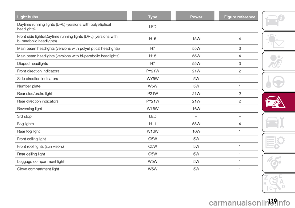
Light bulbs Type Power Figure reference
Daytime running lights (DRL) (versions with polyelliptical
headlights)LED – –
Front side lights/Daytime running lights (DRL) (versions with
bi-parabolic headlights)H15 15W 4
Main beam headlights (versions with polyelliptical headlights) H7 55W 3
Main beam headlights (versions with bi-parabolic headlights) H15 55W 4
Dipped headlights H7 55W 3
Front direction indicators PY21W 21W 2
Side direction indicators WY5W 5W 1
Number plate W5W 5W 1
Rear side/brake light P21W 21W 2
Rear direction indicators PY21W 21W 2
Reversing light W16W 16W 1
3rd stop LED – –
Fog lights H11 55W 4
Rear fog light W16W 16W 1
Front ceiling light C5W 5W 1
Front roof lights (sun visors) C5W 5W 1
Rear ceiling light C5W 6W 1
Luggage compartment light W5W 5W 1
Glove compartment light W5W 5W 1
119
Page 126 of 240
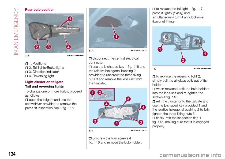
1. Positions
2. Tail lights/Brake lights
3. Direction indicator
4. Reversing light
Light cluster on tailgate
Tail and reversing lights
To change one or more bulbs, proceed
as follows:
open the tailgate and use the
screwdriver provided to remove the
press-fit inspection flap 1 fig. 115;
disconnect the central electrical
connector;
use the L-shaped key 1 fig. 116 and
the relative hexagonal bushing 2
provided to unscrew the three fixing
nuts 3 and remove the lens unit from
the tailgate;
unscrew the four screws 4
fig. 116 and remove the bulb holder;
to replace the tail light 1 fig. 117,
press it lightly (axially) and
simultaneously turn it anticlockwise
(bayonet fitting);
to replace the reversing light 2,
simply pull the all-glass bulb out of its
holder;
when replaced, refit the bulb holders
into the lens unit and re-tighten the
screws 4 fig. 116;
refit the cluster onto the tailgate and
use the L-shaped key provided 1 and
the relative hexagonal bushing 2 to fully
tighten the three fixing nuts 3;
finally, refit the inspection flap 1
fig. 115, making sure that it is engaged
properly.
114P1030154-000-000
115P1030161-000-000
116P1030165-000-000
117P1030169-000-000
124
IN AN EMERGENCY
Rear bulb position
Page 127 of 240
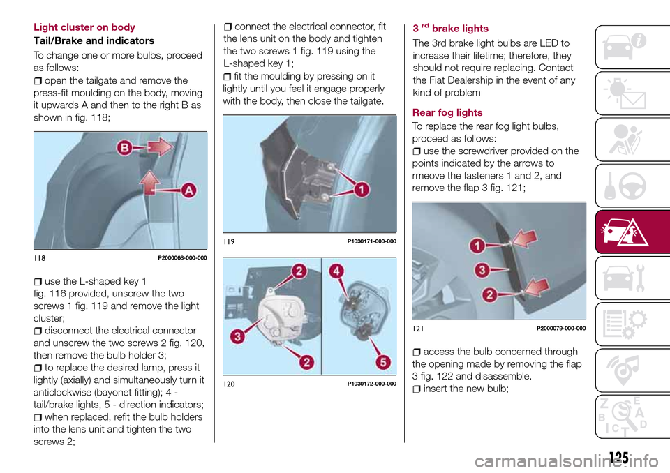
open the tailgate and remove the
press-fit moulding on the body, moving
it upwards A and then to the right B as
shown in fig. 118;
use the L-shaped key 1
fig. 116 provided, unscrew the two
screws 1 fig. 119 and remove the light
cluster;
disconnect the electrical connector
and unscrew the two screws 2 fig. 120,
then remove the bulb holder 3;
to replace the desired lamp, press it
lightly (axially) and simultaneously turn it
anticlockwise (bayonet fitting); 4 -
tail/brake lights, 5 - direction indicators;
when replaced, refit the bulb holders
into the lens unit and tighten the two
screws 2;
connect the electrical connector, fit
the lens unit on the body and tighten
the two screws 1 fig. 119 using the
L-shaped key 1;
fit the moulding by pressing on it
lightly until you feel it engage properly
with the body, then close the tailgate.3
rdbrake lights
The 3rd brake light bulbs are LED to
increase their lifetime; therefore, they
should not require replacing. Contact
the Fiat Dealership in the event of any
kind of problem
Rear fog lights
To replace the rear fog light bulbs,
proceed as follows:
use the screwdriver provided on the
points indicated by the arrows to
rmeove the fasteners 1 and 2, and
remove the flap 3 fig. 121;
access the bulb concerned through
the opening made by removing the flap
3 fig. 122 and disassemble.
insert the new bulb;
118P2000068-000-000
119P1030171-000-000
120P1030172-000-000
121P2000079-000-000
125
Light cluster on body
Tail/Brake and indicators
To change one or more bulbs, proceed
as follows:
Page 135 of 240
CHANGING A WHEEL
JACK
Please note that:
the jack weight is 2.15 kg;
the jack cannot be repaired and in
the event of a fault it must be replaced
by another genuine one;
No tool other than its cranking device
may be fitted on the jack.
Servicing
Prevent any dirt from depositing on
the "worm screw";
Keep the "worm screw" lubricated;
Never modify the jack.
Conditions for non-use
Temperatures below −40°C;
On sandy or muddy ground;
On uneven ground;
On steep roads;
In extreme weather conditions:
thunderstorms, typhoons, hurricanes,
blizzards, storms, etc.
In direct contact with the engine or
for repairs under the vehicle;
On boats.
CHANGING PROCEDURE
135) 136) 137) 138) 139)
49) 50)
Proceed as follows:
stop the car in a position that is not
dangerous for oncoming traffic where
you can change the wheel safely. The
ground must be flat and sufficiently
compact;
stop the engine, engage the hazard
warning lights and the parking brake;
engage first gear or reverse;
wear the reflective safety jacket
before getting out of the car (anyway
comply with the laws in force in the
country you are driving in);
open the boot and if there is a cargo
box, remove it as described in the
“Cargo box” paragraph in the “Getting
to know the car” chapter.
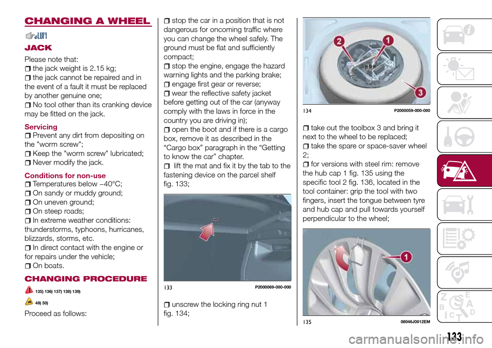
lift the mat and fix it by the tab to the
fastening device on the parcel shelf
fig. 133;
unscrew the locking ring nut 1
fig. 134;
take out the toolbox 3 and bring it
next to the wheel to be replaced;
take the spare or space-saver wheel
2;
for versions with steel rim: remove
the hub cap 1 fig. 135 using the
specific tool 2 fig. 136, located in the
tool container: grip the tool with two
fingers, insert the tongue between tyre
and hub cap and pull towards yourself
perpendicular to the wheel;
133P2000069-000-000
134P2000059-000-000
13508046J0012EM
133
Page 147 of 240
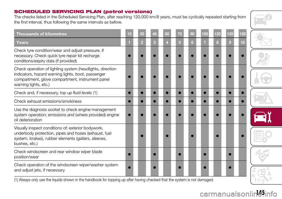
SCHEDULED SERVICING PLAN (petrol versions)
The checks listed in the Scheduled Servicing Plan, after reaching 120,000 km/8 years, must be cyclically repeated starting from
the first interval, thus following the same intervals as before.
Thousands of kilometres15 30 45 60 75 90 105 120 135 150
Years12345678910
Check tyre condition/wear and adjust pressure, if
necessary. Check quick tyre repair kit recharge
conditions/expiry date (if provided)
●●●●●●●●●●
Check operation of lighting system (headlights, direction
indicators, hazard warning lights, boot, passenger
compartment, glove compartment, instrument panel
warning lights, etc.)
●●●●●●●●●●
Check and, if necessary, top up fluid levels (1)●●●●●●●●●●
Check exhaust emissions/smokiness●●●●●●●●●●
Use the diagnosis socket to check engine management
system operation; emissions and (where provided) engine
oil deterioration
●●●●●●●●●●
Visually inspect conditions of: exterior bodywork,
underbody protection, pipes and hoses (exhaust, fuel
system, brakes), rubber elements (gaiters, sleeves,
bushes, etc.)
●●●●●
Check windscreen and rear window wiper blade
position/wear●●●●●
Check operation of the windscreen wiper/washer system
and adjust jets, if necessary●●●●●
(1) Always only use the liquids shown in the handbook for topping up after having checked that the system is not damaged.
145
Page 150 of 240
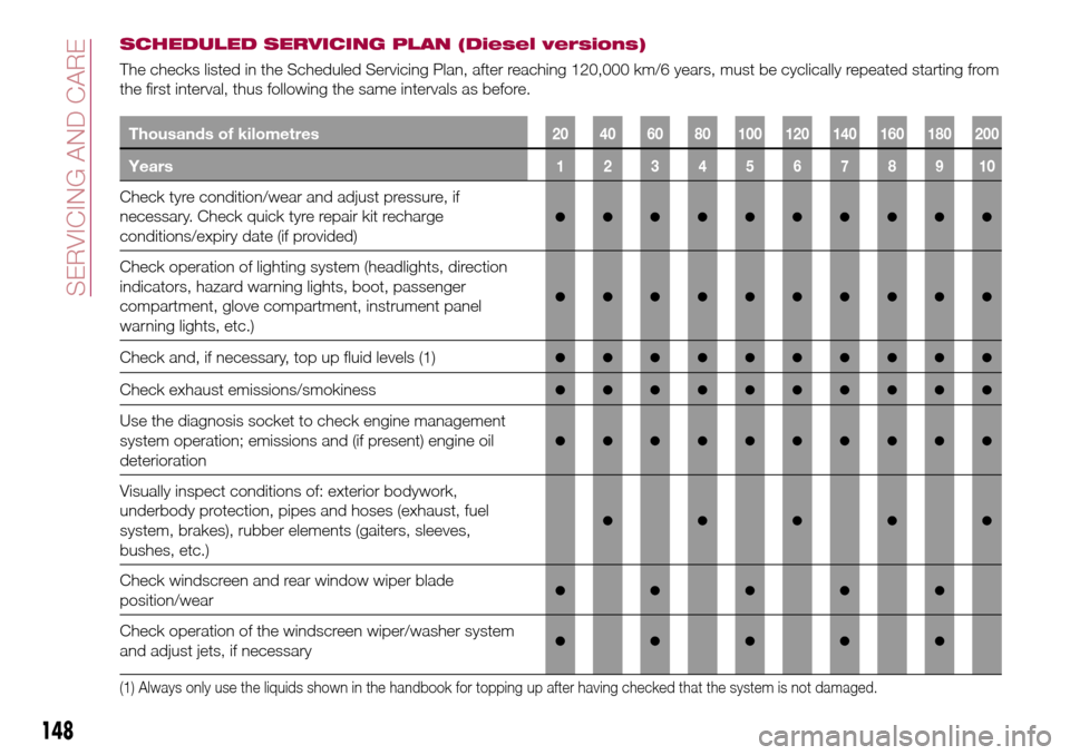
SCHEDULED SERVICING PLAN (Diesel versions)
The checks listed in the Scheduled Servicing Plan, after reaching 120,000 km/6 years, must be cyclically repeated starting from
the first interval, thus following the same intervals as before.
Thousands of kilometres20 40 60 80 100 120 140 160 180 200
Years12345678910
Check tyre condition/wear and adjust pressure, if
necessary. Check quick tyre repair kit recharge
conditions/expiry date (if provided)
●●●●●●●●●●
Check operation of lighting system (headlights, direction
indicators, hazard warning lights, boot, passenger
compartment, glove compartment, instrument panel
warning lights, etc.)
●●●●●●●●●●
Check and, if necessary, top up fluid levels (1)●●●●●●●●●●
Check exhaust emissions/smokiness●●●●●●●●●●
Use the diagnosis socket to check engine management
system operation; emissions and (if present) engine oil
deterioration
●●●●●●●●●●
Visually inspect conditions of: exterior bodywork,
underbody protection, pipes and hoses (exhaust, fuel
system, brakes), rubber elements (gaiters, sleeves,
bushes, etc.)
●●●●●
Check windscreen and rear window wiper blade
position/wear●●●●●
Check operation of the windscreen wiper/washer system
and adjust jets, if necessary●●●●●
(1) Always only use the liquids shown in the handbook for topping up after having checked that the system is not damaged.
148
SERVICING AND CARE