2016 FIAT TIPO 4DOORS parking brake
[x] Cancel search: parking brakePage 113 of 204

CHANGING A WHEEL
JACK
132)
37)
Please note that:
the jack weight is 2.15 kg;
the jack cannot be repaired and in
the event of a fault it must be replaced
by another genuine one;
No tool other than its cranking device
may be fitted on the jack.
Servicing
Prevent any dirt from depositing on
the "worm screw";
Keep the "worm screw" lubricated;
Never modify the jack.
Conditions for non-use
Temperatures below −40°C;
On sandy or muddy ground;
On uneven ground;
On steep roads;
In extreme weather conditions:
thunderstorms, typhoons, hurricanes,
blizzards, storms, etc.
In direct contact with the engine or
for repairs under the vehicle.
On boats.
CHANGING PROCEDURE
127) 128) 129) 130) 131)
35) 36)
Proceed as follows:
stop the car in a position that is not
dangerous for oncoming traffic where
you can change the wheel safely. The
ground must be flat and sufficiently
compact;
stop the engine, engage the hazard
warning lights and the parking brake;
engage first gear or reverse or, for
versions with automatic transmission (if
present), move the lever to position P
(Park);
wear the reflective safety jacket
before getting out of the car (anyway
comply with the laws in force in the
country you are driving in);
open the luggage compartment and
lift up the mat;
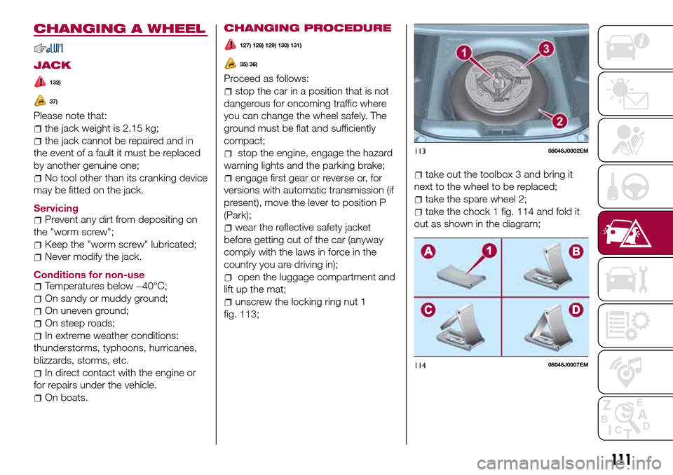
unscrew the locking ring nut 1
fig. 113;
take out the toolbox 3 and bring it
next to the wheel to be replaced;
take the spare wheel 2;
take the chock 1 fig. 114 and fold it
out as shown in the diagram;
11308046J0002EM
11408046J0007EM
111
Page 117 of 204

37)When turning the jack handle make
sure that it can turn freely without scraping
your hand against the ground. The moving
components of the jack ("worm screw" and
joints) can also cause injuries: avoid
touching them. If you come into contact
with lubricating grease, clean yourself
thoroughly.FIX&GO AUTOMATIC
KIT
(where provided)
DESCRIPTION
133)
38) 39)
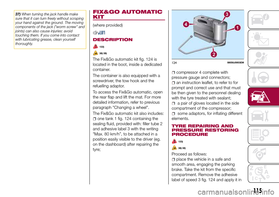
The Fix&Go automatic kit fig. 124 is
located in the boot, inside a dedicated
container.
The container is also equipped with a
screwdriver, the tow hook and the
refuelling adaptor.
To access the Fix&Go automatic, open
the rear flap and lift the mat. For more
detailed information, refer to previous
paragraph "Changing a wheel".
The Fix&Go automatic kit also includes:
one tank 1 fig. 124 containing the
sealing fluid, provided with: filler tube 2
and adhesive label 3 with the writing
"Max. 80 km/h”, to be attached in a
position easily visible to the driver (eg.
on the dashboard) after repairing the
tyre;
compressor 4 complete with
pressure gauge and connectors;
an instruction leaflet, to refer to for
prompt and correct use and that must
be then given to the personnel dealing
with the tyre treated with sealant;
a pair of gloves located in the side
compartment of the compressor;
some adaptors, for inflating different
elements.
TYRE REPAIRING AND
PRESSURE RESTORING
PROCEDURE
133)
38) 39)
Proceed as follows:
place the vehicle in a safe and
smooth area, engaging the parking
brake. Take the kit from the specific
compartment. Remove the adhesive
label of speed 3 fig. 124 and apply it in
12408056J0003EM
115
Page 118 of 204

a visible position. Wear the protective
gloves provided. Remove the cap from
the valve of the punctured tyre and
connect and firmly tighten the
transparent tube of the sealing fluid 1
fig. 125;
ensure that the on-off button is in0
(OFF) position. If provided, open the
cover of the compressor 4 fig. 124 and
insert the electrical connector in the
12V socket of the vehicle fig. 126,
switch on the vehicle engine;
activate the compressor moving
on-off button toI(ON) position. When
the pressure gauge shows the vehicle
required pressure (see section “Wheels”
under “Technical data” chapter), switch
off the compressor moving on-off
button to0position. If after 5 minutes
from the compressor ignition, the
pressure gauge indicates a pressure
less than 1.8 bar / 26 psi, switch off thecompressor, disconnect the sealing
fluid tube from the tyre valve, re-screw
the valve cap and move the vehicle
about 10 meters to allow the
distribution of sealing fluid in the tyre.
Securely stop the vehicle and repeat
the operation above until reaching the
required pressure. If after other 5 min.
from the compressor ignition, the
pressure gauge still indicates a pressure
lower than 1.8 bar / 26 psi, the TYRE IS
TOO DAMAGED AND CANNOT BE
REPAIRED. Remove and place the kit in
the specific compartment and contact a
Fiat Dealership;
if the required pressure is reached,
restart driving. Do not exceed 80 km/h.
Avoid sudden acceleration or braking.
After driving for about 8 km / 5 miles,
place the vehicle in a safe and smooth
area, engaging the parking brake. Pick
up the kit, ensure the on-off button is in0position, insert the electrical
connector in the vehicle 12V socket.
Remove the cap from the valve of
repaired tyre, disconnect and pull out
the black inflation tube 1 fig. 127,
connect and block it with the stack to
the valve. Inspect the pressure gauge to
check the tyre pressure;
if the pressure indicated is lower than
1.8 bar / 26 psi, the TYRE IS TOO
DAMAGED AND CANNOT BE
REPAIRED. Remove and place the kit in
the specific compartment and contact a
Fiat Dealership;
if the pressure indicated is equal to or
higher than 1.8 bar / 26 psi, switch on
the compressor and reach the required
pressure. Disconnect and replace the
kit in the specific compartment.
Carefully drive and reach the Fiat
Dealership as soon as possible;
12508056J0004EM
12608056J0002EM
12708056J0006EM
116
IN AN EMERGENCY
Page 119 of 204

WARNING
133)The information required by the
applicable regulation is indicated on the
Fix&Go kit package label. Compliance with
the indications on the label is an essential
condition to ensure the safety and the
effectiveness of the Fix&Go kit. Carefully
read the label before use, avoid improper
use. Fix&Go is subject to expiration and
must be replaced periodically. The kit
should be used by adults and cannot be
used by children.
IMPORTANT
38)Show the package and the label to the
personnel charged with handling the tyre
treated with the tyre repair kit.
39)Fix&Go provides a temporary repair,
therefore the tyre must be examined and
repaired by a specialist as soon as
possible. The sealing fluid is effective at
temperatures between -40°C and +50°C. It
is possible to repair tyres which have been
damaged on tread up to a diameter of
4mm; however, tyres damaged on their
side cannot be repaired. Before using
Fix&Go kit, ensure that the tyre isn't
excessively damaged and that the rim is in
good condition, otherwise do not use it and
contact a Fiat Dealership. Do not remove
foreign bodies from the tyre. Do not let the
compressor turned on for more than 20
consecutive minutes - overheating hazard.
EMERGENCY
STARTING
If the battery is flat, a jump starting can
be performed using the battery and the
cables of another vehicle, or using an
auxiliary battery. In all cases, the battery
used must have a capacity equal to or
a little higher than the flat one.
40)
IMPORTANT NOTES
Do not use an auxiliary battery or any
other source of external supply with a
voltage above 12 V: the battery, the
starter, the alternator and the electrical
system of the vehicle could be
damaged.
Do not attempt jump starting if the
battery is frozen. The battery could
break and explode!
PREPARATION TO JUMP
STARTING
The vehicle battery is located in the
engine compartment, behind the left
light cluster.
134) 135) 136) 137)
IMPORTANT The positive terminal (+) of
the battery is shielded by a protective
element. Raise it to access the terminal.
Proceed as follows:
operate the parking brake, move the
lever to P (Park), for versions equipped
with automatic transmission (if present),
or neutral, for versions with manual
gearbox, then set the ignition device to
STOP;
switch off all the other electrical
devices in the vehicle;
should you be using the battery of
another vehicle, park the other vehicle
within the range of the cables used for
the connection, operate the parking
brake and ensure that its ignition is off.
IMPORTANT Never connect the
negative terminals of the two batteries
directly! If the auxiliary battery is
installed on another vehicle, check that
there is no accidental contact of metal
parts between the two vehicles, since
an earth connection may result, with
the risk of serious injury to any people
who may be nearby.
IMPORTANT If the procedure below is
carried out incorrectly, it can cause
severe injury to people or damage the
recharging system of one or both
vehicles. Carefully follow the
instructions given below.
Cable connection
41)
Proceed as follows to carry out a jump
starting fig. 128:
117
Page 121 of 204

FUEL CUT-OFF
SYSTEM
DESCRIPTION
This intervenes in the case of an impact
causing:
the interruption of the fuel supply
with the engine consequently switching
off;
the automatic unlocking of the
doors;
turning on of the lights inside the
vehicle;
deactivation of climate control
system ventilation;
switching on of the hazard warning
lights (to deactivate the lights press the
button on the dashboard).
On some versions, the intervention of
the system is indicated by a message
shown on the display. In the same way,
a dedicated message on the display
warns the driver if system operation is
compromised.
IMPORTANT Carefully check the vehicle
for fuel leaks, for instance in the engine
compartment, under the vehicle or near
the tank area. After a collision, bring the
ignition device to STOP to prevent the
battery from running down.FUEL CUT-OFF SYSTEM
RESET
To restore correct operation of the
vehicle, carry out the following
procedure (this procedure must be
started and completed within less than
1 minute):
138)
Operations to be carried out
With direction indicator lever in neutral
position, bring the ignition device to STOP
Bring the ignition device to MAR
Activate the right direction indicator
Activate the left direction indicator
Activate the right direction indicator
Activate the left direction indicator
Deactivate the left direction indicator
Bring the ignition device to STOP
Bring the ignition device to MAR
WARNING
138)If, after an impact, you smell fuel or
notice leaks from the fuel system, do not
reactivate the system to avoid the risk of
fire.
AUTOMATIC
TRANSMISSION
Lever release
In the event of a fault, to move the gear
lever from P (Park), proceed as follows:
stop the engine;
engage the parking brake;
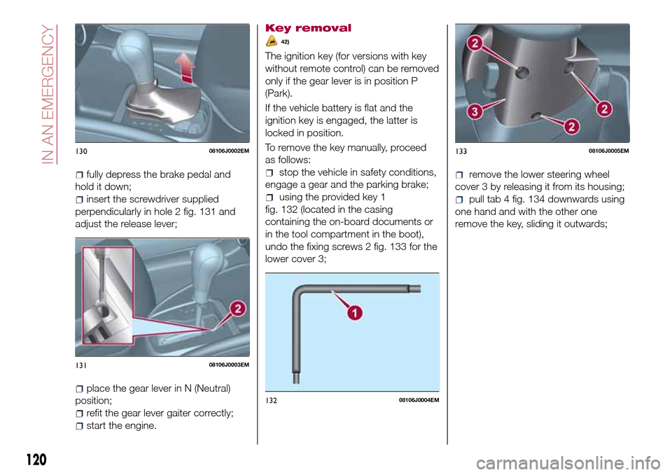
working carefully in the point
indicated by the arrow, remove the gear
lever gaiter 1 fig. 129 (also see
fig. 130 );
12908106J0001EM
119
Page 122 of 204

fully depress the brake pedal and
hold it down;
insert the screwdriver supplied
perpendicularly in hole 2 fig. 131 and
adjust the release lever;
place the gear lever in N (Neutral)
position;
refit the gear lever gaiter correctly;
start the engine.
Key removal
42)
The ignition key (for versions with key
without remote control) can be removed
only if the gear lever is in position P
(Park).
If the vehicle battery is flat and the
ignition key is engaged, the latter is
locked in position.
To remove the key manually, proceed
as follows:
stop the vehicle in safety conditions,
engage a gear and the parking brake;
using the provided key 1
fig. 132 (located in the casing
containing the on-board documents or
in the tool compartment in the boot),
undo the fixing screws 2 fig. 133 for the
lower cover 3;
remove the lower steering wheel
cover 3 by releasing it from its housing;
pull tab 4 fig. 134 downwards using
one hand and with the other one
remove the key, sliding it outwards;
13008106J0002EM
13108106J0003EM
13208106J0004EM
13308106J0005EM
120
IN AN EMERGENCY
Page 200 of 204

Interior lights................22
Interiors (cleaning)............146
ISOFIX child restraint system
(installation)...............71
iTPMS (indirect Tyre Pressure
Monitoring System)..........60
Jump starting..............117
Key removal (automatic
transmission).............120
Keys
key with remote control........9
Lever release (automatic
transmission).............119
Lifting the vehicle.............143
Light bulbs
types of bulbs............100
Luggage compartment
(extension)................14
Main beam headlights..........21
Main beam headlights (changing
a bulb)..................102
Main menu...............39,40
Manual climate control..........26
Manual gearbox..............86
Multifunction display...........36
Number plate lights (bulb
replacement)..............105
Occupant protection systems.....62
Paintwork (cleaning and
maintenance).............144Parking Brake...............85
Parking lights................20
Parking sensors..............91
Passenger compartment air
diffusers.................25
PBA (system)................58
Performance (top speed)........162
Periodic checks (scheduled
servicing)................131
Pre-tensioners...............65
Load limiters..............65
Prescriptions for handling the
vehicle at the end of its life.....166
Rain sensor................24
Rear current socket............34
Rear direction indicators (bulb
replacement)..............104
Rear seats..................14
Rear side lights (bulb
replacement)..............104
Rear view camera.............94
Rear View Camera............94
Rear view mirrors.............18
Reconfigurable Multifunction
Display..................37
Refuelling.................157
Refuelling procedure...........96
Emergency refuelling.........96
Refuelling the vehicle...........96
Replacing a bulb..............99Replacing an external bulb......102
Rims and tyres (dimensions)......152
SBR (Seat Belt Reminder).......64
SBR (Seat Belt Reminder) system.......................64
Scheduled servicing...........124
Scheduled Servicing Plan.......125
Screen wiper/washer...........23
Smart washing function.......23
Seat belts..................62
Seats.....................13
Servicing procedures..........140
Side bag...................80
Side direction indicators (bulb
replacement)..............103
Snow chains...............143
SRS (supplementary restraint
system)..................77
Starting the engine............84
Steering lock................10
Steering wheel...............17
Stop/Start system.............89
Symbols....................2
TC (system)................58
Technical data..............149
The keys...................9
Third brake light (bulb
replacement)..............105
Towing the vehicle............121
Towing trailers...............95
INDEX