2016 FIAT GRANDE PUNTO ACTUAL start stop button
[x] Cancel search: start stop buttonPage 62 of 216

61
SAFETY
STARTING
AND DRIVING
WARNING
LIGHTS AND
MESSAGES
IN AN
EMERGENCY
SERVICE
AND CARE
TECHNICAL
SPECIFICATIONS
INDEX
CONTROLS
AND DEVICES
ANTI-PINCH SAFETY SYSTEM
The sunroof has an anti-pinch safety sys-
tem capable of detecting the presence of
an obstacle whilst the roof is closing; when
this happens, the system stops and the
movement of the glass is immediately re-
versed.INITIALISATION PROCEDURE
The sunroof must be re-initialised after
disconnecting the battery or if the rele-
vant protection fuse is blown.
Proceed as follows:
❒press button A-fig. 67at close posi-
tion;
❒hold the button down so that the sun-
roof closes in stages;
❒after full closing, wait for sunroof’s elec-
tric motor to stop.
When leaving the car, always remove the
key from the ignition to avoid the risk of
injury due to accidental operation of the
sunroof. Improper use of the roof can be
dangerous. Before and during operation,
always check that no-one is exposed to
the risk of being injured by the moving
sunroof or by objects getting caught and
dragged by it.EMERGENCY OPERATION
If the switch fails, the sun roof can be
moved manually as follows:
❒remove the protection cap located
between the two shutters;
❒take the Allen key (provided as stan-
dard) from the toolbox in the boot;
❒insert the key into hole A-fig. 69and
turn it:
– clockwise to open the roof;
– anticlockwise to close the roof.
fig. 69F0M0088m
033-071 ACTUAL 1ed EN 18-01-2011 11:49 Pagina 61
Page 66 of 216

65
SAFETY
STARTING
AND DRIVING
WARNING
LIGHTS AND
MESSAGES
IN AN
EMERGENCY
SERVICE
AND CARE
TECHNICAL
SPECIFICATIONS
INDEX
CONTROLS
AND DEVICES
WINDOWS
ELECTRIC
Two switches fig. 75on the armrest in-
side the driver’s door control the follow-
ing with the ignition key turned to MAR:
Aopening/closing of the left front window;
B opening/closing the right front window.Keep one of the buttons pressed for
longer than half a secondto operate
the automatic continuous operation of the
window. The window will stop when it is
fully opened or closed, or when the but-
ton is pressed again.
IMPORTANT In the event that the anti-
crushing function is activated 5 times in
only 1 minute, the system will automati-
cally enter the “recovery” mode (self-pro-
tection). This condition is apparent from
the window closing in stages.
fig. 75F0M0136m
Continuous automatic operation
The car has an automatic setting to raise
and lower the driver-side front window.
033-071 ACTUAL 1ed EN 21-07-2010 14:26 Pagina 65
Page 67 of 216

66
SAFETY
STARTING
AND DRIVING
WARNING
LIGHTS AND
MESSAGES
IN AN
EMERGENCY
SERVICE
AND CARE
TECHNICAL
SPECIFICATIONS
INDEX
CONTROLS
AND DEVICES
Electric window system
initialisation
The system must be re-initialised after dis-
connecting the battery or if the relevant
protection fuse is blown.
Initialisation procedure:
❒fully close the window to be initialised
manually;
❒once fully closed, keep holding down the
closing control for at least 1 second.
Improper use of the electric
windows can be dangerous.
Before and during operation, always
check that no-one is exposed to the
risk of being injured either directly by
the moving window or through objects
getting caught and being dragged by
it. When leaving the vehicle, always
remove the key from the ignition to
avoid the risk of injury to anyone re-
maining in the car due to accidental
operation of the electric windows.
WARNING
MANUAL REAR WINDOWS
(5-door versions) fig. 76
To open and to close the window, use the
relevant handle.
fig. 76F0M0091m
On such occasions, it is necessary to car-
ry out the system restore procedure,
acting as follows:
❒ open the windows;
or
❒turn the ignition key to STOPand then
to MAR.
If no malfunction is present, the window
returns to its normal operation auto-
matically.
IMPORTANT With the ignition key at
STOPor removed, the windows remain
activated for about 2 minutes and are de-
activated as soon a door is opened.
The system conforms to the
2000/4/EC standard concern-
ing the safety of passengers leaning
out of the passenger compartment.
WARNING
IMPORTANT On some versions, press-
ing the remote control button Ëfor over
2 seconds will open the windows, where-
as pressing the remote control button
Áfor over 2 seconds will close them.
033-071 ACTUAL 1ed EN 21-07-2010 14:26 Pagina 66
Page 83 of 216

82
SAFETY
STARTING
AND DRIVING
WARNING
LIGHTS AND
MESSAGES
IN AN
EMERGENCY
SERVICE
AND CARE
TECHNICAL
SPECIFICATIONS
INDEX
CONTROLS
AND DEVICES
fig. 100F0M0506mfig. 101F0M0507m
MANUAL ACTIVATION AND
DEACTIVATION
You can activate/deactivate the device
by pressing the button on the dashboard
fig. 101. When the system is switched off,
“Start&Stop OFF” appears on the dash-
boardfig. 100.
In addition, (for versions/markets, where
provided) additional indications concern-
ing the deactivation or activation of
Start&Stop is given through a message on
the display.NO ENGINE CUT-OUT
CONDITIONS
With the device activated, for reasons of
comfort, limiting emissions and safety, the
engine does not stop in certain conditions,
including:
❒engine still cold;
❒particularly cold external temperatures,
where the appropriate indication is pro-
vided;
❒battery not sufficiently charged;
❒heated rear windscreen activated;
❒windscreen wipers working at maxi-
mum speed;
❒diesel particulate filter (DPF) regener-
ation ongoing (for versions/markets,
where provided);
❒driver’s door not shut;
❒driver’s seat belt not fastened;
❒reverse gear engaged (for example, dur-
ing parking manoeuvres);
❒automatic climate control, if a com-
fortable temperature has not yet been
reached or MAX – DEF function en-
abled;
❒during the first period of use, to initial-
ize the system.
In the above cases, an information mes-
sage appears on the display and (for ver-
sions/markets, where provided) the warn-
ing lightfig. 99will flash on the instrument
panel.
072-092 ACTUAL 1ed EN 26-07-2010 10:55 Pagina 82
Page 85 of 216

84
SAFETY
STARTING
AND DRIVING
WARNING
LIGHTS AND
MESSAGES
IN AN
EMERGENCY
SERVICE
AND CARE
TECHNICAL
SPECIFICATIONS
INDEX
CONTROLS
AND DEVICES
CAR INACTIVITY fig. 103
(with Start&Stop system with
dummy pole)
(for versions/markets where provided)
In case of vehicle inactivity conditions, pay
special attention to the disconnection of
the battery power supply. The procedure
must be made by disconnecting the quick
release negative terminalA-fig. 103from
the dummy negative poleB,asthebattery
negative poleChas a sensorDfor bat-
tery condition monitoring that must nev-
er be disconnected (unless the battery is
replaced).CAR INACTIVITY fig. 104
(with Start&Stop system without
dummy pole)
(for versions/markets where provided)
In case of car inactivity, special attention
must be paid due to the disconnection of
the battery power supply. Proceed as fol-
lows: detach the connectorA-fig. 104(by
pressing buttonB) from sensorCfor
monitoring the battery status installed on
the battery negative poleD. This sensor
should never be disconnected from the
pole except if the battery is replaced.EMERGENCY STARTING
(with Start&Stop system with
dummy pole)
(for versions/markets where provided)
In case of vehicle jump starting, never
connect the negative cable (–) of the
auxiliary battery to the negative pole
B-fig. 105of the vehicle battery, rather
to the dummy pole A or to an en-
gine/gearbox earth point.
When replacing the battery,
always go to a Fiat Dealer-
ship. Replace the battery using a new
one of the same type (HEAVY DUTY)
and having the same specifications.
WARNING
fig. 103F0M0514mfig. 104F0M0516mfig. 105F0M0517m
072-092 ACTUAL 1ed EN 26-07-2010 10:55 Pagina 84
Page 116 of 216

115
SAFETY
WARNING
LIGHTS AND
MESSAGES
IN AN
EMERGENCY
SERVICE
AND CARE
TECHNICAL
SPECIFICATIONS
INDEX
CONTROLS
AND DEVICES
STARTING
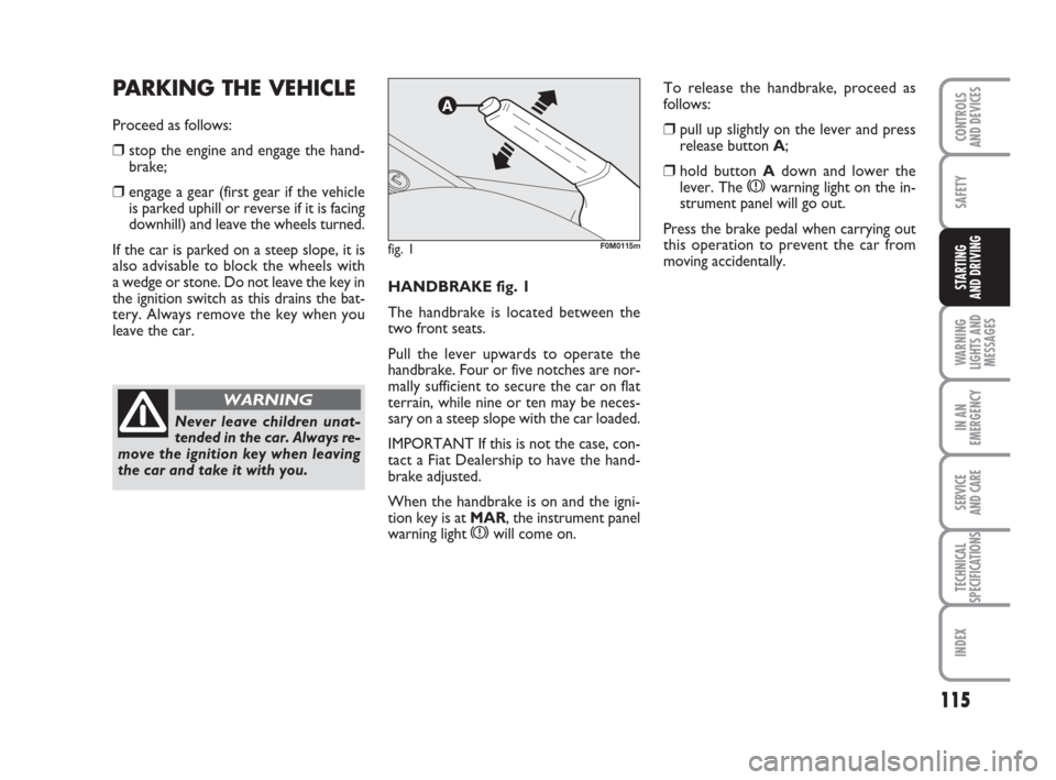
AND DRIVINGHANDBRAKE fig. 1
The handbrake is located between the
two front seats.
Pull the lever upwards to operate the
handbrake. Four or five notches are nor-
mally sufficient to secure the car on flat
terrain, while nine or ten may be neces-
sary on a steep slope with the car loaded.
IMPORTANT If this is not the case, con-
tact a Fiat Dealership to have the hand-
brake adjusted.
When the handbrake is on and the igni-
tion key is at MAR, the instrument panel
warning light
xwill come on.
PARKING THE VEHICLE
Proceed as follows:
❒stop the engine and engage the hand-
brake;
❒engage a gear (first gear if the vehicle
is parked uphill or reverse if it is facing
downhill) and leave the wheels turned.
If the car is parked on a steep slope, it is
also advisable to block the wheels with
a wedge or stone. Do not leave the key in
the ignition switch as this drains the bat-
tery. Always remove the key when you
leave the car.
Never leave children unat-
tended in the car. Always re-
move the ignition key when leaving
the car and take it with you.
WARNING
fig. 1F0M0115m
To release the handbrake, proceed as
follows:
❒pull up slightly on the lever and press
release button A;
❒hold button Adown and lower the
lever. The xwarning light on the in-
strument panel will go out.
Press the brake pedal when carrying out
this operation to prevent the car from
moving accidentally.
111-122 ACTUAL 1ed EN 20-07-2010 16:10 Pagina 115
Page 165 of 216

164
SAFETY
STARTING
AND DRIVING
WARNING
LIGHTS AND
MESSAGES
SERVICE
AND CARE
TECHNICAL
SPECIFICATIONS
INDEX
CONTROLS
AND DEVICES
IN AN
EMERGENCY
RAISING THE CAR
If the car needs to be lifted, go to a Fiat
Dealership which is equipped with the arm
hoist or workshop lift.
The car should be lifted side-on only, by
putting the ends of the arms or the work-
shop lifting device in the areas shown in
the diagram.
Do not try to rechargea frozen
battery; defrost it first to pre-
vent the risk of explosion. If the bat-
tery was frozen, have it inspected by
specialised personnel before recharg-
ing to check that the internal ele-
ments are not damaged and that the
casing is not cracked, which could
cause poisonous, corrosive gas to leak.
WARNING
fig. 42F0M0513m
Battery fluid is poisonous
and corrosive: avoid contact
with your skin and eyes. The battery
must be recharged in a ventilated
place away from naked flames or
possible sources of sparks to avoid the
risk of explosion and fire.
WARNING
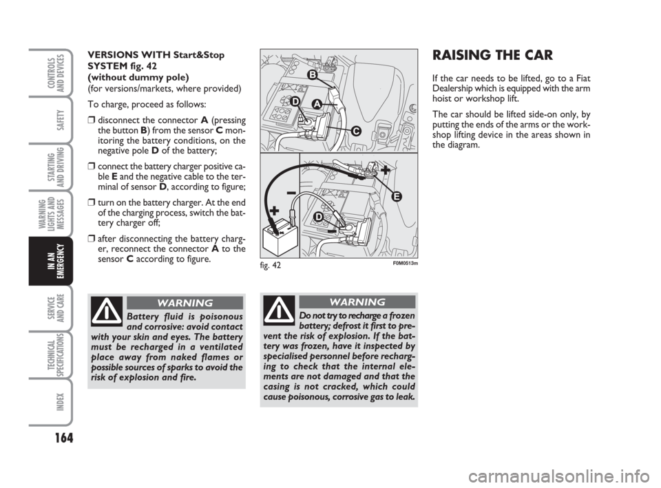
VERSIONS WITH Start&Stop
SYSTEM fig. 42
(without dummy pole)
(for versions/markets, where provided)
To charge, proceed as follows:
❒disconnect the connector A(pressing
the button B) from the sensor Cmon-
itoring the battery conditions, on the
negative pole Dof the battery;
❒connect the battery charger positive ca-
ble Eand the negative cable to the ter-
minal of sensor D, according to figure;
❒turn on the battery charger. At the end
of the charging process, switch the bat-
tery charger off;
❒after disconnecting the battery charg-
er, reconnect the connector Ato the
sensor Caccording to figure.
135-166 ACTUAL 1ed EN 26-07-2010 16:00 Pagina 164