2016 FIAT FREEMONT mirror
[x] Cancel search: mirrorPage 111 of 412

Using Electronic Speed Control On Hills
The transmission may downshift on hills to maintain
the vehicle set speed.
NOTE:The Electronic Speed Control system main-
tains speed up and down hills. A slight speed change on
moderate hills is normal.
On steep hills, a greater speed loss or gain may occur
so it may be preferable to drive without Electronic
Speed Control.
WARNING!
Electronic Speed Control can be danger-
ous w h
ere the system cannot maintain a
constant speed.Your vehicle could go too fast for
the conditions, and you could lose control and
have an accident . Do not use Electronic Speed
Control in heavy traffic or on roads that are
winding, icy, snow-covered or slippery.
OVERHEAD CONSOLE
The overhead console contains courtesy/reading lights,
storage for sunglasses, an interior observation mirror
and an optional power sunroof switch.
(fig. 68)
(fig. 68)
Overhead Console
105
KNOWING
YOUR
VEHICLE
SAFETY
STAR
TING
AND
DRIVING
WARNING
LIGHTS
AND
MESSAGES
IN AN
EMERGENCY
SERVICING
AND CARE
TECHNICAL
SPECIFICATIONS
CONTENTS
Page 112 of 412

COURTESY/READING LIGHTS
The overhead console has two courtesy lights. The
lights turn on when a door or the liftgate is opened. If
your vehicle is equipped with Remote Keyless Entry
(RKE) the lights will also turn on when the UNLOCK
button on the RKE transmitter is pressed. The cour-
tesy lights also function as reading lights. Press in on
each lens to turn these lights on while inside the
vehicle. Press the lens a second time to turn each light
off. You may adjust the direction of these lights by
pressing the outside ring, which is identified with four
directional arrows.
(fig. 69)
SUNGLASSES STORAGE
To access the storage compartment, press on the
raised bars on the compartment door in the center of
the console and release and the door will swing
downward.
(fig. 70)
INTERIOR OBSERVATION MIRROR
The convex interior observation mirror provides the
driver and front seat passenger a wide field of view to
conveniently view passengers sitting in the rear passen-
ger seats. To use the interior observation mirror, press
on the raised bars on the compartment door and
release (the door will swing downward), then raise the
door until it is almost closed and release. The door will
latch in position to use the interior observation mirror.
(fig. 69)Courtesy/Reading Light(fig. 70)Sunglasses Storage Compartment
106
KNOWINGYOUR
VEHICLE
SAFETY
STAR
TINGAND
DRIVING
WARNING LIGHTSAND
MESSAGES
IN AN
EMERGENCY
SERVICINGAND CARE
TECHNICAL
SPECIFICATIONS
CONTENTS
Page 113 of 412

NOTE:From the “observation mirror” position, the
door can only be closed.
To return to the full open position, the door must first
be closed and then opened by pressing the latch again
to release.
(fig. 71)
POWER SUNROOF SWITCH (for
versions/markets, where provided)
Refer to “Power Sunroof ” for further information.
HAZARD WARNING FLASHERS
The Hazard Warning flasher switch is located in the
instrument panel switch bank, above the climate
controls.
Press the switch to turn on the Hazard Warning
flasher. When the switch is activated, all direc-
tional turn signals will flash on and off to warn oncom-
ing traffic of an emergency. Press the switch a second
time to turn off the Hazard Warning flashers.
This is an emergency warning system and it should not
be used when the vehicle is in motion. Use it when your
vehicle is disabled and it is creating a safety hazard for
other motorists.
When you must leave the vehicle to seek assistance,
the Hazard Warning flashers will continue to operate
even though the ignition is placed in the OFF position.
NOTE: With extended use the Hazard Warning flash-
ers may wear down your battery.
(fig. 71)
Observation Mirror
107
KNOWING
YOUR
VEHICLE
SAFETY
STAR
TING
AND
DRIVING
WARNING
LIGHTS
AND
MESSAGES
IN AN
EMERGENCY
SERVICING
AND CARE
TECHNICAL
SPECIFICATIONS
CONTENTS
Page 243 of 412

STARTING AND DRIVING
ENGINE BREAK-IN
RECOMMENDATIONS
A long break-in period is not required for the engine
and drivetrain (transmission and axle) in your vehicle.
Drive moderately during the first 500 km. After the
initial 100 km, speeds up to 80 or 90 km/h are desirable.
While cruising, brief full-throttle acceleration, within
the limits of local traffic laws contributes to a good
break-in. Wide-open throttle acceleration in low gear
can be detrimental and should be avoided.
The engine oil installed in the engine at the factory is a
high-quality energy-conserving type lubricant. Oil
changes should be consistent with anticipated climate
conditions under which vehicle operations will occur.
For the recommended viscosity and quality grades,
refer to “Maintenance Procedures” in “Servicing And
Care”. NON-DETERGENT OR STRAIGHT MINERAL
OILS MUST NEVER BE USED.
A new engine may consume some oil during its first few
thousand kilometers of operation. This should be con-
sidered a normal part of the break-in and not inter-
preted as an indication of difficulty.
STARTING PROCEDURES
Before starting your vehicle, adjust your seat, adjust the
inside and outside mirrors, fasten your seat belt, and if
present, instruct all other occupants to buckle their
seat belts.
WARNING!
• Before exiting a vehicle, always apply
t h
e parking brake, shift the transmission
into PARK, and remove the Key Fob from the
ignition. When leaving the vehicle, always lock
your vehicle.
• Never leave children alone in a vehicle, or with
access to an unlocked vehicle.
• Allowing children to be in a vehicle unattended
is dangerous for a number of reasons. A child or
others could be seriously or fatally injured. Chil-
dren should be warned not to touch the parking
brake, brake pedal or the shift lever.
(Continued)
237
KNOWING
YOUR
VEHICLE
SAFETY
STARTING
AND
DRIVING
WARNING
LIGHTS
AND
MESSAGES
INAN
EMERGENC
Y
SERVICING
AND CARE
TECHNICAL
SPECIFICATIONS
CONTENTS
Page 275 of 412

Cooling System
To reduce potential for engine and transmission over-
heating, take the following actions:
City Driving
When stopped for short periods, shift the transmission
into NEUTRAL and increase engine idle speed.
Highway Driving
Reduce speed.
Air Conditioning
Turn off temporarily.
TRAILER HITCH ATTACHING POINTS
Your vehicle will require extra equipment to tow a
trailer safely and efficiently. The trailer tow hitch must
be attached to your vehicle using the provided attach-
ing points on the vehicle's frame. Refer to the following
chart to determine the accurate attaching points.
Other equipment, such as trailer sway controls and
braking equipment, trailer equalizing (leveling) equip-
ment and low profile mirrors, may also be required or
strongly recommended.
(fig. 165)
Trailer Tow Hitch Attaching Points And OverhangDimensions
A N/A
B 366.71 mm
C 501.62 mm
D 628.69 mm
E (maximum overhang) 1051.93 mm
F 472.00 mm
(fig. 165)
269
KNOWING
YOUR
VEHICLE
SAFETY
STARTING
AND
DRIVING
WARNING
LIGHTS
AND
MESSAGES
IN AN
EMERGENC
Y
SERVICING
AND CARE
TECHNICAL
SPECIFICATIONS
CONTENTS
Page 314 of 412

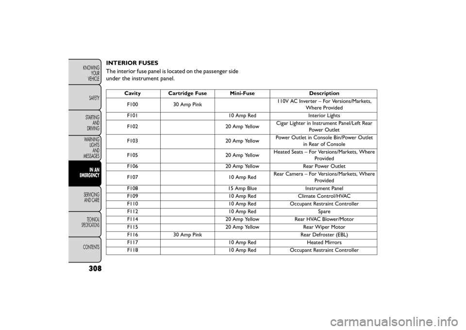
INTERIOR FUSES
The interior fuse panel is located on the passenger side
under the instrument panel.
CavityCartridge Fuse Mini-Fuse Description
F100 30 Amp Pink 110V AC Inverter – For Versions/Markets,
Where Provided
F101 10 Amp RedInterior Lights
F102 20 Amp YellowCigar Lighter in Instrument Panel/Left Rear
Power Outlet
F103 20 Amp YellowPower Outlet in Console Bin/Power Outlet
in Rear of Console
F105 20 Amp YellowHeated Seats – For Versions/Markets, Where
Provided
F106 20 Amp YellowRear Power Outlet
F107 10 Amp RedRear Camera – For Versions/Markets, Where
Provided
F108 15 Amp BlueInstrument Panel
F109 10 Amp RedClimate Control/HVAC
F110 10 Amp RedOccupant Restraint Controller
F112 10 Amp RedSpare
F114 20 Amp YellowRear HVAC Blower/Motor
F115 20 Amp YellowRear Wiper Motor
F116 30 Amp Pink Rear Defroster (EBL)
F117 10 Amp RedHeated Mirrors
F118 10 Amp RedOccupant Restraint Controller
308
KNOWING
YOUR
VEHICLE
SAFETY
STARTING AND
DRIVING
WARNING LIGHTSAND
MESSAGES
IN AN
EMERGENCY
SER VICING
AND
CARE
TECHNICAL
SPECIFICATIONS
CONTENTS
Page 315 of 412

CavityCartridge Fuse Mini-Fuse Description
F119 10 Amp RedSteering Column Control Module
F120 10 Amp RedAll Wheel Drive – For Versions/Markets,
Where Provided
F121 15 Amp BlueWireless Ignition Node
F122 25 Amp ClearDriver Door Module
F123 25 Amp ClearPassenger Door Module
F124 10 Amp RedMirrors
F125 10 Amp RedSteering Column Control Module
F126 10 Amp RedAudio Amplifier
F127 20 Amp YellowTrailer Tow – For Versions/Markets, Where
Provided
F128 15 Amp BlueRadio
F129 15 Amp BlueVideo/DVD – For Versions/Markets, Where
Provided
F130 15 Amp BlueClimate Control/Instrument Panel
F131 10 Amp RedPassenger Assistance/Hands Free System –
For Versions/Markets, Where Provided
F132 10 Amp RedTire Pressure Module
F133 10 Amp RedSpare
309
KNOWING
YOUR
VEHICLE
SAFETY
STARTING
AND
DRIVING
WARNING
LIGHTS
AND
MESSAGES
IN AN
EMERGENCY
SERVICING
AND
CARE
TECHNICAL
SPECIFICATIONS
CONTENTS
Page 364 of 412

Glass Surfaces
All glass surfaces should be cleaned on a regular basis
with any commercial household-type glass cleaner.
Never use an abrasive type cleaner. Use caution when
cleaning the inside rear window equipped with an
electric defroster. Do not use scrapers or other sharp
instruments that may scratch the elements.
When cleaning the rear view mirror, spray cleaner on
the towel or rag that you are using. Do not spray
cleaner directly on the mirror.
Cleaning Plastic Instrument Cluster Lenses
The lenses in front of the instruments in this vehicle are
molded in clear plastic. When cleaning the lenses, care
must be taken to avoid scratching the plastic.
1. Clean with a wet soft rag. A mild soap solution maybe used, but do not use high alcohol content or
abrasive cleaners. If soap is used, wipe clean with a
clean damp rag.
2. Dry with a soft cloth. Seat Belt Maintenance
Do not bleach, dye or clean the belts with chemical
solvents or abrasive cleaners. This will weaken the
fabric. Sun damage can also weaken the fabric.
If the belts need cleaning, use a mild soap solution or
lukewarm water. Do not remove the belts from the car
to wash them. Dry with a soft cloth.
Replace the belts if they appear frayed or worn or if the
buckles do not work properly.
WARNING!
A frayed or torn belt could rip apart in a
collisi on
and leave you with no protec-
tion. Inspect the belt system periodically, check-
ing for cuts, frays, or loose parts. Damaged parts
must be replaced immediately. Do not disas-
semble or modify the system. Seat belt assem-
blies must be replaced after a collision if they
have been damaged (i.e., bent retractor, torn
webbing, etc .).
CLEANING THE CUP HOLDERS
Clean with a damp cloth or towel using a mild deter-
gent.
358
KNOWING YOUR
VEHICLE
SAFETY
STARTING AND
DRIVING
WARNING LIGHTSAND
MESSAGES
IN AN
EMERGENCY
SERVICINGAND C ARE
TECHNICAL
SPECIFICATIONS
CONTENTS