2016 FIAT DUCATO plate
[x] Cancel search: platePage 138 of 296

In addition to the electrical branches,
the vehicle's electric system can only
be connected to the supply cable for an
electric brake and to the cable for an
internal light, though not above 15
W. For connections use the preset
control unit with battery cable no less
than 2.5 mm
2.
IMPORTANT The trailer tow hook
contributes to the length of the vehicle.
When installing on long wheelbase
versions, it is only possible to install
removable tow hooks because the total
vehicle length limit of 6 metres is
exceeded.
If no trailer is fitted, the hook must be
removed from the attachment base and
it must not exceed the vehicle's
original length.
IMPORTANT If you wish to leave the
tow hook fitted without towing a trailer,
it is advisable to contact a Fiat
Dealership for the relevant system
update operations because the tow
hook could be detected as an obstacle
by the central sensors.Installation diagram for Van
versions fig. 121
The tow hook structure must be
fastened in the points shown by the
symbol Ø using a total of 6 M10x1.25
screws and 4 M12 screws.
The internal back plates must be at
least 5 mm thick. MAX LOAD ON
BALL: 100/120 kg depending on the
payload (see the “Weights” table in the
“Technical Data” chapter).
138)
To install a tow hook, the bumpers
must be trimmed as described in the
supplier's installation kit.
Installation diagram for Truck and
Chassis Cab versions fig. 122
Another tow hook specific to Truck and
Chassis Cab versions is shown in fig.
122.
The structure Ø must be fixed in the
points indicated using a total of 6
M10x1.25 screws and 4 M12 screws.MAX LOAD ON BALL: 100/120 kg
depending on the payload (see the
“Weights” table in the “Technical Data”
chapter).
WARNING
136)The ABS with which the vehicle may
be equipped will not control the braking
system of the trailer. Particular caution
is required on slippery roads.
137)Never modify the braking system of
the vehicle to control the trailer brake. The
trailer braking system must be fully
independent from the hydraulic system of
the vehicle.
138)After fitting, screw holes must be
sealed to prevent a exhaust gas inlet.
.
136
STARTING AND DRIVING
Page 141 of 296

INSTRUCTIONS FOR
USING THE REMOVABLE
BALL HEAD TOW BAR
40) 41) 42) 43) 44) 45)Before setting off, check the correct
locking of the removable ball head tow
bar, as follows:
The green mark of the flywheel must
coincide with the green mark on the
tow bar.
The flywheel is in the stop position
on the tow bar (without slot).
Locked lock and key removed. The
flywheel cannot be removed.
Ball head bar firmly secured to the
housing pipe. Check by shaking with a
hand.
The fitting procedure must be repeated
if any of the 4 checked requirements
is not met.
If even only one of the requirements is
not met the tow hook must not be
used, as in this case there is risk of
accidents. Contact the joint
manufacturer.
The ball head tow bar can be fitted and
removed manually, without needing
any tool.
Never use working tools or means, as
the mechanism could be damaged.
Never unlock in the case of trailer
attached to the vehicle or fitted rack.When driving without trailer or rack the
ball head tow bar must be removed
and the closing plug must always
be inserted in the housing pipe. This
applies particularly if the visibility of the
number plate characters or of the
lighting system is reduced.
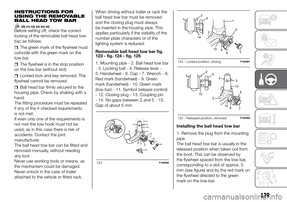
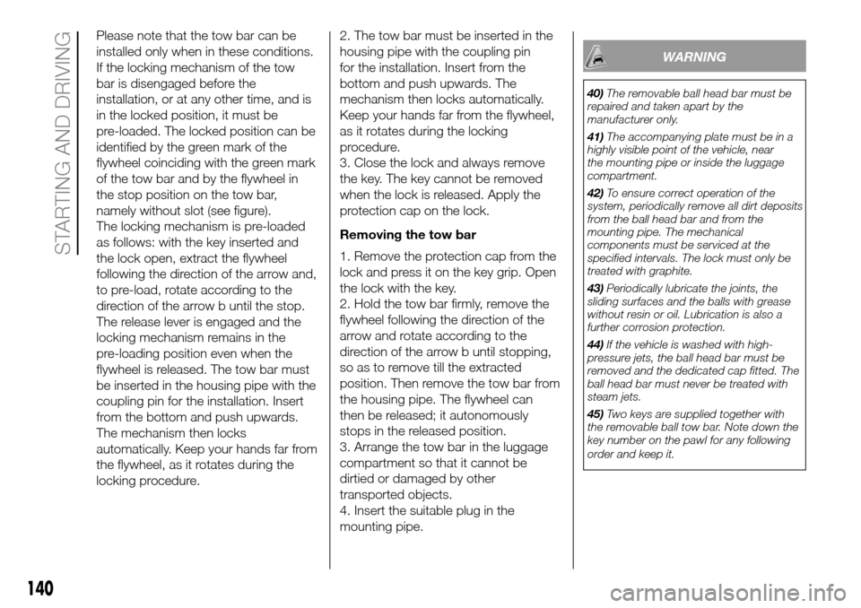
Removable ball head tow bar fig.
123 - fig. 124 - fig. 125
1. Mounting pipe - 2. Ball head tow bar
- 3. Locking ball - 4. Release lever -
5. Handwheel - 6. Cap - 7. Wrench - 8.
Red mark (handwheel) - 9. Green
mark (handwheel) - 10. Green mark
(tow bar) - 11. Symbol (release control)
- 12. Closing plug - 13. Coupling pin
- 14. No gaps between 2 and5-15.
Gap of about 5 mm
Installing the ball head tow bar
1. Remove the plug from the mounting
pipe.
The ball head tow bar is usually in the
released position when taken out from
the boot. This can be observed by
the flywheel spaced from the tow bar,
corresponding to a slot of approx. 5
mm (see figure) and by the red mark on
the flywheel directed to the green
mark on the tow bar.
123F1A0380
124 - Locked position, drivingF1A0381
125 - Released position, removedF1A0382
139
Page 142 of 296

Please note that the tow bar can be
installed only when in these conditions.
If the locking mechanism of the tow
bar is disengaged before the
installation, or at any other time, and is
in the locked position, it must be
pre-loaded. The locked position can be
identified by the green mark of the
flywheel coinciding with the green mark
of the tow bar and by the flywheel in
the stop position on the tow bar,
namely without slot (see figure).
The locking mechanism is pre-loaded
as follows: with the key inserted and
the lock open, extract the flywheel
following the direction of the arrow and,
to pre-load, rotate according to the
direction of the arrow b until the stop.
The release lever is engaged and the
locking mechanism remains in the
pre-loading position even when the
flywheel is released. The tow bar must
be inserted in the housing pipe with the
coupling pin for the installation. Insert
from the bottom and push upwards.
The mechanism then locks
automatically. Keep your hands far from
the flywheel, as it rotates during the
locking procedure.2. The tow bar must be inserted in the
housing pipe with the coupling pin
for the installation. Insert from the
bottom and push upwards. The
mechanism then locks automatically.
Keep your hands far from the flywheel,
as it rotates during the locking
procedure.
3. Close the lock and always remove
the key. The key cannot be removed
when the lock is released. Apply the
protection cap on the lock.
Removing the tow bar
1. Remove the protection cap from the
lock and press it on the key grip. Open
the lock with the key.
2. Hold the tow bar firmly, remove the
flywheel following the direction of the
arrow and rotate according to the
direction of the arrow b until stopping,
so as to remove till the extracted
position. Then remove the tow bar from
the housing pipe. The flywheel can
then be released; it autonomously
stops in the released position.
3. Arrange the tow bar in the luggage
compartment so that it cannot be
dirtied or damaged by other
transported objects.
4. Insert the suitable plug in the
mounting pipe.
WARNING
40)The removable ball head bar must be
repaired and taken apart by the
manufacturer only.
41)The accompanying plate must be in a
highly visible point of the vehicle, near
the mounting pipe or inside the luggage
compartment.
42)To ensure correct operation of the
system, periodically remove all dirt deposits
from the ball head bar and from the
mounting pipe. The mechanical
components must be serviced at the
specified intervals. The lock must only be
treated with graphite.
43)Periodically lubricate the joints, the
sliding surfaces and the balls with grease
without resin or oil. Lubrication is also a
further corrosion protection.
44)If the vehicle is washed with high-
pressure jets, the ball head bar must be
removed and the dedicated cap fitted. The
ball head bar must never be treated with
steam jets.
45)Two keys are supplied together with
the removable ball tow bar. Note down the
key number on the pawl for any following
order and keep it.
140
STARTING AND DRIVING
Page 147 of 296

Light bulbs
Light bulbs Type Power Figure ref.
Main beam headlights H7 55W D
Dipped beam headlights H7 55W D
Front side lights / daytime running lights
W21/5W - LED
(#)--
Front fog lights
(*)H11 55W -
Front direction indicators WY21W 21W B
Side turn lightW16WF
(**) / WY5W
(***)16W(**) / 5W (***)A
Rear direction indicators PY2IW 21W B
Side lights W5W 5W A
Rear side lights P21/5W 21/5W B
Rear side lights/Brake lights P21W 21W B
Third brake light W5W 5W B
Reverse gear W16W 16W B
Rear fog light W16W 16W B
Number plate C5W 5W A
Front roof light (movable lens) 12V10W 10W C
Rear ceiling light 12V10W 10W C
(#) where provided, instead of bulb W21/5W
(*)for versions/markets, where provided
(**)XL and Tempo Libero versions
(***)all other versions
145
Page 152 of 296

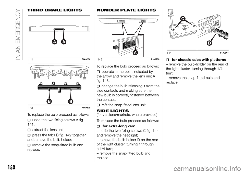
THIRD BRAKE LIGHTS
To replace the bulb proceed as follows:
undo the two fixing screws A fig.
141;
extract the lens unit;
press the tabs B fig. 142 together
and remove the bulb holder;
remove the snap-fitted bulb and
replace.NUMBER PLATE LIGHTS
To replace the bulb proceed as follows:
operate in the point indicated by
the arrow and remove the lens unit A
fig. 143;
change the bulb releasing it from the
side contacts and making sure the
new bulb is correctly fastened between
the contacts;
refit the snap-fitted lens unit.
SIDE LIGHTS
(for versions/markets, where provided)
To replace the bulb proceed as follows:
for extra-long van:
– undo the two fixing screws C fig. 144
and remove the headlight;
– remove the bulb holder D on the rear
of the light cluster, turning it through
a 1/4 turn;
– remove the snap-fitted bulb and
replace.
for chassis cabs with platform:
– remove the bulb-holder on the rear of
the light cluster, turning through 1/4
turn;
– remove the snap-fitted bulb and
replace.141F1A0204
142F1A0205
143F1A0206
144F1A0207
150
IN AN EMERGENCY
Page 207 of 296

WARNING
57)Keep your speed down when snow
chains are fitted; do not exceed 50 km/h.
Avoid potholes, steps and pavements
and avoid driving for long distances on
roads not covered with snow to prevent
damaging the vehicle and the roadbed.
BODYWORK
PROTECTION AGAINST
ATMOSPHERIC AGENTS
The main causes of corrosion are the
following:
atmospheric pollution;
salty air and humidity (coastal areas,
or hot humid climates);
seasonal environmental conditions.
ADVICE FOR
PRESERVING THE
BODYWORK
Paintwork
Paintwork does not only serve an
aesthetic purpose, but also protects the
underlying sheet metal.
Touch up abrasions and scratches
immediately to prevent rust formation.
Use only original paint products for
touch-ups (see “Bodywork paint
identification plate” in the “Technical
specifications” section).
Normal maintenance of paintwork
consists in washing the car: the
frequency depends on the conditions
and environment where the car is used.
For example, it is advisable to wash
the vehicle more often in areas with
high levels of environmental pollution or
on roads spread with salt.To correctly wash the vehicle, proceed
as follows:
wash the bodywork using a low
pressure jet of water;
wipe a sponge with a slightly soapy
solution over the bodywork, frequently
rinsing the sponge;
rinse well with water and dry with a
jet of air or a chamois leather.
If you put the vehicle through a car
wash, follow these recommendations:
remove the aerial from the roof
so it does not get damaged;
the vehicle should be washed with
water added to a soapy solution;
rinse thoroughly to avoid soap
marks remaining on the bodywork or
less visible parts.
58)
6)
WARNING
58)Some automatic systems equipped
with old generation blades and/or with
a poor maintenance can damage the paint,
promoting the creation of microscoring
which give an opaque/coated appearance
to the paint, especially on dark colours.
In this case, just lightly polish with specific
products.
205
Page 211 of 296

IDENTIFICATION
DATA
It is advisable to take note of the
identification codes. Identification codes
are printed and shown on the plates
as indicated below, together with the
positions:
VIN plate.
Chassis marking.
Bodywork paint identification plate.
Engine marking.
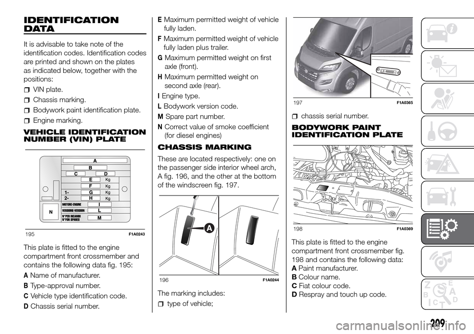
VEHICLE IDENTIFICATION
NUMBER (VIN) PLATE
This plate is fitted to the engine
compartment front crossmember and
contains the following data fig. 195:
AName of manufacturer.
BType-approval number.
CVehicle type identification code.
DChassis serial number.
EMaximum permitted weight of vehicle
fully laden.
FMaximum permitted weight of vehicle
fully laden plus trailer.
GMaximum permitted weight on first
axle (front).
HMaximum permitted weight on
second axle (rear).
IEngine type.
LBodywork version code.
MSpare part number.
NCorrect value of smoke coefficient
(for diesel engines)
CHASSIS MARKING
These are located respectively: one on
the passenger side interior wheel arch,
A fig. 196, and the other at the bottom
of the windscreen fig. 197.
The marking includes:
type of vehicle;
chassis serial number.
BODYWORK PAINT
IDENTIFICATION PLATE
This plate is fitted to the engine
compartment front crossmember fig.
198 and contains the following data:
APaint manufacturer.
BColour name.
CFiat colour code.
DRespray and touch up code.
195F1A0243
196F1A0244
197F1A0365
198F1A0369
209
Page 212 of 296

ENGINE MARKING
It is stamped on the cylinder block and
includes the type and the engine serial
number.
CYLINDER MARKING
Each methane cylinder is identified in
the factory with a stamp on the nose of
the cylinder.
The other plates provided by the
Dealership with the vehicle documents
show the date when the first cylinder
inspection/test is due.
59)
SYSTEM INSPECTION
The cylinders must be inspected, in
accordance with ECE Regulation
Procedure no. 110, every 4 years from
the vehicle registration date or in
accordance with specific regulations in
individual countries.
WARNING
59)If the vehicle has been registered in a
country other than Italy, the certification
data, identification and inspection
procedures for the methane cylinders
should conform to the legislation in that
country. In any case, it should be
remembered that the life of the cylinders is
20 years from the production date as set
out in ECE Regulation no. 110.
199F0N0405M
210
TECHNICAL DATA