2016 FIAT DUCATO High pressure
[x] Cancel search: High pressurePage 126 of 296

WARNING
123)The responsibility for parking and
other manoeuvres is always and in any
case charged to the driver. While carrying
out these manoeuvres, always make
sure that no people (especially children) or
animals are in the area concerned. The
camera is an aid for the driver, but the
driver must never allow his/her attention to
lapse during potentially dangerous
manoeuvres, even those executed at low
speeds. Always keep a slow speed, so
as to promptly brake in the case of
obstacles.
WARNING
26)It is vital, for correct operation, that the
camera is always kept clean and free
from any mud, dirt, snow or ice. Be careful
not to scratch or damage the camera
while cleaning it. Avoid using dry, rough or
hard cloths. The camera must be washed
using clean water, with the addition of
car shampoo if necessary. In washing
stations which use steam or high-pressure
jets, clean the camera quickly, keeping
the nozzle more than 10 cm away from the
sensors. Also, do not apply stickers to
the camera.
TRAFFIC SIGN
RECOGNITION
(for versions/markets, where provided)
124) 125) 126) 127)
27) 28) 29) 30) 31) 32) 33)
The system automatically detects the
recognisable traffic signs: speed limits,
no overtaking signs and signs indicating
the end of such prohibitions.
The camera is fitted behind the internal
rear view mirror. The sensor always
checks the traffic signs indicating the
current speed limit and possible no
overtaking signs.
IMPORTANT The system is designed to
read signs complying with the
specifications of the Vienna convention.
USE OF THE TRAFFIC
SIGN RECOGNITION
System switching on and off
The system can be activated/
deactivated using the display menu.
Refer to the "Display" paragraph in the
"Knowing the instrument panel"
chapter.
Note: The system state and settings do
not change throughout the various
on-off cycles.
114F1A0360
124
STARTING AND DRIVING
Page 132 of 296

WARNING
128)Do not approach naked flames or lit
cigarettes to the fuel tank filler: fire risk.
Keep your face away from the fuel filler to
prevent breathing in harmful vapours.
129)To avoid fuel spillage and the
exceeding of the maximum level, avoid
topping up after filling the tank.
130)Any fuel pumping in portable
containers located on a floor can cause a
fire. Danger of burns. Always put the fuel
container on the ground during filling. Avoid
using contaminated fuel: a fuel
contaminated with water or earth can
cause serious damage to the motor supply.
Proper maintenance of the fuel filter, of
the engine and the fuel tank is essential.
131)If AdBlue overheats for a prolonged
period inside the tank to over 50 ° C (for
example due to direct solar irradiation),
AdBlue can decompose ammonia vapours.
Ammonia vapours have a pungent odour
when the cap of the AdBlue tank is
unscrewed, therefore be careful not to
inhale any ammonia vapours in the tank
outlet. In this concentration, however, the
ammonia vapors are not harmful or
dangerous to health.
132)Do not open the fuel system at high
pressure with the engine running. The
operation of the engine creates a high fuel
pressure. A jet of high-pressure fuel can
cause serious injury or death.
WARNING
34)Only refuel with automotive diesel
complying with the European specification
EN 590. The use of other products or
mixtures may damage the engine beyond
repair and consequently invalidate the
warranty, due to the damage caused. If
you accidentally introduce other types of
fuel into the tank, do not start the engine.
Empty the tank. If the engine has been run
for even an extremely limited amount of
time, you must not only drain the fuel tank,
but the rest of the supply circuit as well.
35)Methane refuelling stations are not
authorised to refill the cylinders when the
inspection date has expired. The check
valve prevents the methane from flowing
back to the fuel filler.
36)If the vehicle has been registered in a
country other than Italy, the certification
data, identification and inspection
procedures for the methane cylinders
should conform to the legislation in that
country. In any case, it should be
remembered that the life of the cylinders is
20 years from the production date as set
out in ECE Regulation no. 110.
ADDITIVE FOR
DIESEL EMISSIONS
ADBLUE (UREA)
The vehicle is equipped with a Selective
Catalytic Reduction system to meet
the strict Diesel emissions standards
required by the Agency for
Environmental Protection.
The purpose of the system of Selective
Catalytic Reduction is to reduce the
nitrogen oxides levels emitted by
engines; these elements are harmful to
our health and to the environment
even at minimum levels. A small
amount of additive for Diesel emissions
AdBlue (UREA) is injected upstream
of the catalyst exhaust outlet where,
when it turns into gas, converts
nitrogen oxides, that create smog, in
simple nitrogen and water vapour, two
natural components of air we breathe.
You can use your vehicle with the
peace of mind of knowing that you are
contributing to a cleaner and healthy
environment for future generations.
System description
The vehicle is equipped with an UREA
fuel injection system and a Selective
Catalytic Reduction catalyst to meet the
emission standards.
130
STARTING AND DRIVING
Page 133 of 296

These two systems ensure compliance
with the diesel emissions requirements;
at the same it maintains fuel saving
levels, driveability, torque and power.
For the system messages and warnings
refer to the "Warning lights and
messages" paragraph in the "Knowing
the instrument panel" section.
Notes
When you stop the vehicle you
could hear a distinct click coming from
under the vehicle due to the UREA
injection system, this is normal.
The UREA injection system pump
continues to operate for a short period
of time after the engine is switched
off, to purge the circuit. This is normal,
and you can still hear its noise from
under the vehicle.
VERSION WITH
METHANE SYSTEM
(Natural Power)
37) 38)
INTRODUCTION
The "Natural Power" version of the Fiat
Ducato features two fuel system, one
primary natural gas (methane) system
and one emergency petrol system.
METHANE CYLINDERS
The vehicle is equipped with five
cylinders (total capacity of about 218
litres) located under the vehicle floor
and protected by two special shields.
The cylinders are the tank that contains
the methane in its compressed
gaseous state (nominal pressure of 200
bar at 15°C). The methane, stored in
the cylinders at high pressure, flows
through a dedicated pipe to reach the
pressure regulator/reduction unit which
supplies the 4 methane injectors at
low pressure (about 6 bar).
IMPORTANT If gas is smelled, switch
from methane operation to petrol
operation and immediately go to a Fiat
Dealership to have the vehicle checked
and possible system faults excluded.FUEL SWITCHING
LOGICS
Management of switching between the
two different fuel supplies is fully
automatic, and carried out by the
engine control unit.
When the residual amount of methane
drops below 1/5 of the cylinder
capacity, the lowest level and the edges
of the other levels flash to indicate the
reserve state and that refuelling fig. 119
is required.
If the methane runs out, it is
automatically switched to petrol; on the
display, all the empty segments stop
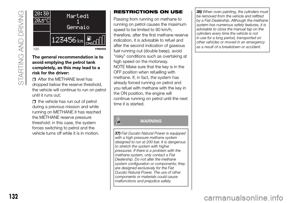
flashing and then the
indicator near
the CNG icon fig. 120 turns on.
Having reached the reserve methane
pressure threshold, and completely
filled the methane tank, the system
forces the switch to petrol for 5
seconds, with the aim of keeping the
petrol fuel supply system fully efficient.
119F1A0436
131
Page 134 of 296
The general recommendation is to
avoid emptying the petrol tank
completely, as this may lead to a
risk for the driver:
After the METHANE level has
dropped below the reserve threshold,
the vehicle will continue to run on petrol
until it runs out;
the vehicle has run out of petrol
during a previous mission and while
running on METHANE it has reached
the METHANE reserve pressure
threshold: in this case, the system
forces switching to petrol and the
vehicle turns off while it is in motion.RESTRICTIONS ON USE
Passing from running on methane to
running on petrol causes the maximum
speed to be limited to 90 km/h;
therefore, after the first methane reserve
indication, it is advisable to refuel and
after the second indication of gaseous
fuel running out (double beep), avoid
"risky" conditions such as overtaking at
high speed on the motorway.
NOTE Make sure that the key is in the
OFF position when refuelling with
methane. If, in fact, the system has
already forced running on petrol and
you refuel with methane with the key in
the ON position, the engine will
continue running on petrol until the next
time it is started.
WARNING
37)Fiat Ducato Natural Power is equipped
with a high pressure methane system
designed to run at 200 bar. It is dangerous
to stretch the system with higher
pressures. If there is a problem with the
methane system, only contact a Fiat
Dealership. Do not alter the methane
system configuration or components; they
are designed exclusively for the Fiat
Ducato Natural Power. The use of other
components or materials could cause
malfunctions and prejudice safety.38)When oven painting, the cylinders must
be removed from the vehicle and refitted
by a Fiat Dealership. Although the methane
system has numerous safety features, it is
advisable to close the manual tap on the
cylinders every time the vehicle is not
in use for a long period, transported on
other vehicles or moved in an emergency
as a result of a breakdown or accident.
120F0N0403I
132
STARTING AND DRIVING
Page 142 of 296
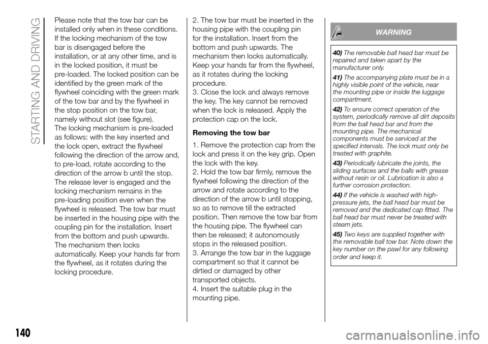
Please note that the tow bar can be
installed only when in these conditions.
If the locking mechanism of the tow
bar is disengaged before the
installation, or at any other time, and is
in the locked position, it must be
pre-loaded. The locked position can be
identified by the green mark of the
flywheel coinciding with the green mark
of the tow bar and by the flywheel in
the stop position on the tow bar,
namely without slot (see figure).
The locking mechanism is pre-loaded
as follows: with the key inserted and
the lock open, extract the flywheel
following the direction of the arrow and,
to pre-load, rotate according to the
direction of the arrow b until the stop.
The release lever is engaged and the
locking mechanism remains in the
pre-loading position even when the
flywheel is released. The tow bar must
be inserted in the housing pipe with the
coupling pin for the installation. Insert
from the bottom and push upwards.
The mechanism then locks
automatically. Keep your hands far from
the flywheel, as it rotates during the
locking procedure.2. The tow bar must be inserted in the
housing pipe with the coupling pin
for the installation. Insert from the
bottom and push upwards. The
mechanism then locks automatically.
Keep your hands far from the flywheel,
as it rotates during the locking
procedure.
3. Close the lock and always remove
the key. The key cannot be removed
when the lock is released. Apply the
protection cap on the lock.
Removing the tow bar
1. Remove the protection cap from the
lock and press it on the key grip. Open
the lock with the key.
2. Hold the tow bar firmly, remove the
flywheel following the direction of the
arrow and rotate according to the
direction of the arrow b until stopping,
so as to remove till the extracted
position. Then remove the tow bar from
the housing pipe. The flywheel can
then be released; it autonomously
stops in the released position.
3. Arrange the tow bar in the luggage
compartment so that it cannot be
dirtied or damaged by other
transported objects.
4. Insert the suitable plug in the
mounting pipe.
WARNING
40)The removable ball head bar must be
repaired and taken apart by the
manufacturer only.
41)The accompanying plate must be in a
highly visible point of the vehicle, near
the mounting pipe or inside the luggage
compartment.
42)To ensure correct operation of the
system, periodically remove all dirt deposits
from the ball head bar and from the
mounting pipe. The mechanical
components must be serviced at the
specified intervals. The lock must only be
treated with graphite.
43)Periodically lubricate the joints, the
sliding surfaces and the balls with grease
without resin or oil. Lubrication is also a
further corrosion protection.
44)If the vehicle is washed with high-
pressure jets, the ball head bar must be
removed and the dedicated cap fitted. The
ball head bar must never be treated with
steam jets.
45)Two keys are supplied together with
the removable ball tow bar. Note down the
key number on the pawl for any following
order and keep it.
140
STARTING AND DRIVING
Page 170 of 296

Message Signal Description
FMS1(2)
High beam, main beam Indicates active main beam headlight status
Low beam Indicates active dipped headlight status
Turn signals Indicates active direction indicator status
Hazard warning Indicates active hazard warning light status
Parking Brake Indicates parking brake engaged
Brake failure / brake system malfunction Indicates braking system fault
Hatch open Indicates rear door not shut
Fuel level Indicates fuel reserve warning light on
Engine coolant temperature Indicates engine coolant overheating warning light on
Battery charging condition Indicates insufficient battery charge warning light on
Engine oilIndicates insufficient engine oil pressure warning light
on
Position lights, side lights Indicates active side light status
Front fog lights Indicates active fog light status
Rear fog light Indicates active rear fog light status
Engine / Mil indicatorIndicates EOBD/injection system failure warning light
on
Service, call for maintenance Indicates scheduled service indicator displayed
Transmission failure / malfunction Indicates transmission system fault
Anti-lock brake system failure Indicates ABS failure warning light on
(2) The signal values are derived from information shown on the instrument panel
168
IN AN EMERGENCY
Page 176 of 296

146)The spare wheel supplied (for
versions/markets, where provided) is
specific for your vehicle. Therefore, it must
not be used on other models. Do not
use spare wheels of other models on your
vehicle. The wheel bolts are specific for
your vehicle: do not use them on different
models and do not use bolts from other
models on your car.
147)Repair and refit the standard wheel as
soon as possible. Do not apply grease to
the bolt threads before fitting: they could
come unscrewed.
148)Use the jack only to replace wheels
on the vehicle with which it is supplied
or on other vehicles of the same model.
Never use the jack for other purposes,
such as lifting other vehicle models. Never
use the jack to carry out repairs under
the vehicle. Incorrect positioning of the jack
may cause the lifted vehicle to fall. Do not
use the jack for loads higher than the
one shown on its label.
149)Never tamper with the inflation valve.
Never introduce tools of any kind between
rim and tyre. Check tyre and spare wheel
pressure regularly, referring to the values
shown in the "Technical specifications"
section.
150)No tools other than the crank
provided should be used with the spare
wheel lifting device; it should be operated
by hand only.
151)On versions equipped with self-
levelling air suspension, never introduce the
head or hands in the wheel arch: the
vehicle could raise or lower automatically
depending on possible load or temperature
changes.152)The device should only be operated
by hand, without using any type of tool
other than the crank provided like
pneumatic or electrical screwers.
153)The moving components of the jack
(screws and joints) can also cause injuries:
avoid touching them. If you come into
contact with lubricating grease, clean
yourself thoroughly.
154)At the end of the operation of
raising/locking the spare wheel, after
checking that the wheel is positioned
correctly under the platform (yellow notch
inside the window on the device), extract
the operating wrench. Take care not to turn
the wrench in the wrong direction (as in
fig. 166) to facilitate extracting it, to prevent
the attachment device from being
released and to ensure that the wheel
assembly remains safely fastened.
155)Each time the spare wheel is moved,
check that it is correctly positioned in its
housing under the platform. If it is not
correctly positioned, this could adversely
affect safety.
156)The spare wheel lifting device is
equipped with a clutch safety system for its
own protection; this could activated if an
excessive load is applied on the
maneuvering screw.FIX & GO
AUTOMATIC QUICK
TYRE REPAIR KIT
(for versions/markets, where provided)
The Fix & Go automatic quick tyre
repair kit is located at the front of the
vehicle passenger compartment and
includes fig. 171:
bottle A containing sealer and fitted
with:
– a transparent filler pipe B;
– a black pressure restoring pipe E;
– sticker C bearing the notice “max. 80
km/h”, to be placed in a position visible
to the driver (on the instrument panel)
after fixing the tyre;
171F1A0180
174
IN AN EMERGENCY
Page 205 of 296

WHEELS AND TYRES
Check the pressure of each tyre,
including the space-saver wheel,
approximately every two weeks and
before long journeys: the pressure
should be checked with the tyre rested
and cold.
It is normal for the pressure to increase
when the vehicle is used; for the correct
tyre inflation pressure, see “Wheels” in
the “Technical specifications” section.
Incorrect pressure causes abnormal
tyre wear fig. 194:
Anormal pressure: tread evenly worn;
Blow pressure: tread particularly worn
at the edges;
Chigh pressure: tread particularly worn
in the centre.
The tyres must be replaced when the
tread is less than 1.6 mm thick. In
any case, follow the laws in force in the
country you are in.
196) 197) 198) 199)
IMPORTANT
INFORMATION
As far as possible, avoid sharp
braking and screech starts. Be careful
not to hit the kerb, potholes or other
hard obstacles. Driving for long
stretches over uneven roads can
damage the tyres;
periodically check that the tyres
have no cuts in the side wall, abnormal
swelling or irregular tyre wear. Contact
a Fiat Dealership if required;
avoid overloading the car when
travelling: this may cause serious
damage to the wheels and tyres;
if a tyre is punctured, stop
immediately and change it to avoid
damage to the tyre, the rim,
suspensions and steering system;
tyres age even if they are not used a
great deal. Cracks in the tread and on
the side walls are a sign of ageing.
In any event, have the tyres checked by
specialised personnel if they have
been fitted for longer than 6 years.
Remember to check the spare wheel
very carefully;
in the case of replacement, always
fit new tyres, avoiding those of
unknown origin;
if a tyre is changed, also change the
inflation valve;
to allow even wear between the
front and rear tyres, it is advisable to
change them over every 10–15
thousand kilometres, keeping them on
the same side of the vehicle so as
not to reverse the direction of rotation.
IMPORTANT Replacing a tyre, check
that the tyre pressure monitoring
(TPMS) sensor is also taken from the
previous rim, together with the valve.
WARNING
196)Remember that the road holding
qualities of your vehicle also depend on the
correct inflation pressure of the tyres.
197)If the pressure is too low, the tyre will
overheat and could be seriously damaged.
198)Avoid switching the tyres from the
right side of the vehicle to the left side and
vice versa.
199)Never submit alloy rims to repainting
treatments requiring the use of
temperatures exceeding 150°C. The
mechanical properties of the wheels could
be impaired.
194F1A0240
203