Page 25 of 240
8)Do not activate the rain sensor while
washing the vehicle in an automatic
washing system.
9)If ice is found on the windscreen, make
sure that the device was disconnected
properly.
10)Do not use the rear window wiper to
remove layers of snow or ice. In such
conditions, the wiper may be subjected to
excessive stress and the motor cut-out
switch, which prevents operation for a few
seconds, may intervene. If operation is
not subsequently restored, contact a Fiat
Dealership.ROOF LIGHTS
FRONT ROOF LIGHT
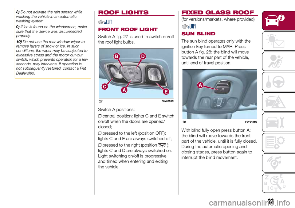
Switch A fig. 27 is used to switch on/off
the roof light bulbs.
Switch A positions:
❒central position: lights C and E switch
on/off when the doors are opened/
closed;
❒pressed to the left (position OFF):
lights C and E are always switched off;
❒pressed to the right (position
):
lights C and D are always switched on.
Light switching on/off is progressive
and timed when entering and exiting
the vehicle.
FIXED GLASS ROOF
(for versions/markets, where provided)
SUN BLIND
The sun blind operates only with the
ignition key turned to MAR. Press
button A fig. 28: the blind will move
towards the rear part of the vehicle,
until end of travel position.
With blind fully open press button A:
the blind will move towards the front
part of the vehicle, until it is fully closed.
During the automatic opening and
closing stages, press button again to
interrupt the blind movement.
27F0Y0098C
28F0Y0121C
23
Page 59 of 240
Warning light What it means
GENERIC FAILURE INDICATION
The warning light switches on in the following circumstances. In these cases contact a Fiat Dealership to
have the fault fixed as soon as possible:
❒Limit speed exceeded: on some versions, when the limit speed is exceeded, a message and a symbol
are displayed, along with a buzzer;
❒Fuel cut-off system intervention/failure
❒External light failure: the warning light switches on when a failure is detected in one of the following lights:
daytime running lights (DRL) (where provided)/side lights/direction indicator/rear fog light/reversing light/
number plate light/brake lights (for versions with multifunction display only). The fault relating to these lights
could be: one or more blown bulbs, a blown protection fuse or a break in the electrical connection;
❒DST (Dynamic Steering Torque or steering corrector) system failure
❒Water in diesel fuel filter
❒Stop/Start system failure
❒Methane level sensor failure (or LPG level)
❒Temporary or permanent City Brake Control - "Collision Mitigation" system failure
❒Rain sensor failure
❒Assisted parking failure
❒Dusk sensor failure
❒Engine oil pressure sensor failure(on versions with reconfigurable multifunction display the failure is
indicated by the switching on of the icon in the display)
❒Warning light failure
On some versions, the warning light switches on along with the display of a message and a symbol.
57
Page 110 of 240
IN AN EMERGENCY
A punctured tyre or a burnt-out bulb?
At times, a problem may interfere
with our journey.
The pages on emergencies can help
you to deal with critical situations
independently and with calm.
In an emergency we recommend that
you call the freephone number found in
the Warranty Booklet.
It is also possible to call the national or
international universal freephone
number to search for the nearest
Dealership.HAZARD WARNING LIGHTS...........109
CHANGING A WHEEL ....................109
"FIX&GO AUTOMATIC" KIT .............113
REPLACING A BULB ......................115
REPLACING FUSES........................122
JUMP STARTING ............................128
FUEL CUT-OFF SYSTEM ................129
TOWING THE VEHICLE ..................130
108
IN AN EMERGENCY
Page 117 of 240
127)If the pressure has fallen below 1.8
bar, do not drive any further: the Fix&Go
Automatic kit cannot guarantee proper
hold because the tyre is too damaged.
Contact a Fiat Dealership.
128)You must always indicate that the tyre
was repaired using the Fix&Go Automatic
kit. Give the booklet to the technicians who
will be handling the tyre that was treated
using the Fix&Go Automatic kit.
129)Repairs are not possible in the case of
damage to the wheel rim (bad groove
distortion causing air loss). Do not remove
foreign bodies (screws or nails) from the
tyre.
130)Never operate the compressor for
longer than 20 consecutive minutes. Risk
of overheating. The Fix&Go Automatic kit is
not suitable for definitive repairs, so the
repaired tyres may only be used
temporarily.
131)The information required by current
regulations, regarding the chemical
substances for the protection of human
health and the environment and on the safe
use of the sealing fluid, are on the
packaging label. Compliance with the
indications on the label is an essential
condition to ensure the safety and
the effectiveness of the product.
Remember to carefully read the label
before use; the user of the product
is responsible for any damages caused by
improper use. The sealing fluid has an
expiry date. Replace the bottle if the
sealant has expired.
WARNING
64)In the event of a puncture caused by
foreign bodies, the kit may be used to
repair tyres showing damage on the tread
or shoulder up to max. 4 mm diameter.
WARNING
3)Dispose of the bottle and the sealant
properly. Dispose of the components
in compliance with national and local
regulations.
REPLACING A BULB
132) 133)65) 66)
GENERAL
INSTRUCTIONS
❒Before changing a bulb check the
contacts for oxidation;
❒burnt bulbs must be replaced by
others of the same type and power;
❒after replacing a headlight bulb,
always check the correct alignment of
the light beam;
❒when a light is not working, check
that the corresponding fuse is intact
before changing a bulb. For the location
of fuses, refer to the paragraph “If a
fuse blows” in this section;
115
Page 119 of 240
TYPES OF BULBS
UseType Power
Dipped/main beam headlights H7 55 W
Front side lights/Day lights (DRL) W21/5W 21W/5W
Rear side lights/Brake lights P21/5W 21W/5W
Front direction indicators WY21W 21 W
Side direction indicators WY5W 5 W
Rear direction indicators P21W 21 W
3
rdBrake LED –
Fog lights H11 55 W
Reverse W16W 16 W
Rear fog light W16W 16 W
Number plate C5W 5 W
Front roof light C5W 5 W
Front roof lights (sun visors) C5W 5 W
Luggage compartment light W5W 5 W
Glove compartment light C5W 5 W
Rear roof lights C5W 5 W
117
Page 120 of 240

FRONT UPPER LIGHT
CLUSTER
This contains the bulbs for direction
indicators and dipped beam headlights.
The bulbs are arranged as follows
117:
ADirection indicators
BDipped beam headlights
DIRECTION INDICATORS
To replace the bulb, proceed as follows:
❒remove cover A fig. 117;
❒turn bulb holder B fig. 118
anticlockwise, extract bulb C and
replace it;
❒refit the new bulb on the bulb holder,
making sure it is correctly locked;
❒refit the bulb holder in its housing and
turn it clockwise, until the locking click
is heard;
❒then refit the cover A fig. 117.
DIPPED BEAM
HEADLIGHTS
To replace the bulb, proceed as follows:
❒remove cover B fig. 117;
❒remove the connector and bulb
holder C fig. 119 unit, releasing it
outwards;
❒remove bulb D from connector E and
replace it;
❒refit the new bulb on the connector,
making sure it is correctly locked;❒refit the connector and bulb holder C
unit in its housing;
❒then refit the cover B fig. 117.
FRONT LOWER LIGHT
CLUSTER
This contains the bulbs for the main
beams and side lights/daytime running
lights (DRL).
The bulbs are arranged as follows fig.
120:
CMain beam headlights
DSide lights/daytime running lights
(DRL)
MAIN BEAM HEADLIGHTS
To replace the bulb, proceed as
follows:
❒steer the wheel completely inwards;
❒undo the screws A fig. 121 and
remove the flap B;
❒remove cover C fig. 122;
117F0Y0021C
118F0Y0022C
119F0Y0023C
120F0Y0024C
118
IN AN EMERGENCY
fig.
Page 121 of 240
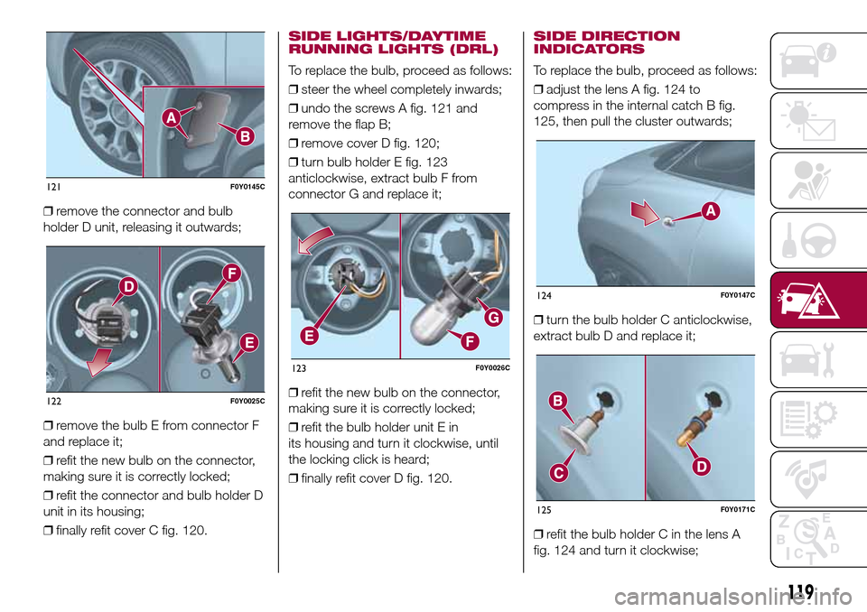
❒remove the connector and bulb
holder D unit, releasing it outwards;
❒remove the bulb E from connector F
and replace it;
❒refit the new bulb on the connector,
making sure it is correctly locked;
❒refit the connector and bulb holder D
unit in its housing;
❒finally refit cover C fig. 120.
SIDE LIGHTS/DAYTIME
RUNNING LIGHTS (DRL)
To replace the bulb, proceed as follows:
❒steer the wheel completely inwards;
❒undo the screws A fig. 121 and
remove the flap B;
❒remove cover D fig. 120;
❒turn bulb holder E fig. 123
anticlockwise, extract bulb F from
connector G and replace it;
❒refit the new bulb on the connector,
making sure it is correctly locked;
❒refit the bulb holder unit E in
its housing and turn it clockwise, until
the locking click is heard;
❒finally refit cover D fig. 120.
SIDE DIRECTION
INDICATORS
To replace the bulb, proceed as follows:
❒adjust the lens A fig. 124 to
compress in the internal catch B fig.
125, then pull the cluster outwards;
❒turn the bulb holder C anticlockwise,
extract bulb D and replace it;
❒refit the bulb holder C in the lens A
fig. 124 and turn it clockwise;
121F0Y0145C
122F0Y0025C
123F0Y0026C
124F0Y0147C
125F0Y0171C
119
Page 122 of 240
❒refit the cluster making sure that the
internal catch B fig. 125 clips into
position.
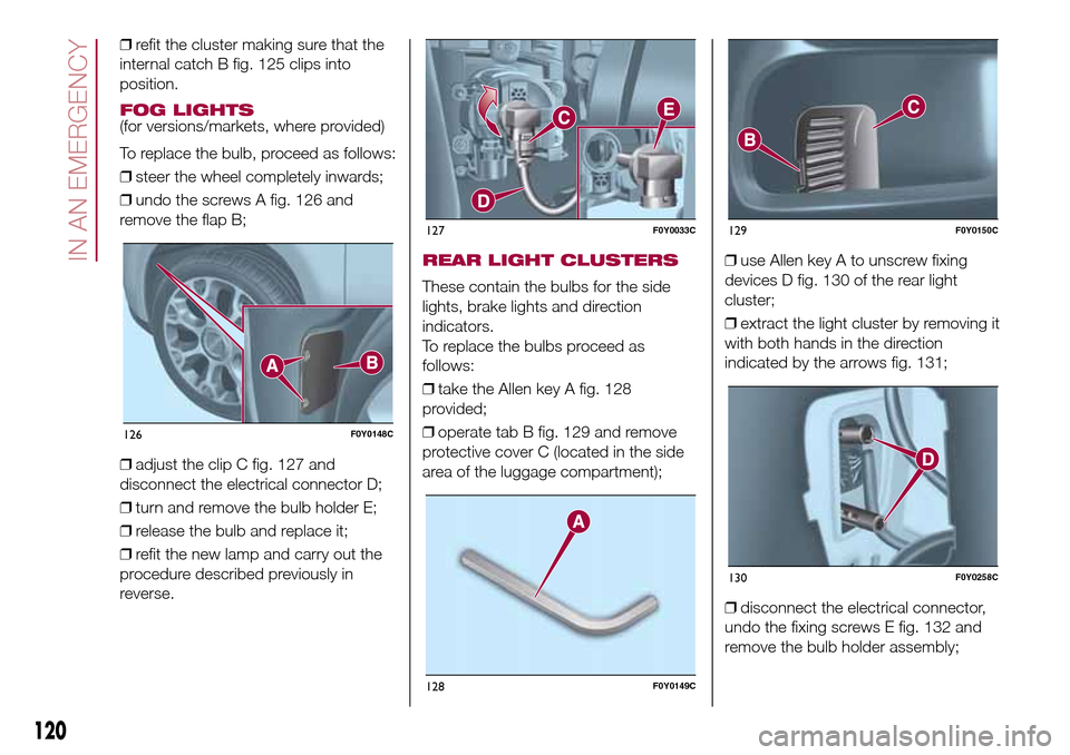
FOG LIGHTS(for versions/markets, where provided)
To replace the bulb, proceed as follows:
❒steer the wheel completely inwards;
❒undo the screws A fig. 126 and
remove the flap B;
❒adjust the clip C fig. 127 and
disconnect the electrical connector D;
❒turn and remove the bulb holder E;
❒release the bulb and replace it;
❒refit the new lamp and carry out the
procedure described previously in
reverse.
REAR LIGHT CLUSTERS
These contain the bulbs for the side
lights, brake lights and direction
indicators.
To replace the bulbs proceed as
follows:
❒take the Allen key A fig. 128
provided;
❒operate tab B fig. 129 and remove
protective cover C (located in the side
area of the luggage compartment);❒use Allen key A to unscrew fixing
devices D fig. 130 of the rear light
cluster;
❒extract the light cluster by removing it
with both hands in the direction
indicated by the arrows fig. 131;
❒disconnect the electrical connector,
undo the fixing screws E fig. 132 and
remove the bulb holder assembly;
126F0Y0148C
127F0Y0033C
128F0Y0149C
129F0Y0150C
130F0Y0258C
120
IN AN EMERGENCY