Page 457 of 707
Bi-Level ModeAir comes from both the headliner outlets and the
floor outlets.
NOTE: In many temperature positions, the Bi-Level
mode is designed to provide cooler air out of the head-
liner outlets and warmer air from the floor outlets.
Floor Mode
Air comes from the floor outlets.Rear Automatic Temperature Control (ATC) — If
Equipped
The rear ATC system has floor air outlets at the rear of the
right side sliding door, and overhead outlets at each
outboard rear seating position. The system provides
heated air through the floor outlets or cool, dehumidified
air through the headliner outlets.
The rear system temperature control is on the front ATC
panel located on the instrument panel.
Pushing the Rear Temperature Lock button on the front
ATC panel, illuminates a lock symbol in the rear display.
The rear temperature and air source are controlled from
the front ATC panel.
Rear second row occupants can only adjust the rear ATC
control when the Rear Temperature Lock button is turned
off.
4
UNDERSTANDING YOUR INSTRUMENT PANEL 455
Page 458 of 707
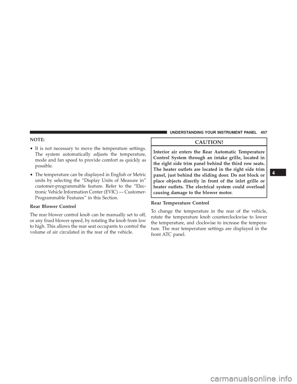
The rear ATC system is located in the headliner, near the
center of the vehicle.1. Push the Rear Temperature Lock button on the front
ATC panel. This turns off the Rear Temperature Lock
icon in the rear temperature knob.
2. Rotate the Rear Blower, Rear Temperature and the Rear Mode Control knobs to suit your comfort needs.
3. ATC is selected by adjusting the rear blower knob counterclockwise to AUTO.
Once the desired temperature is displayed, the ATC
System will automatically achieve and maintain that
comfort level. When the system is set up for your comfort
level, it is not necessary to change the settings. You will
experience the greatest efficiency by simply allowing the
system to function automatically.
Rear ATC Control Features
1 — Blower Speed 3 — Rear Mode
2 — Rear Temperature 4 — Rear Temperature Lock
456 UNDERSTANDING YOUR INSTRUMENT PANEL
Page 459 of 707
NOTE:
•It is not necessary to move the temperature settings.
The system automatically adjusts the temperature,
mode and fan speed to provide comfort as quickly as
possible.
• The temperature can be displayed in English or Metric
units by selecting the “Display Units of Measure in”
customer-programmable feature. Refer to the “Elec-
tronic Vehicle Information Center (EVIC) — Customer-
Programmable Features” in this Section.
Rear Blower Control
The rear blower control knob can be manually set to off,
or any fixed blower speed, by rotating the knob from low
to high. This allows the rear seat occupants to control the
volume of air circulated in the rear of the vehicle.
CAUTION!
Interior air enters the Rear Automatic Temperature
Control System through an intake grille, located in
the right side trim panel behind the third row seats.
The heater outlets are located in the right side trim
panel, just behind the sliding door. Do not block or
place objects directly in front of the inlet grille or
heater outlets. The electrical system could overload
causing damage to the blower motor.
Rear Temperature Control
To change the temperature in the rear of the vehicle,
rotate the temperature knob counterclockwise to lower
the temperature, and clockwise to increase the tempera-
ture. The rear temperature settings are displayed in the
front ATC panel.
4
UNDERSTANDING YOUR INSTRUMENT PANEL 457
Page 460 of 707
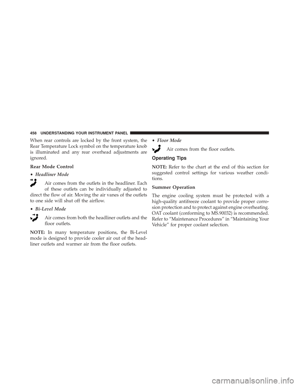
When rear controls are locked by the front system, the
Rear Temperature Lock symbol on the temperature knob
is illuminated and any rear overhead adjustments are
ignored.
Rear Mode Control
•Headliner Mode
Air comes from the outlets in the headliner. Each
of these outlets can be individually adjusted to
direct the flow of air. Moving the air vanes of the outlets
to one side will shut off the airflow.
• Bi-Level Mode
Air comes from both the headliner outlets and the
floor outlets.
NOTE: In many temperature positions, the Bi-Level
mode is designed to provide cooler air out of the head-
liner outlets and warmer air from the floor outlets. •
Floor Mode
Air comes from the floor outlets.
Operating Tips
NOTE: Refer to the chart at the end of this section for
suggested control settings for various weather condi-
tions.
Summer Operation
The engine cooling system must be protected with a
high-quality antifreeze coolant to provide proper corro-
sion protection and to protect against engine overheating.
OAT coolant (conforming to MS.90032) is recommended.
Refer to “Maintenance Procedures” in “Maintaining Your
Vehicle” for proper coolant selection.
458 UNDERSTANDING YOUR INSTRUMENT PANEL
Page 463 of 707
STARTING AND OPERATING
CONTENTS
�STARTING PROCEDURES ................465
▫ Automatic Transmission ................465
▫ Normal Starting ...................... .465
▫ Extreme Cold Weather
(Below –20°F Or �29°C) ................466
▫ If The Engine Fails To Start ..............466
▫ After Starting ....................... .467
� ENGINE BLOCK HEATER — IF EQUIPPED . . .468
� AUTOMATIC TRANSMISSION ............468
▫ Key Ignition Park Interlock ...............470 ▫
Brake/Transmission Shift Interlock System . . .470
▫ Fuel Economy (ECON) Mode .............471
▫ Six-Speed Automatic Transmission .........472
▫ Gear Ranges ........................ .473
� DRIVING ON SLIPPERY SURFACES .........481
▫ Acceleration ........................ .481
▫ Traction ........................... .481
� DRIVING THROUGH WATER .............482
▫ Flowing/Rising Water ..................482
▫ Shallow Standing Water .................482
5
Page 464 of 707

�POWER STEERING .....................483
▫ Power Steering Fluid Check ..............484
� PARKING BRAKE ..................... .485
� BRAKE SYSTEM ...................... .488
� ELECTRONIC BRAKE CONTROL SYSTEM . . . .488
▫ Electronic Brake Force Distribution (EBD) . . . .488
▫ Brake System Warning Light ..............489
▫ Anti-Lock Brake System (ABS) ............489
▫ Anti-Lock Brake Warning Light ............491
▫ Brake Assist System (BAS) ...............491
▫ Hill Start Assist (HSA) .................492
▫ Traction Control System (TCS) ............495
▫ Electronic Stability Control (ESC) ..........495▫
Electronic Roll Mitigation (ERM) ...........499
▫ Trailer Sway Control (TSC) ..............500
� TIRE SAFETY INFORMATION .............501
▫ Tire Markings ....................... .501
▫ Tire Identification Number (TIN) ...........504
▫ Tire Terminology And Definitions ..........506
▫ Tire Loading And Tire Pressure ...........507
� TIRES — GENERAL INFORMATION ........512
▫ Tire Pressure ....................... .512
▫ Tire Inflation Pressures .................513
▫ Tire Pressures For High Speed Operation . . . .515
▫ Radial Ply Tires ..................... .515
▫ Tire Types .......................... .516
462 STARTING AND OPERATING
Page 467 of 707
STARTING PROCEDURES
Before starting your vehicle, adjust your seat, adjust the
inside and outside mirrors, fasten your seat belt, and if
present, instruct all other occupants to buckle their seat
belts.
WARNING!
•When leaving the vehicle, always remove the Key
Fob from the ignition and lock your vehicle.
• Never leave children alone in a vehicle, or with
access to an unlocked vehicle.
• Allowing children to be in a vehicle unattended is
dangerous for a number of reasons. A child or
others could be seriously or fatally injured. Chil-
dren should be warned not to touch the parking
brake, brake pedal or the shift lever.
(Continued)
WARNING! (Continued)
•Do not leave the Key Fob in or near the vehicle, or
in a location accessible to children and do not leave
the ignition of a vehicle equipped with Keyless
Enter-N-Go in the ACC or ON/RUN Mode. A child
could operate power windows, other controls, or
move the vehicle.
Automatic Transmission
The shift lever must be in the NEUTRAL or PARK
position before you can start the engine. Press the brake
pedal before shifting into any driving gear.
Normal Starting
1. Do not press the accelerator.
5
STARTING AND OPERATING 465
Page 468 of 707
2. Use the Fob with Integrated Key to briefly turn theignition switch to the START position and release it as
soon as the starter engages. The starter motor will
continue to run, and it will disengage automatically
when the engine is running.
3. If the engine fails to start, the starter will disengage automatically in 10 seconds. If this occurs, turn the
ignition switch to the OFF position, wait 10 to 15
seconds, then repeat the “Normal Starting” procedure
(Steps 1–3 above).
NOTE: This vehicle is equipped with a transmission
shift interlocking system. The brake pedal must be
pressed to shift out of PARK.
Extreme Cold Weather (Below –20°F Or �29°C)
To ensure reliable starting at these temperatures, use of
an externally powered electric engine block heater (avail-
able from your authorized dealer) is recommended.
If The Engine Fails To Start
WARNING!
• Never pour fuel or other flammable liquids into
the throttle body air inlet opening in an attempt to
start the vehicle. This could result in a flash fire
causing serious personal injury.
• Do not attempt to push or tow your vehicle to get it
started. Vehicles equipped with an automatic trans-
mission cannot be started this way. Unburned fuel
could enter the catalytic converter and once the
engine has started, ignite and damage the converter
and vehicle.
(Continued)
466 STARTING AND OPERATING