Page 489 of 661

Fuel System Cautions
CAUTION!
Follow these guidelines to maintain your vehicle’s
performance:
•The use of leaded gasoline is prohibited by Federal
law. Using leaded gasoline can impair engine per-
formance and damage the emissions control sys-
tem.
• An out-of-tune engine or certain fuel or ignition
malfunctions can cause the catalytic converter to
overheat. If you notice a pungent burning odor or
some light smoke, your engine may be out of tune
or malfunctioning and may require immediate ser-
vice. Contact your authorized dealer for service
assistance.
(Continued)
CAUTION! (Continued)
•The use of fuel additives, which are now being
sold as octane enhancers, is not recommended.
Most of these products contain high concentrations
of methanol. Fuel system damage or vehicle perfor-
mance problems resulting from the use of such
fuels or additives is not the responsibility of the
manufacturer and may void or not be covered
under the New Vehicle Limited Warranty.
NOTE: Intentional tampering with the emissions control
system can result in civil penalties being assessed against
you.
5
STARTING AND OPERATING 487
Page 494 of 661
ADDING FUEL
1. Push the fuel filler door release switch (located in thedriver’s door map pocket).
2. Open the fuel filler door. NOTE:
In certain cold conditions, ice may prevent the
fuel door from opening. If this occurs, lightly push on the
fuel door to break the ice buildup and re-release the fuel
door using the inside release button. Do not pry on the
door.
Fuel Filler Door Release Switch
Fuel Filler Door
492 STARTING AND OPERATING
Page 496 of 661
WARNING!
•Never have any smoking materials lit in or near the
vehicle when the fuel door is open or the tank is
being filled.
• Never add fuel when the engine is running. This is
in violation of most state and federal fire regula-
tions and may cause the “Malfunction Indicator
Light” to turn on.
• A fire may result if fuel is pumped into a portable
container that is inside of a vehicle. You could be
burned. Always place fuel containers on the
ground while filling.
Emergency Fuel Filler Door Release
If you are unable to open the fuel filler door, use the fuel
filler door emergency release located in the trunk. Follow the steps below to open the fuel door in case of an
emergency:
1. Open the trunk.
2. Remove the access cover (located on the left side inner
trim panel).
Access Cover
494 STARTING AND OPERATING
Page 502 of 661

WARNING!
•An improperly adjusted Weight Distributing Hitch
system may reduce handling, stability, braking
performance, and could result in a collision.
• Weight Distributing Systems may not be compat-
ible with Surge Brake Couplers. Consult with your
hitch and trailer manufacturer or a reputable Rec-
reational Vehicle dealer for additional information.
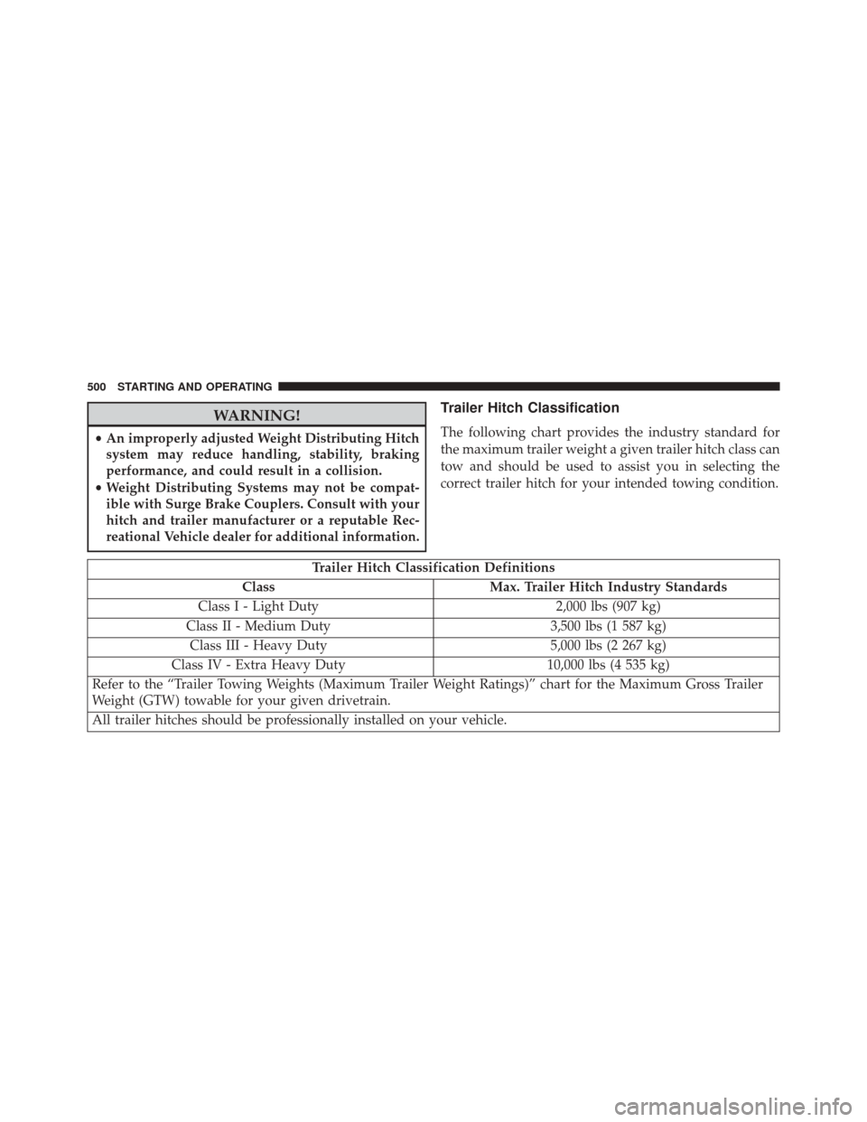
Trailer Hitch Classification
The following chart provides the industry standard for
the maximum trailer weight a given trailer hitch class can
tow and should be used to assist you in selecting the
correct trailer hitch for your intended towing condition.
Trailer Hitch Classification Definitions
Class Max. Trailer Hitch Industry Standards
Class I - Light Duty 2,000 lbs (907 kg)
Class II - Medium Duty 3,500 lbs (1 587 kg)
Class III - Heavy Duty 5,000 lbs (2 267 kg)
Class IV - Extra Heavy Duty 10,000 lbs (4 535 kg)
Refer to the “Trailer Towing Weights (Maximum Trailer Weight Ratings)” chart for the Maximum Gross Trailer
Weight (GTW) towable for your given drivetrain.
All trailer hitches should be professionally installed on your vehicle.
500 STARTING AND OPERATING
Page 508 of 661
CAUTION!
If the trailer weighs more than 1,000 lbs (453 kg)
loaded, it should have its own brakes and they
should be of adequate capacity. Failure to do this
could lead to accelerated brake lining wear, higher
brake pedal effort, and longer stopping distances.
Towing Requirements — Trailer Lights And Wiring
Whenever you pull a trailer, regardless of the trailer size,
stoplights and turn signals on the trailer are required for
motoring safety.
The Trailer Tow Package may include a four- and seven-
pin wiring harness. Use a factory approved trailer har-
ness and connector.
NOTE:Do not cut or splice wiring into the vehicles
wiring harness. The electrical connections are all complete to the vehicle
but you must mate the harness to a trailer connector.
Refer to the following illustrations.
Four-Pin Connector
1 — Female Pins
2 — Male Pin
3 — Ground4 — Park
5 — Left Stop/Turn
6 — Right Stop/Turn
506 STARTING AND OPERATING
Page 510 of 661

Electronic Speed Control — If Equipped
•Do not use in hilly terrain or with heavy loads.
• When using the speed control, if you experience speed
drops greater than 10 mph (16 km/h), disengage until
you can get back to cruising speed.
• Use speed control in flat terrain and with light loads to
maximize fuel efficiency.
AutoStick
• When using the AutoStick shift control, select the
highest gear that allows for adequate performance and
avoids frequent downshifts. For example, choose “5” if
the desired speed can be maintained. Choose “4” or
“3” if needed to maintain the desired speed. •
To prevent excess heat generation, avoid continuous
driving at high RPM. Reduce vehicle speed as neces-
sary to avoid extended driving at high RPM. Return to
a higher gear or vehicle speed when grade and road
conditions allow.
Cooling System
To reduce potential for engine and transmission over-
heating, take the following actions:
City Driving
When stopped for short periods of time, shift the trans-
mission into NEUTRAL and increase engine idle speed.
Highway Driving
Reduce speed.
Air Conditioning
Turn off temporarily.
508 STARTING AND OPERATING
Page 525 of 661
NOTE:•For vehicles so equipped, do not attempt to install a
center cap or wheel cover on the compact spare.
• Refer to “Compact Spare Tire” and to “Limited-Use
Spare” under “Tires—General Information” in
“Starting and Operating” for additional warnings,
cautions, and information about the spare tire, its
use, and operation.
8. Install the lug nuts with the cone shaped end of the lug nut toward the wheel. Lightly tighten the lug nuts.
WARNING!
To avoid the risk of forcing the vehicle off the jack,
do not tighten the lug nuts fully until the vehicle has
been lowered. Failure to follow this warning may
result in personal injury.
Mounting Spare Tire
6
WHAT TO DO IN EMERGENCIES 523
Page 526 of 661

9. Lower the vehicle to the ground by turning the jackhandle counterclockwise.
10. Refer to Torque Specifications for proper lug nut torque.
11. Stow the jack, tools and flat tire. Make sure the base of the jack faces the front of the vehicle before
tightening down the fastener.
WARNING!
A loose tire or jack thrown forward in a collision or
hard stop could endanger the occupants of the ve-
hicle. Always stow the jack parts and the spare tire in
the places provided. Have the deflated (flat) tire
repaired or replaced immediately.
Road Tire Installation
1. Mount the road tire on the axle. 2. Install the remaining lug nuts with the cone shaped
end of the nut toward the wheel. Lightly tighten the
lug nuts.
WARNING!
To avoid the risk of forcing the vehicle off the jack,
do not tighten the lug nuts fully until the vehicle has
been lowered. Failure to follow this warning may
result in personal injury.
3. Lower the vehicle to the ground by turning the jack handle counterclockwise.
4. Refer to Torque Specifications for proper lug nut torque.
5. After 25 miles (40 km) check the lug nut torque with a torque wrench to ensure that all lug nuts are properly
seated against the wheel.
524 WHAT TO DO IN EMERGENCIES