Page 529 of 727
EXAMPLE:
H = Speed Symbol
– A symbol indicating the range of speeds at which a tire can carry a load corresponding to
its load index under certain operating conditions
– The maximum speed corresponding to the speed symbol should only be achieved under
specified operating conditions (i.e., tire pressure, vehicle loading, road conditions, and
posted speed limits)
Load Identification:
Absence of the following load identification symbols on the sidewall of the tire indicates a Standard Load (SL)
tire:
•XL = Extra load (or reinforced) tire, or
•LL= Light load tire or
•C, D, E, F, G = Load range associated with the maximum load a tire can carry at a specified pressure
Maximum Load – Maximum load indicates the maximum load this tire is designed to carry
Maximum Pressure – Maximum pressure indicates the maximum permissible cold tire inflation pressure for this
tire
5
STARTING AND OPERATING 527
Page 597 of 727

WARNING!(Continued)
•Keep Tire Service Kit away from open flames or
heat source.
• A loose Tire Service Kit thrown forward in a
collision or hard stop could endanger the occupants
of the vehicle. Always stow the Tire Service Kit in
the place provided. Failure to follow these warn-
ings can result in injuries that are serious or fatal to
you, your passengers, and others around you.
• Take care not to allow the contents of Tire Service
Kit to come in contact with hair, eyes, or clothing.
Tire Service Kit sealant is harmful if inhaled,
swallowed, or absorbed through the skin. It causes
skin, eye, and respiratory irritation. Flush immedi-
ately with plenty of water if there is any contact
with eyes or skin. Change clothing as soon as
possible, if there is any contact with clothing.
(Continued)
WARNING! (Continued)
•Tire Service Kit Sealant solution contains latex. In
case of an allergic reaction or rash, consult a phy-
sician immediately. Keep Tire Service Kit out of
reach of children. If swallowed, rinse mouth imme-
diately with plenty of water and drink plenty of
water. Do not induce vomiting! Consult a physician
immediately.
Sealing A Tire With Tire Service Kit
(A) Whenever You Stop To Use Tire Service Kit:
1. Pull over to a safe location and turn on the vehicle’s Hazard Warning flashers.
2. Verify that the valve stem (on the wheel with the deflated tire) is in a position that is near to the ground.
This will allow the Tire Service Kit Hoses (6) and (7) to
reach the valve stem and keep the Tire Service Kit flat
6
WHAT TO DO IN EMERGENCIES 595
Page 612 of 727
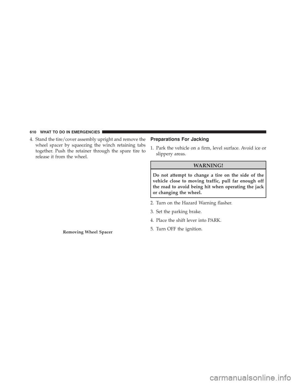
4. Stand the tire/cover assembly upright and remove thewheel spacer by squeezing the winch retaining tabs
together. Push the retainer through the spare tire to
release it from the wheel.Preparations For Jacking
1. Park the vehicle on a firm, level surface. Avoid ice orslippery areas.
WARNING!
Do not attempt to change a tire on the side of the
vehicle close to moving traffic, pull far enough off
the road to avoid being hit when operating the jack
or changing the wheel.
2. Turn on the Hazard Warning flasher.
3. Set the parking brake.
4. Place the shift lever into PARK.
5. Turn OFF the ignition.
Removing Wheel Spacer
610 WHAT TO DO IN EMERGENCIES
Page 615 of 727
2. There are two jack engagement locations on each sideof the vehicle body. These locations are on the sill
flange of the vehicle body.CAUTION!
Do not attempt to raise the vehicle by jacking on
locations other than those indicated.
Rear jack locations are between a pair of down-facing
tabs on the sill flange of the vehicle side body.
Jack Locations
Rear Jacking Locations
6
WHAT TO DO IN EMERGENCIES 613
Page 621 of 727
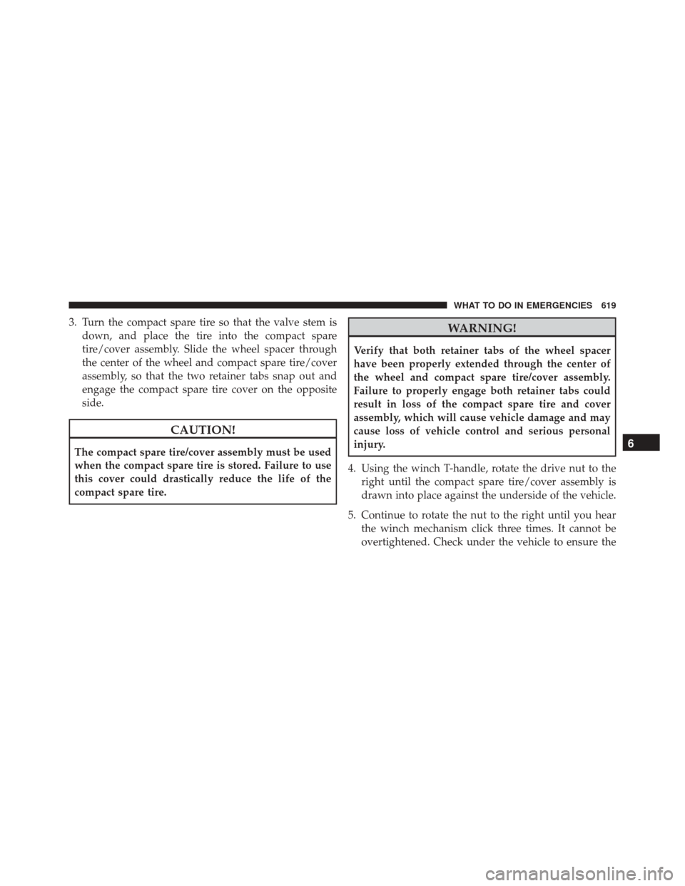
3. Turn the compact spare tire so that the valve stem isdown, and place the tire into the compact spare
tire/cover assembly. Slide the wheel spacer through
the center of the wheel and compact spare tire/cover
assembly, so that the two retainer tabs snap out and
engage the compact spare tire cover on the opposite
side.
CAUTION!
The compact spare tire/cover assembly must be used
when the compact spare tire is stored. Failure to use
this cover could drastically reduce the life of the
compact spare tire.
WARNING!
Verify that both retainer tabs of the wheel spacer
have been properly extended through the center of
the wheel and compact spare tire/cover assembly.
Failure to properly engage both retainer tabs could
result in loss of the compact spare tire and cover
assembly, which will cause vehicle damage and may
cause loss of vehicle control and serious personal
injury.
4. Using the winch T-handle, rotate the drive nut to the right until the compact spare tire/cover assembly is
drawn into place against the underside of the vehicle.
5. Continue to rotate the nut to the right until you hear the winch mechanism click three times. It cannot be
overtightened. Check under the vehicle to ensure the
6
WHAT TO DO IN EMERGENCIES 619
Page 649 of 727

4. Disengage the two retaining tabs that secure the filtercover to the HVAC housing, and remove the cover.
5. Remove the A/C air filter by pulling it straight out of the housing.
6. Install the A/C air filter with the arrow on the filter pointing toward the floor. When installing the filter cover, make sure the retaining tabs fully engage the
cover.
CAUTION!
The A/C air filter is identified with an arrow to
indicate airflow direction through the filter. Failure
to properly install the filter will result in the need to
replace it more often.
7. Rotate the glove compartment door back into position.
Body Lubrication
Locks and all body pivot points, including such items as
seat tracks, door hinge pivot points and rollers, liftgate,
tailgate, decklid, sliding doors and hood hinges, should
be lubricated periodically with a lithium based grease,
such as MOPAR Spray White Lube to assure quiet, easy
operation and to protect against rust and wear. Prior to
the application of any lubricant, the parts concerned
A/C Air Filter Replacement
7
MAINTAINING YOUR VEHICLE 647
Page 659 of 727

WARNING!(Continued)
•To avoid contamination from foreign matter or
moisture, use only new brake fluid or fluid that has
been in a tightly closed container. Keep the master
cylinder reservoir cap secured at all times. Brake
fluid in a open container absorbs moisture from the
air resulting in a lower boiling point. This may
cause it to boil unexpectedly during hard or pro-
longed braking, resulting in sudden brake failure.
This could result in a collision.
• Overfilling the brake fluid reservoir can result in
spilling brake fluid on hot engine parts, causing
the brake fluid to catch fire. Brake fluid can also
damage painted and vinyl surfaces, care should be
taken to avoid its contact with these surfaces.
WARNING! (Continued)
•Do not allow petroleum based fluid to contaminate
the brake fluid. Brake seal components could be
damaged, causing partial or complete brake failure.
This could result in a collision.
Automatic Transmission
Selection Of Lubricant
It is important to use the proper transmission fluid to
ensure optimum transmission performance and life. Use
only the manufacturer’s specified transmission fluid.
Refer to “Fluids, Lubricants, And Genuine Parts” in this
section for fluid specifications. It is important to maintain
the transmission fluid at the correct level using the
recommended fluid. No chemical flushes should be used
in any transmission; only the approved lubricant should
be used.
7
MAINTAINING YOUR VEHICLE 657
Page 668 of 727

the liner thoroughly under warm running water. Shake
the excess water from the liner and dry the outer surfaces
with a clean soft cloth.
Installation
Place the liner into the cupholder drawer and push the
liner into place so that the retention tabs seat into the
corresponding openings in the drawer.
FUSES
WARNING!
•When replacing a blown fuse, always use an ap-
propriate replacement fuse with the same amp
rating as the original fuse. Never replace a fuse
with another fuse of higher amp rating. Never
replace a blown fuse with metal wires or any other
(Continued)
WARNING! (Continued)
material. Failure to use proper fuses may result in
serious personal injury, fire and/or property dam-
age.
• Before replacing a fuse, make sure that the ignition
is off and that all the other services are switched off
and/or disengaged.
• If the replaced fuse blows again, contact an autho-
rized dealer.
• If a general protection fuse for safety systems (air
bag system, braking system), power unit systems
(engine system, gearbox system) or steering system
blows, contact an authorized dealer.
Totally Integrated Power Module (Fuses)
The Totally Integrated Power Module is located in the
engine compartment near the battery. Refer to the appli-
cable “Engine Compartment” illustration in this section.
666 MAINTAINING YOUR VEHICLE