2016 BMW X6M Page 76
[x] Cancel search: Page 76Page 112 of 255

front passenger side are not
activated.▷The indicator lamp does not light up when,
e.g., a correctly seated person of sufficient
size is detected on the seat. The airbags
on the front passenger side are activated.
Detected child seats
The system generally detects children seated
in a child seat, particularly in child seats re‐
quired by NHTSA when the vehicle was manu‐ factured. After installing a child seat, make
sure that the indicator lamp for the front-seat
passenger airbags lights up. This indicates
that the child seat has been detected and the
front-seat passenger airbags are not activated.
Strength of the driver's and front-seat
passenger airbag
The explosive power that activates driver's/
front passenger's airbags very much depends
on the positions of the driver's/front passeng‐ er's seat.
With a respective message appearing on Con‐
trol Display calibrate the front seats to keep the accuracy of this function over the long-
term.
Calibrating the front seats WARNING
There is risk of jamming when moving
the seats. There is risk of injuries or risk of
property damage. Make sure that the area of
movement of the seat is clear prior to any ad‐
justment.◀
A corresponding message appears on the
Control Display.
1.Press the switch and move the respective
seat all the way forward.2.Press the switch forward again. The seat
still moves forward slightly.3.Readjust the seat to the desired position.The calibration procedure is completed when
the message on the Control Display disap‐
pears.
If the message continues to be displayed, re‐
peat the calibration.
If the message does not disappear after a re‐
peat calibration, have the system checked as
soon as possible.
Tire Pressure Monitor TPM
The concept The system monitors tire inflation pressure in
the four mounted tires. The system warns you
if there is a significant loss of pressure in one
or more tires. For this purpose, sensors in the
tire valves measure the tire inflation pressure
and tire temperature.
Information With use of the system observe further infor‐
mation found under Tire inflation pressure, re‐
fer to page 200.
Functional requirements
The system must have been reset with the
correct tire inflation pressure; otherwise, relia‐
ble signaling of tire inflation pressure loss is
not assured.
Reset the system after each adjustment of the
tire inflation pressure and after every tire or
wheel change.
Always use wheels with TPM electronics to
ensure that the system will operate properly.
Status display The current status of the Tire Pressure Moni‐
tor TPM can be displayed on the Control Dis‐
play, e.g., whether or not the TPM is active.
On the Control Display:1."Vehicle info"2."Vehicle status"Seite 112ControlsSafety112
Online Edition for Part no. 01 40 2 964 090 - VI/15
Page 116 of 255

the Mobility System. If the tire inflation
pressure in all tires is correct, the Flat Tire
Monitor may not have been initialized. In
this case, initialize the system.3.Repair flat tire with the Mobility System or
replace the damaged wheel.
System limits
A natural, even tire inflation pressure loss in all
four tires will not be recognized. Therefore,
check the tire inflation pressure regularly.
Sudden serious tire damage caused by exter‐
nal circumstances cannot be recognized in ad‐
vance.
The system could be delayed or malfunction in
the following situations:
▷When the system has not been initialized.▷When driving on a snowy or slippery road
surface.▷Sporty driving style: spinning traction
wheels, high lateral acceleration (drifting).▷When driving with snow chains.
Intelligent Safety
The concept
Intelligent Safety enables central operation of
the driver assistance system. Depending on
how the vehicle is equipped, Intelligent Safety
consists of one or more systems that can help
prevent a imminent collision.
▷Front-end collision warning with City Brak‐
ing function, refer to page 117.▷Pedestrian warning, refer to page 119.▷Lane departure warning, refer to
page 125.▷Active Blind Spot Detection, refer to
page 127.Information
WARNING
Indicators and warnings do not relieve
from the personal responsibility. Due to sys‐
tem limits, warnings or reactions of the system
may not be output or they may be output too
late or incorrectly. There is risk of an accident.
Adjust the driving style to the traffic condi‐
tions. Watch traffic closely and actively inter‐
fere in the respective situations.◀
WARNING
Due to system limits, individual functions
can malfunction during tow-starting/towing
with the Intelligent Safety systems activated,
e.g. approach control warning with light brak‐
ing function. There is risk of an accident.
Switch all Intelligent Safety systems off prior to
tow-starting/towing.◀
Overview
Button in the vehicle
Intelligent Safety button
Switching on/off Some Intelligent Safety systems are automati‐
cally active after every departure. Some Intelli‐
gent Safety systems activate according to the
last setting.
Press button briefly:
▷The menu for the intelligent safety
system is displayed. The systemsSeite 116ControlsSafety116
Online Edition for Part no. 01 40 2 964 090 - VI/15
Page 120 of 255

▷During daytime: Pedestrian warning with
city braking function, refer to page 120▷At night: Night vision, refer to page 122
Pedestrian warning with city
braking function
The concept The system can help prevent accidents with
pedestrians.
The system issues a warning in the city driving
speed area if there is imminent danger of a col‐
lision with pedestrians and includes a braking
function.
The camera in the area of the rearview mirror
controls the system.
General information
With sufficient brightness, the system warns
about possible collision danger with pedes‐
trians starting at approx. 6 mph/10 km/h to ap‐
prox. 35 mph/60 km/h and assists with braking
before a collision.
Under those circumstances it reacts to people
who are within the detection range of the sys‐
tem.
Detection range
The detection area in front of the vehicle is div‐
ided into two areas
▷Central area, arrow 1, directly in front of the
vehicle.▷Expanded area, arrow 2, to the right and
left.
A collision is imminent if pedestrians are lo‐
cated within the central area. A warning is is‐
sued about pedestrians who are located within
the extended area only if they are moving in
the direction of the central area.
Information WARNING
Indicators and warnings do not relieve
from the personal responsibility. Due to sys‐
tem limits, warnings or reactions of the system
may not be output or they may be output too
late or incorrectly. There is risk of an accident.
Adjust the driving style to the traffic condi‐
tions. Watch traffic closely and actively inter‐
fere in the respective situations.◀
WARNING
Due to system limits, individual functions
can malfunction during tow-starting/towing
with the Intelligent Safety systems activated,
e.g. approach control warning with light brak‐
ing function. There is risk of an accident.
Switch all Intelligent Safety systems off prior to
tow-starting/towing.◀
Overview
Button in the vehicle
Intelligent Safety button
Seite 120ControlsSafety120
Online Edition for Part no. 01 40 2 964 090 - VI/15
Page 133 of 255
safety, especially on road surfaces having fluc‐
tuating coefficients of friction.
M Drive
The concept Individual settings can be carried out in two
preassigned configurations for the vehicle.
When the engine is started, an efficient driving
state is active by default. M Drive is deacti‐
vated.
Overview
Configurations
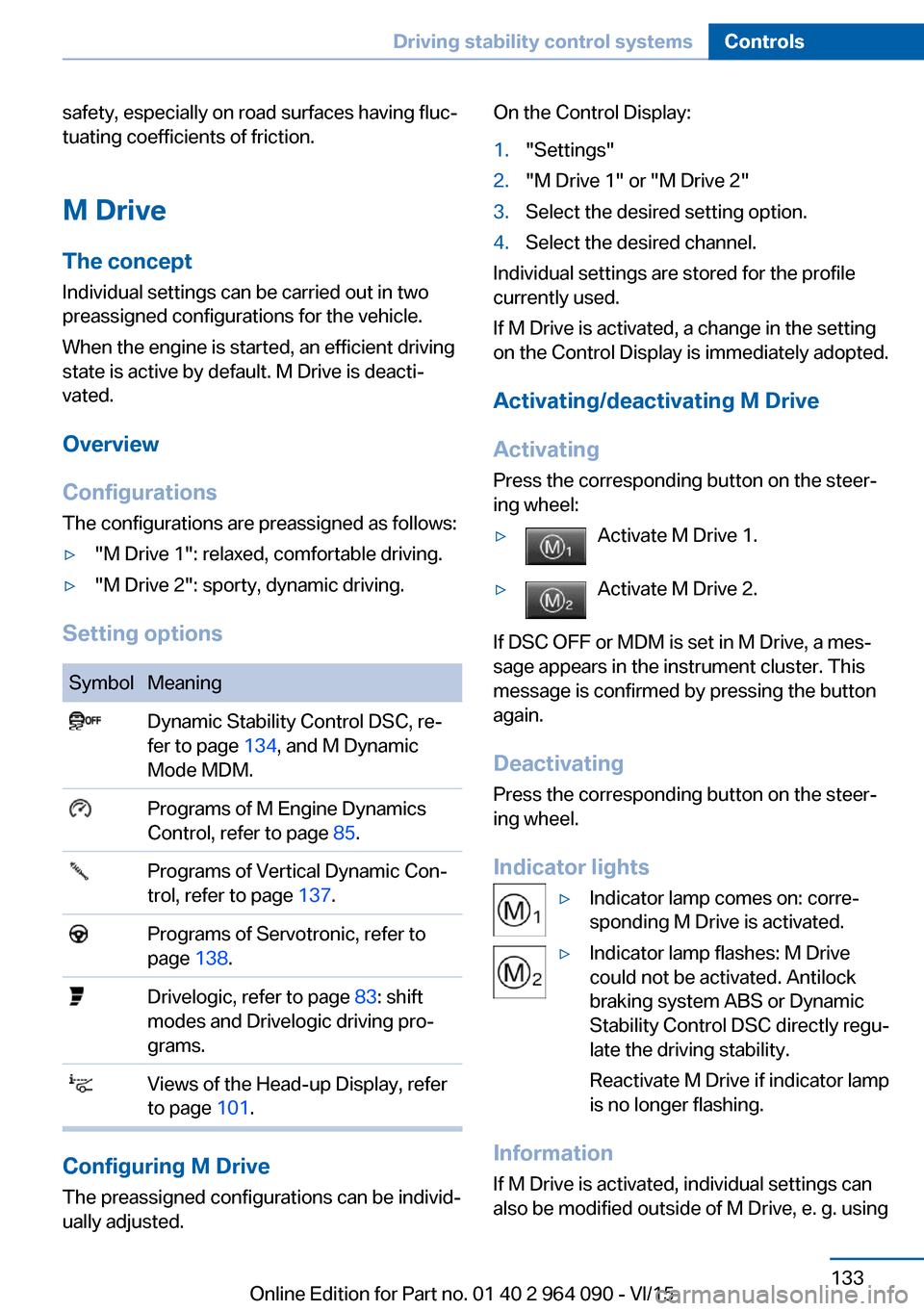
The configurations are preassigned as follows:▷"M Drive 1": relaxed, comfortable driving.▷"M Drive 2": sporty, dynamic driving.
Setting options
SymbolMeaning Dynamic Stability Control DSC, re‐
fer to page 134, and M Dynamic
Mode MDM. Programs of M Engine Dynamics
Control, refer to page 85. Programs of Vertical Dynamic Con‐
trol, refer to page 137. Programs of Servotronic, refer to
page 138. Drivelogic, refer to page 83: shift
modes and Drivelogic driving pro‐
grams. Views of the Head-up Display, refer
to page 101.
Configuring M Drive
The preassigned configurations can be individ‐
ually adjusted.
On the Control Display:1."Settings"2."M Drive 1" or "M Drive 2"3.Select the desired setting option.4.Select the desired channel.
Individual settings are stored for the profile
currently used.
If M Drive is activated, a change in the setting
on the Control Display is immediately adopted.
Activating/deactivating M Drive
Activating Press the corresponding button on the steer‐
ing wheel:
▷Activate M Drive 1.▷Activate M Drive 2.
If DSC OFF or MDM is set in M Drive, a mes‐
sage appears in the instrument cluster. This
message is confirmed by pressing the button
again.
Deactivating Press the corresponding button on the steer‐
ing wheel.
Indicator lights
▷Indicator lamp comes on: corre‐
sponding M Drive is activated.▷Indicator lamp flashes: M Drive
could not be activated. Antilock
braking system ABS or Dynamic
Stability Control DSC directly regu‐
late the driving stability.
Reactivate M Drive if indicator lamp
is no longer flashing.
Information
If M Drive is activated, individual settings can
also be modified outside of M Drive, e. g. using
Seite 133Driving stability control systemsControls133
Online Edition for Part no. 01 40 2 964 090 - VI/15
Page 138 of 255
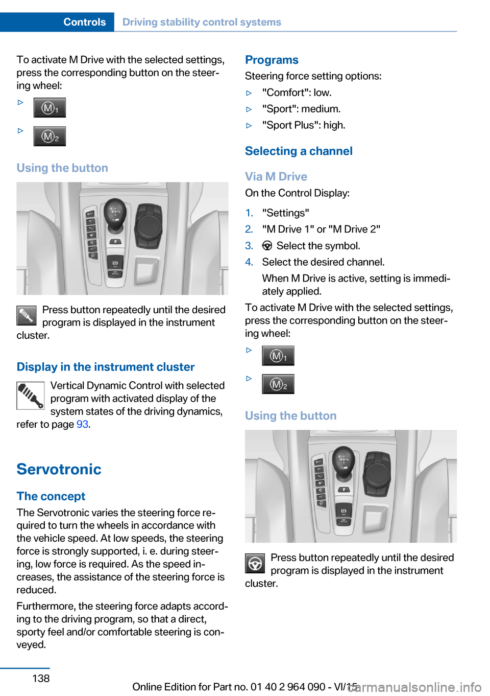
To activate M Drive with the selected settings,
press the corresponding button on the steer‐
ing wheel:▷▷
Using the button
Press button repeatedly until the desired
program is displayed in the instrument
cluster.
Display in the instrument cluster Vertical Dynamic Control with selected
program with activated display of the
system states of the driving dynamics,
refer to page 93.
Servotronic The conceptThe Servotronic varies the steering force re‐
quired to turn the wheels in accordance with
the vehicle speed. At low speeds, the steering
force is strongly supported, i. e. during steer‐
ing, low force is required. As the speed in‐
creases, the assistance of the steering force is
reduced.
Furthermore, the steering force adapts accord‐
ing to the driving program, so that a direct,
sporty feel and/or comfortable steering is con‐
veyed.
Programs
Steering force setting options:▷"Comfort": low.▷"Sport": medium.▷"Sport Plus": high.
Selecting a channel
Via M Drive On the Control Display:
1."Settings"2."M Drive 1" or "M Drive 2"3. Select the symbol.4.Select the desired channel.
When M Drive is active, setting is immedi‐
ately applied.
To activate M Drive with the selected settings,
press the corresponding button on the steer‐
ing wheel:
▷▷
Using the button
Press button repeatedly until the desired
program is displayed in the instrument
cluster.
Seite 138ControlsDriving stability control systems138
Online Edition for Part no. 01 40 2 964 090 - VI/15
Page 139 of 255
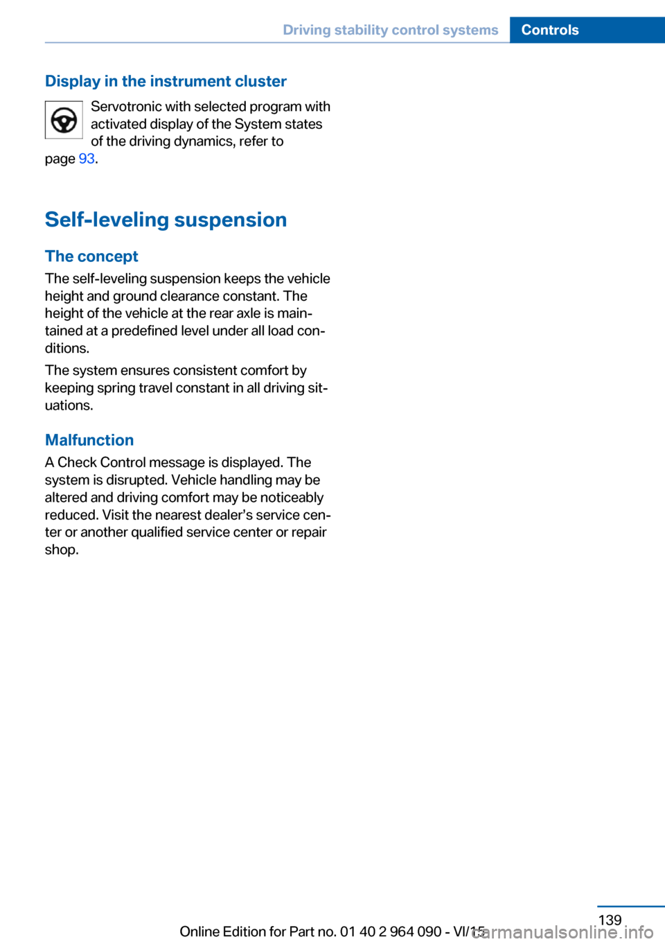
Display in the instrument clusterServotronic with selected program with
activated display of the System states
of the driving dynamics, refer to
page 93.
Self-leveling suspension The concept
The self-leveling suspension keeps the vehicle
height and ground clearance constant. The
height of the vehicle at the rear axle is main‐
tained at a predefined level under all load con‐
ditions.
The system ensures consistent comfort by
keeping spring travel constant in all driving sit‐
uations.
Malfunction A Check Control message is displayed. Thesystem is disrupted. Vehicle handling may be
altered and driving comfort may be noticeably
reduced. Visit the nearest dealer’s service cen‐
ter or another qualified service center or repair
shop.Seite 139Driving stability control systemsControls139
Online Edition for Part no. 01 40 2 964 090 - VI/15
Page 140 of 255
Driving comfortVehicle features and options
This chapter describes all standard, country-
specific and optional features offered with the
series. It also describes features that are not
necessarily available in your car, e. g., due to
the selected options or country versions. This
also applies to safety-related functions and
systems. The respectively applicable country
provisions must be observed when using the
respective features and systems.
Cruise control The concept The system maintains a preset speed via the
buttons on the steering wheel. The system brakes on downhill gradients if engine braking
is insufficient.
General information
Depending on the driving settings, the features
of the cruise control can change in certain
areas.
Information WARNING
The use of the system can lead to an in‐
creased risk of accidents in the following situa‐
tions:▷On winding roads.▷In heavy traffic.▷On slippery roads, in fog, snow or rain, or
on a loose road surface.
There is risk of accidents or risk of property
damage. Only use the system if driving at con‐
stant speed is possible.◀
Overview
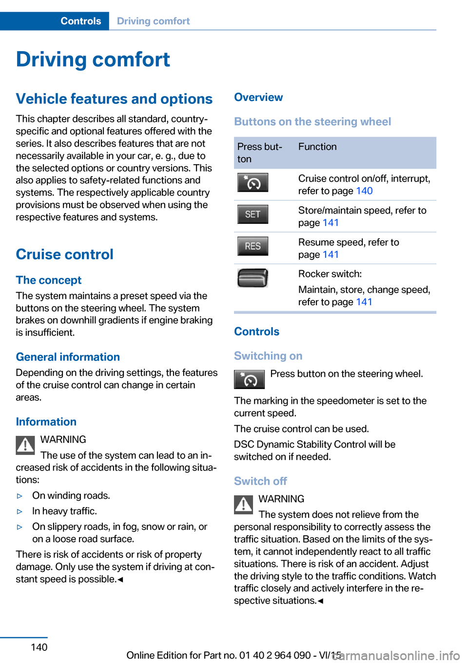
Buttons on the steering wheelPress but‐
tonFunctionCruise control on/off, interrupt,
refer to page 140Store/maintain speed, refer to
page 141Resume speed, refer to
page 141Rocker switch:
Maintain, store, change speed,
refer to page 141
Controls
Switching on Press button on the steering wheel.
The marking in the speedometer is set to the
current speed.
The cruise control can be used.
DSC Dynamic Stability Control will be
switched on if needed.
Switch off WARNING
The system does not relieve from the
personal responsibility to correctly assess the
traffic situation. Based on the limits of the sys‐
tem, it cannot independently react to all traffic
situations. There is risk of an accident. Adjust
the driving style to the traffic conditions. Watch
traffic closely and actively interfere in the re‐
spective situations.◀
Seite 140ControlsDriving comfort140
Online Edition for Part no. 01 40 2 964 090 - VI/15
Page 141 of 255
Press button on the steering wheel.▷If active: press twice.▷If interrupted: press once.
The displays go out. The stored desired speed
is deleted.
Interrupting When active, press the button.
The system is automatically interrupted in the
following situations:
▷When the brakes are applied.▷If selector lever position D is disengaged.▷If MDM is activated or DSC is deactivated.▷When DSC is actively controlling stability.▷If HDC is activated.
Maintaining, storing, and changing the
speed
Information WARNING
The desired speed can be incorrectly ad‐
justed or called up by mistake. There is risk of
an accident. Adjust the desired speed to the
traffic conditions. Watch traffic closely and ac‐
tively interfere in the respective situations.◀
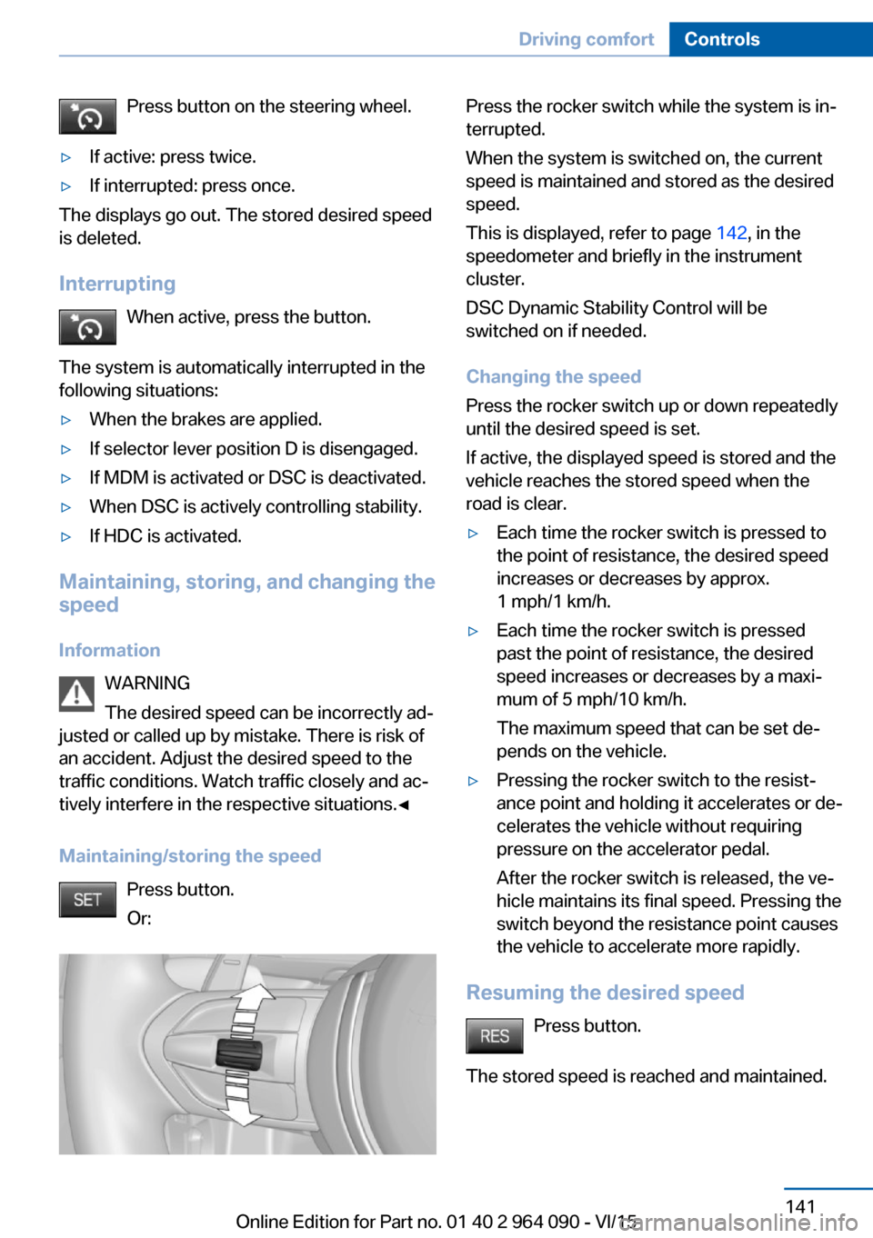
Maintaining/storing the speed Press button.
Or:
Press the rocker switch while the system is in‐
terrupted.
When the system is switched on, the current
speed is maintained and stored as the desired
speed.
This is displayed, refer to page 142, in the
speedometer and briefly in the instrument
cluster.
DSC Dynamic Stability Control will be
switched on if needed.
Changing the speed
Press the rocker switch up or down repeatedly
until the desired speed is set.
If active, the displayed speed is stored and the
vehicle reaches the stored speed when the
road is clear.▷Each time the rocker switch is pressed to
the point of resistance, the desired speed
increases or decreases by approx.
1 mph/1 km/h.▷Each time the rocker switch is pressed
past the point of resistance, the desired
speed increases or decreases by a maxi‐
mum of 5 mph/10 km/h.
The maximum speed that can be set de‐
pends on the vehicle.▷Pressing the rocker switch to the resist‐
ance point and holding it accelerates or de‐
celerates the vehicle without requiring
pressure on the accelerator pedal.
After the rocker switch is released, the ve‐
hicle maintains its final speed. Pressing the
switch beyond the resistance point causes
the vehicle to accelerate more rapidly.
Resuming the desired speed
Press button.
The stored speed is reached and maintained.
Seite 141Driving comfortControls141
Online Edition for Part no. 01 40 2 964 090 - VI/15