2016 BMW X5M service
[x] Cancel search: servicePage 102 of 255

Setting the brightness
The brightness is automatically adjusted to the
ambient brightness.
The basic setting can be adjusted manually.
On the Control Display:1."Settings"2."Head-Up Display"3."Brightness"4.Turn the controller until the desired bright‐
ness is set.5.Press the controller.
When the low beams are activated, the bright‐
ness of the Head-up Display can be addition‐
ally influenced using the instrument lighting.
Settings are stored for the profile currently
used.
Adjusting the height
On the Control Display:
1."Settings"2."Head-Up Display"3."Height"4.Turn the controller until the desired height
is reached.5.Press the controller.
Settings are stored for the profile currently
used.
Setting the rotation
The screen of the Head-up Display can be ro‐
tated around its own axis.
Only set the rotation while the vehicle is sta‐
tionary and the ignition is switched on.
On the Control Display:
1."Settings"2."Head-Up Display"3."Rotation"4.Turn the controller until the desired setting
is selected.5.Press the controller.
Settings are stored for the profile currently
used.
Special windshield
The windshield is part of the system.
The shape of the windshield makes it possible
to display a precise image.
A film in the windshield prevents double im‐
ages from being displayed.
For this reason, it is strongly suggested to
have the special windshield replaced by a
dealer’s service center or another qualified
service center or repair shop.
Shift point indicator
General information
The display is in the Head-up Display.
Shift point indicator in the Head-up
Display
Switching on Shift lights are only shown in the Head-up Dis‐
play in the M view, refer to page 101.
1.Switch on Head-up Display, refer to
page 101.2."Settings"3."Head-Up Display"4."Displayed information"5."M View"Seite 102ControlsDisplays102
Online Edition for Part no. 01 40 2 964 090 - VI/15
Page 110 of 255

Knee airbagThe knee airbag supports the legs in a frontal
impact.
Protective action
Airbags are not triggered in every impact situa‐
tion, e.g., in less severe accidents or rear-end
collisions.
Information for optimum effect of the
airbags
WARNING
If the seat position is incorrect or the de‐
ployment area of the airbags is impacted, the
airbag system cannot protect as intended or
cause additional injuries due to triggering.
There is risk of injuries or danger to life. Ob‐
serve the Information for optimum protective
effect of the airbag system.◀▷Keep at a distance from the airbags.▷Make sure that occupants keep their heads
away from the side airbag.▷Always grasp the steering wheel on the
steering wheel rim. Hold your hands at the
3 o'clock and 9 o'clock positions, to keep
the risk of injury to your hands or arms as
low as possible when the airbag is trig‐
gered.▷Make sure that the front passenger is sit‐
ting correctly, i.e., keeps his or her feet and
legs in the floor area.▷There should be no persons, animals or
objects between an airbag and a person.▷Do not apply adhesive materials to the air‐
bag cover panels, do not cover them or
modify them in any way.▷Dashboard and windshield on the front
passenger side must stay clear - do not at‐
tach adhesive labels or coverings and do
not attach brackets or cables, e. g., for GPS
devices or' mobile phones.▷Do not use the cover of the front airbag on
the front passenger side as a storage area.▷Do not place slip covers, seat cushions or
other objects on the front passenger seat
that are not specifically suited for seats
with integrated side airbags.▷Do not hang pieces of clothing, such as
jackets, over the backrests.▷Never modify either the individual compo‐
nents or the wiring in the airbag system.
This also applies to steering wheel covers,
the dashboard, and the seats.▷Do not remove the airbag system.
Even when you follow all instructions very
closely, injury from contact with the airbags
cannot be ruled out in certain situations.
The ignition and inflation noise may lead to
short-term and, in most cases, temporary
hearing impairment in sensitive individuals.
Warnings and information on the airbags are
also found on the sun visors.
Functional readiness of the airbag
system
Information WARNING
Individual components can be hot after
triggering of the airbag system. There is risk of
injuries. Do not touch individual components.◀
WARNING
Improperly executed work can lead to
failure, malfunction or unintentional triggering
of the airbag system. In the case of a malfunc‐
tion, the airbag system could not trigger as in‐
tended in the event of an accident despite re‐
spective accident severity. There is risk of
injuries or danger to life. Have the airbag sys‐
tem checked, repaired, dismantled and scrap‐
ped by a dealer’s service center or another qualified service center or repair shop.◀
Seite 110ControlsSafety110
Online Edition for Part no. 01 40 2 964 090 - VI/15
Page 114 of 255

Required tire inflation pressure check
message
A Check Control message is displayed in the
following situations▷The system has detected a wheel change,
but no reset was done.▷Inflation was not carried out according to
specifications.▷The tire inflation pressure has fallen below
the level of the last confirmation.
In this case:
▷Check the tire pressure and correct as
needed.▷Carry out a reset of the system after a tire
change.
System limits
The system does not function properly if a re‐
set has not been carried out, e.g., a flat tire is
reported though tire inflation pressures are
correct.
The tire inflation pressure depends on the
tire's temperature. Driving or exposure to the
sun will increase the tire's temperature, thus
increasing the tire inflation pressure. The tire
inflation pressure is reduced when the tire
temperature falls again. These circumstances
may cause a warning when temperatures fall
very sharply.
The system cannot indicate sudden serious
tire damage caused by external circumstances.
Malfunction The yellow warning lamp flashes and
then lights up continuously. A Check
Control message is displayed. No flat
tire or loss of tire inflation pressure can be de‐
tected.
Examples and recommendations in the follow‐
ing situations:
▷A wheel without TPM electronics is
mounted: Have it checked by a dealer’sservice center or another qualified service
center or repair shop as needed.▷Malfunction: Have system checked by a
dealer’s service center or another qualified
service center or repair shop.▷TPM was unable to complete the reset.
Reset the system again.▷Interference through systems or devices
with the same radio frequency: After leav‐
ing the area of the interference, the system
automatically becomes active again.
Declaration according to NHTSA/
FMVSS 138 Tire Pressure Monitoring
System
Each tire, including the spare (if provided)
should be checked monthly when cold and in‐
flated to the inflation pressure recommended
by the vehicle manufacturer on the vehicle
placard or tire inflation pressure label. (If your
vehicle has tires of a different size than the size
indicated on the vehicle placard or tire inflation
pressure label, you should determine the
proper tire inflation pressure for those tires.)
As an added safety feature, your vehicle has
been equipped with a tire pressure monitoring
system (TPMS) that illuminates a low tire pres‐
sure telltale when one or more of your tires is
significantly under-inflated. Accordingly, when
the low tire pressure telltale illuminates, you
should stop and check your tires as soon as
possible, and inflate them to the proper pres‐
sure. Driving on a significantly under-inflated
tire causes the tire to overheat and can lead to
tire failure. Under-inflation also reduces fuel ef‐
ficiency and tire tread life, and may affect the
vehicle's handling and stopping ability. Please
note that the TPMS is not a substitute for
proper tire maintenance, and it is the driver's
responsibility to maintain correct tire pressure,
even if under-inflation has not reached the
level to trigger illumination of the TPMS low
tire pressure telltale. Your vehicle has also
been equipped with a TPMS malfunction indi‐
cator to indicate when the system is not oper‐
Seite 114ControlsSafety114
Online Edition for Part no. 01 40 2 964 090 - VI/15
Page 139 of 255

Display in the instrument clusterServotronic with selected program with
activated display of the System states
of the driving dynamics, refer to
page 93.
Self-leveling suspension The concept
The self-leveling suspension keeps the vehicle
height and ground clearance constant. The
height of the vehicle at the rear axle is main‐
tained at a predefined level under all load con‐
ditions.
The system ensures consistent comfort by
keeping spring travel constant in all driving sit‐
uations.
Malfunction A Check Control message is displayed. Thesystem is disrupted. Vehicle handling may be
altered and driving comfort may be noticeably
reduced. Visit the nearest dealer’s service cen‐
ter or another qualified service center or repair
shop.Seite 139Driving stability control systemsControls139
Online Edition for Part no. 01 40 2 964 090 - VI/15
Page 162 of 255

Interior equipmentVehicle features and optionsThis chapter describes all standard, country-
specific and optional features offered with the
series. It also describes features that are not
necessarily available in your car, e. g., due to
the selected options or country versions. This
also applies to safety-related functions and
systems. The respectively applicable country
provisions must be observed when using the
respective features and systems.
Universal Integrated Remote Control
The concept The universal garage door opener can operate
up to 3 functions of remote-controlled sys‐
tems such as garage door drives or lighting
systems. The universal garage door opener re‐
places up to 3 different hand-held transmitters.
To operate the remote control, the buttons on
the interior rearview mirror must be program‐
med with the desired functions. The hand-held
transmitter for the particular system is required
in order to program the remote control.
Before selling the vehicle, delete the stored
functions for the sake of security.
Information WARNING
Body parts can be jammed when operat‐
ing remote-controlled systems, e.g. the garage
door, using the universal garage door opener.
There is risk of injuries or risk of property dam‐
age. Make sure that the area of movement of
the respective system is clear during program‐
ming and operation. Also follow the safety in‐
structions of the hand-held transmitter.◀Compatibility
If this symbol is printed on the packag‐
ing or in the instructions of the system
to be controlled, the system is gener‐
ally compatible with the universal garage door opener.
If you have any questions, please contact:▷A dealer’s service center or another quali‐
fied service center or repair shop.▷www.homelink.com on the Internet.
HomeLink is a registered trademark of Gentex
Corporation.
Controls on the interior rearview
mirror
▷LED, arrow 1.▷Buttons, arrow 2.▷The hand-held transmitter, arrow 3, is re‐
quired for programming.
Programming
General information
1.Switch on the ignition.2.Initial setup:
Press and hold the left and right button on
the interior rearview mirror simultaneously
for approximately 20 seconds until the LED
on the interior rearview mirror flashes. ThisSeite 162ControlsInterior equipment162
Online Edition for Part no. 01 40 2 964 090 - VI/15
Page 168 of 255

The highest cooling power is active when
two LEDs are lit.
If the cooler was switched on the last time the
ignition was switched on, it will likewise be
switched on the next time the ignition is
switched on.
Switch off
Press button repeatedly until the LEDs go out.
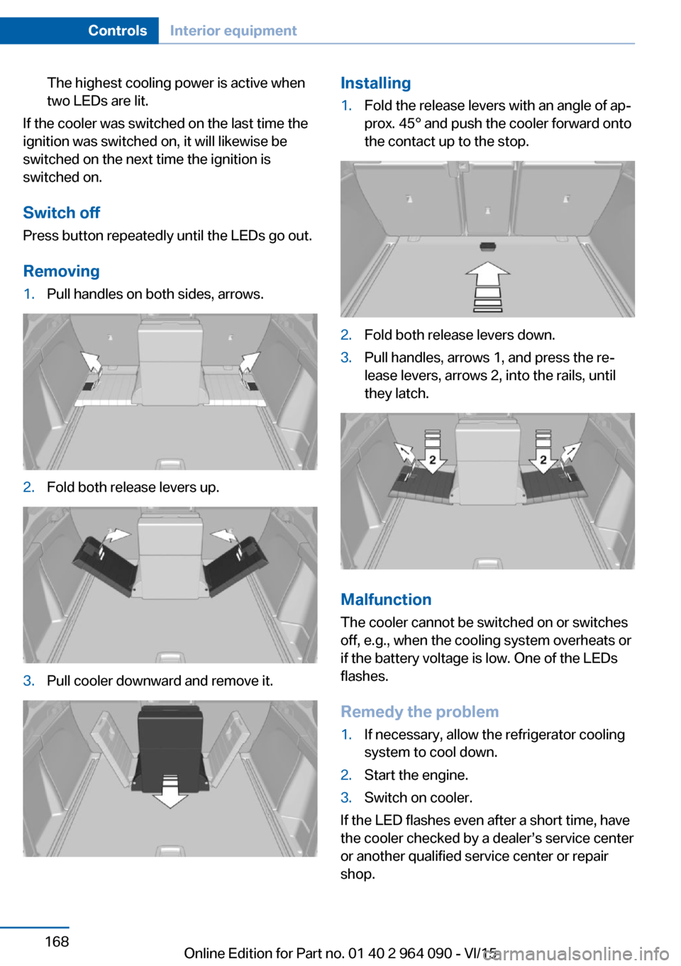
Removing
1.Pull handles on both sides, arrows.2.Fold both release levers up.3.Pull cooler downward and remove it.Installing1.Fold the release levers with an angle of ap‐
prox. 45° and push the cooler forward onto
the contact up to the stop.2.Fold both release levers down.3.Pull handles, arrows 1, and press the re‐
lease levers, arrows 2, into the rails, until
they latch.
Malfunction
The cooler cannot be switched on or switches
off, e.g., when the cooling system overheats or
if the battery voltage is low. One of the LEDs
flashes.
Remedy the problem
1.If necessary, allow the refrigerator cooling
system to cool down.2.Start the engine.3.Switch on cooler.
If the LED flashes even after a short time, have
the cooler checked by a dealer’s service center
or another qualified service center or repair
shop.
Seite 168ControlsInterior equipment168
Online Edition for Part no. 01 40 2 964 090 - VI/15
Page 182 of 255

BMW X5 M and BMW X6 M TechnologyVehicle features and options
This chapter describes all standard, country-
specific and optional features offered with the
series. It also describes features that are not
necessarily available in your car, e. g., due to
the selected options or country versions. This
also applies to safety-related functions and
systems. The respectively applicable country
provisions must be observed when using the
respective features and systems.
V8 high-performance engine With a 4.4 liter displacement, the V8 high-per‐
formance engine generates a maximum power
of 567 hp and a maximum torque of 553 lb ft/750 Nm. With its spontaneous response be‐
havior, a speed range of wide utility results.
The maximum engine speed is 6,800 rpm and
is electronically controlled. Because of the
high engine dynamics, the maximum engine
speed with the vehicle stationary is reduced.
Warm-up
During the engine warm-up phase, the V8 high-performance engine has a somewhat
rougher running behavior because of the emis‐
sion controls.
When the engine is cold, the exhaust system
has a slightly metallic undertone due to the na‐
ture of the system.
For more information about the warm-up pro‐
cedure: Engine speed, refer to page 91, and
engine oil temperature, refer to page 91.
Compound brake
The high-performance braking system has
perforated compound brake discs.Because of particular structural characteristics,
there may be operation-related noises during
braking. However, this has no effect on per‐
formance, operational reliability and reliability
of the brake.
Correct brakingTo keep the brake system in optimum condi‐
tion, it is expedient to apply them at regular in‐
tervals corresponding to the vehicle character.
Drivetrain
The xDrive all-wheel-drive system establishes
a permanent variable torque distribution to the
front and rear axles. The combination of xDrive and Dynamic Performance Control in this vehi‐cle ensures a high degree of driving dynamics
typical for BMW M.
With the activation of the M Dynamic mode,
dynamics and steering precision can be in‐
creased even more in all speed ranges.
Driving on racetracks
Requirements Before driving on a racetrack:▷Participation in BMW Driver Experience
Training.▷Check engine oil fill level and replenish as
necessary.▷Have vehicle checked by a dealer's service
center or another qualified service center
or repair shop.
Information
Racetrack operation leads to increased wear.
The vehicle is not designed for motorsports
Seite 182Driving tipsBMW X5 M and BMW X6 M Technology182
Online Edition for Part no. 01 40 2 964 090 - VI/15
Page 183 of 255

competitive use. This wear is not covered by
the warranty.
The standard brake linings and the wear indi‐
cators are not designed for racetrack opera‐
tion. Additional information and advice is avail‐
able from a dealer's service center or another
qualified service center or repair shop.Seite 183BMW X5 M and BMW X6 M TechnologyDriving tips183
Online Edition for Part no. 01 40 2 964 090 - VI/15