2016 BMW X5 XDRIVE50I ignition
[x] Cancel search: ignitionPage 180 of 275

The highest cooling power is active when
two LEDs are lit.
If the cooler was switched on the last time the
ignition was switched on, it will likewise be
switched on the next time the ignition is
switched on.
Switch off
Press button repeatedly until the LEDs go out.
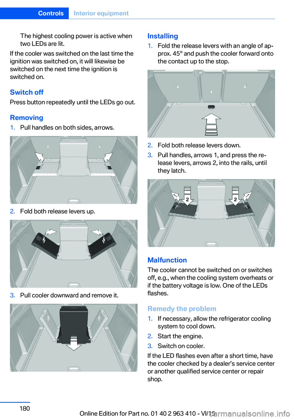
Removing
1.Pull handles on both sides, arrows.2.Fold both release levers up.3.Pull cooler downward and remove it.Installing1.Fold the release levers with an angle of ap‐
prox. 45° and push the cooler forward onto
the contact up to the stop.2.Fold both release levers down.3.Pull handles, arrows 1, and press the re‐
lease levers, arrows 2, into the rails, until
they latch.
Malfunction
The cooler cannot be switched on or switches
off, e.g., when the cooling system overheats or
if the battery voltage is low. One of the LEDs
flashes.
Remedy the problem
1.If necessary, allow the refrigerator cooling
system to cool down.2.Start the engine.3.Switch on cooler.
If the LED flashes even after a short time, have
the cooler checked by a dealer’s service center
or another qualified service center or repair
shop.
Seite 180ControlsInterior equipment180
Online Edition for Part no. 01 40 2 963 410 - VI/15
Page 213 of 275

haust fluid. Do not swallow any Diesel exhaust
fluid. Keep children away from Diesel exhaust
fluids.◀
WARNING
Operating materials, e.g. oils, greases,
coolants, fuels, can contain harmful ingredi‐
ents. There is risk of injuries or danger to life.
Observe the instructions on the containers.
Avoid the contact of articles of clothing, skin or
eyes with operating materials. Do not refill op‐
erating materials into different bottles. Store
operating materials out of reach of children.◀
CAUTION
The Diesel exhaust fluid ingredients are
very aggressive. There is risk of property dam‐
age. Avoid contact of Diesel exhaust fluid with
surfaces of the vehicle.◀
Suitable Diesel exhaust fluid▷Recommended: BMW Diesel Exhaust
Fluid. With this bottle and its special
adapter, Diesel exhaust fluid can be replen‐
ished simply and safely.▷Alternatively recommended: NOx Diesel
exhaust fluid AUS 32.
Diesel exhaust fluid can be purchased at a
dealer’s service center or another qualified
service center or repair shop.
Refill quantity
When the Reserve display starts, add at least
3 bottles of Diesel exhaust fluid.
This corresponds to approx. 1.5 US gal/6 liters.
Tank for Diesel exhaust fluid
The fuel cap for the Diesel exhaust fluid is lo‐
cated in the engine compartment.
Adding the Diesel exhaust fluid
Add the Diesel exhaust fluid when the ignition
is switched on.
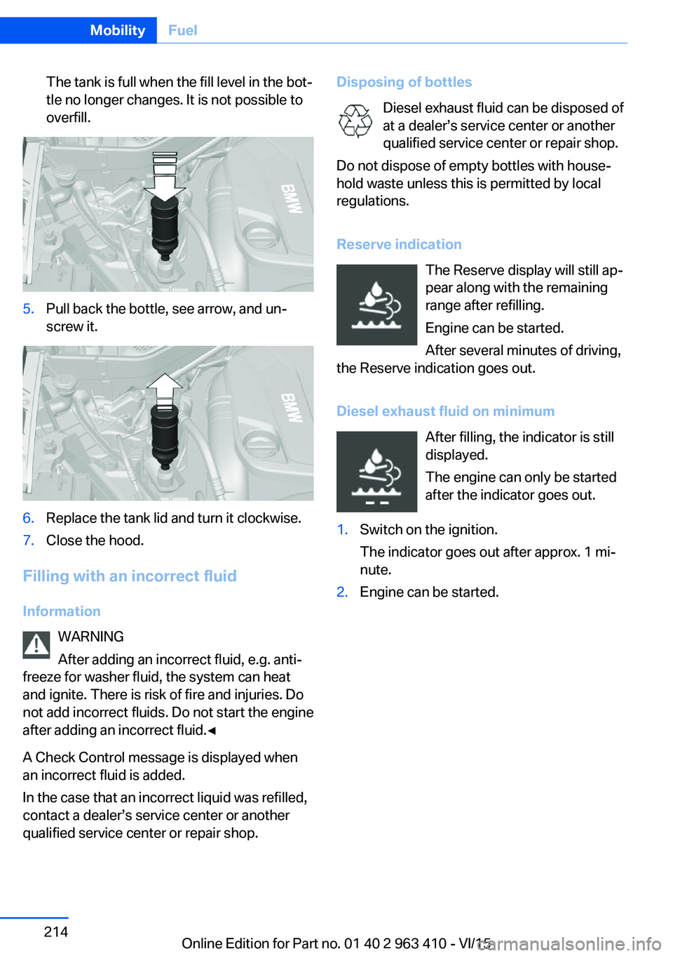
1.Open the hood, refer to page 230.2.Turn the tank lid counterclockwise and re‐
move.3.Place the bottle on it and turn it as far as it
will go, see arrow.4.Press the bottle down, see arrow.
The vehicle tank will be filled.Seite 213FuelMobility213
Online Edition for Part no. 01 40 2 963 410 - VI/15
Page 214 of 275

The tank is full when the fill level in the bot‐
tle no longer changes. It is not possible to
overfill.5.Pull back the bottle, see arrow, and un‐
screw it.6.Replace the tank lid and turn it clockwise.7.Close the hood.
Filling with an incorrect fluid
Information WARNING
After adding an incorrect fluid, e.g. anti‐
freeze for washer fluid, the system can heat
and ignite. There is risk of fire and injuries. Do
not add incorrect fluids. Do not start the engine
after adding an incorrect fluid.◀
A Check Control message is displayed when
an incorrect fluid is added.
In the case that an incorrect liquid was refilled,
contact a dealer’s service center or another
qualified service center or repair shop.
Disposing of bottles
Diesel exhaust fluid can be disposed of
at a dealer’s service center or another qualified service center or repair shop.
Do not dispose of empty bottles with house‐
hold waste unless this is permitted by local
regulations.
Reserve indication The Reserve display will still ap‐
pear along with the remaining
range after refilling.
Engine can be started.
After several minutes of driving,
the Reserve indication goes out.
Diesel exhaust fluid on minimum After filling, the indicator is still
displayed.
The engine can only be started
after the indicator goes out.1.Switch on the ignition.
The indicator goes out after approx. 1 mi‐
nute.2.Engine can be started.Seite 214MobilityFuel214
Online Edition for Part no. 01 40 2 963 410 - VI/15
Page 227 of 275

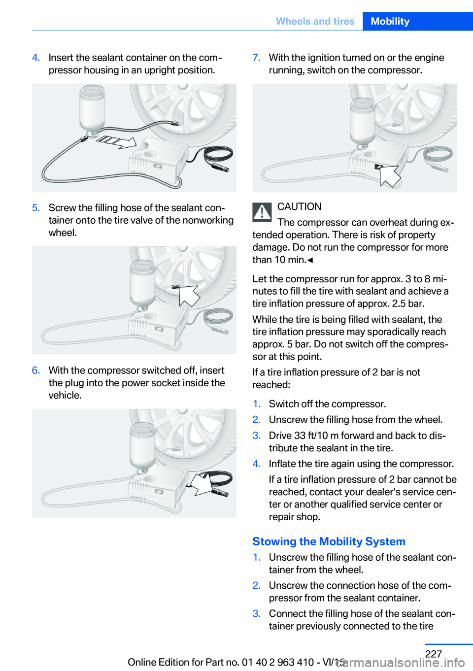
4.Insert the sealant container on the com‐
pressor housing in an upright position.5.Screw the filling hose of the sealant con‐
tainer onto the tire valve of the nonworking
wheel.6.With the compressor switched off, insert
the plug into the power socket inside the
vehicle.7.With the ignition turned on or the engine
running, switch on the compressor.
CAUTION
The compressor can overheat during ex‐
tended operation. There is risk of property
damage. Do not run the compressor for more
than 10 min.◀
Let the compressor run for approx. 3 to 8 mi‐
nutes to fill the tire with sealant and achieve a
tire inflation pressure of approx. 2.5 bar.
While the tire is being filled with sealant, the
tire inflation pressure may sporadically reach
approx. 5 bar. Do not switch off the compres‐
sor at this point.
If a tire inflation pressure of 2 bar is not
reached:
1.Switch off the compressor.2.Unscrew the filling hose from the wheel.3.Drive 33 ft/10 m forward and back to dis‐
tribute the sealant in the tire.4.Inflate the tire again using the compressor.
If a tire inflation pressure of 2 bar cannot be
reached, contact your dealer’s service cen‐
ter or another qualified service center or
repair shop.
Stowing the Mobility System
1.Unscrew the filling hose of the sealant con‐
tainer from the wheel.2.Unscrew the connection hose of the com‐
pressor from the sealant container.3.Connect the filling hose of the sealant con‐
tainer previously connected to the tireSeite 227Wheels and tiresMobility227
Online Edition for Part no. 01 40 2 963 410 - VI/15
Page 228 of 275

valve with the available connector on the
sealant container.
This prevents leftover sealant from escap‐
ing from the container.4.Wrap the empty sealant container in suita‐
ble material to avoid dirtying the trunk.5.Stow the Mobility System back in the vehi‐
cle.
Distributing the sealant
Immediately drive approx. 5 miles/10 km to en‐
sure that the sealant is evenly distributed in the
tire.
Do not exceed a speed of 50 mph/80 km/h.
If possible, do not drive at speeds less than
12 mph/20 km/h.
To correct the tire inflation pressure
1.Stop at a suitable location.2.Screw the connection hose of the com‐
pressor directly onto the tire valve stem.3.Insert the connector into the power socket
inside the vehicle.4.Correct the tire inflation pressure to
2.5 bar.▷Increase pressure: with the ignition
turned on or the engine running, switch
on the compressor.▷To reduce the pressure: press the but‐
ton on the compressor.
Continuing the trip
Do not exceed the maximum permissible
speed of 50 mph/80 km/h.
Reinitialize the Flat Tire Monitor.
Reinitialize the Tire Pressure Monitor.
Replace the nonworking tire and the sealant
container of the Mobility System as soon as
possible.
Snow chains
Fine-link snow chains The manufacturer of your vehicle recommends
use of fine-link snow chains. Certain types of
fine-link snow chains have been tested by the
manufacturer of the vehicle and recommended
as road-safe and suitable.
Information regarding suitable snow chains is
available from a dealer’s service center or an‐
other qualified service center or repair shop.
Use
Use only in pairs on the rear wheels, equipped
with the tires of the following size:▷255/55 R 18.▷255/50 R 19.
Follow the snow chain manufacturer's instruc‐
tions.
Make sure that the snow chains are always
sufficiently tight. Retighten as needed accord‐
ing to the chain manufacturer's instructions.
Do not initialize the Flat Tire Monitor after
mounting snow chains, as doing so may result
in incorrect readings.
Do not initialize the Tire Pressure Monitor after
mounting snow chains, as doing so may result
in incorrect readings.
When driving with snow chains, briefly activate
Dynamic Traction Control if needed.
Maximum speed with snow chains Do not exceed a speed of 30 mph/50 km/hwhen using snow chains.
Seite 228MobilityWheels and tires228
Online Edition for Part no. 01 40 2 963 410 - VI/15
Page 233 of 275

Different messages appear on the display de‐
pending on the engine oil level. Pay attention
to these messages.
If the engine oil level is too low, within the next
125 miles/200 km Add engine oil, refer to
page 233.
Detailed measurement
The concept In the detailed measurement the engine oil
level is checked and displayed via a scale.
Gasoline engine:
If the engine oil level reaches the minimum
level, a check control message is displayed.
Diesel engine:
If the engine oil level reaches the minimum
level or an overfilling is detected, a check con‐
trol message is displayed.
During the measurement, the idle speed is in‐
creased somewhat.
Requirements▷Vehicle is on level road.▷Steptronic transmission: selector lever in
selector lever position N or P and accelera‐
tor pedal not depressed.▷Engine is running and is at operating tem‐
perature.
Performing a detailed measurement
In order to perform a detailed measurement of
the engine oil level:
1."Vehicle info"2."Vehicle status"3. "Measure engine oil level"4."Start measurement"
The engine oil level is checked and displayed
via a scale.
Time: approx. 1 minute.
Adding engine oil
Information CAUTION
A too low engine oil level causes engine
damage. There is risk of property damage.
Add engine oil within the next
125 miles/200 km.◀
CAUTION
Too much engine oil can damage the en‐
gine or the catalytic converter. There is risk of
property damage. Do not add too much engine
oil. Have too much engine oil siphoned off by a
dealer’s service center or another qualified
service center or repair shop.◀
WARNING
Operating materials, e.g. oils, greases,
coolants, fuels, can contain harmful ingredi‐
ents. There is risk of injuries or danger to life.
Observe the instructions on the containers.
Avoid the contact of articles of clothing, skin or
eyes with operating materials. Do not refill op‐
erating materials into different bottles. Store
operating materials out of reach of children.◀
General information
Only add engine oil when the message is dis‐
played in the instrument cluster. The quantity
to be added is indicated in the message dis‐
played in the instrument cluster.
Switch off the ignition and safely park the vehi‐
cle before engine oil is added.
Overview
The oil filler neck is located in the engine com‐
partment, refer to page 229.
Opening the oil filler neck1.Opening the hood, refer to page 230Seite 233Engine oilMobility233
Online Edition for Part no. 01 40 2 963 410 - VI/15
Page 255 of 275

Before driving into a car wash
In order to ensure that the vehicle can roll in a
car wash, take the following steps:1.Drive into the car wash.2.Engage selector lever position N.3.Deactivating Automatic Hold, refer to
page 75.4.Release the parking brake.5.Switch the engine off.
In this way, the ignition remains switched
on, and a Check-Control message is dis‐
played.
CAUTION
Selector lever position P is automati‐
cally engaged when the ignition is
switched off. There is risk of property dam‐
age. Do not switch ignition off in car
washes.◀
The vehicle cannot be locked from the outside
when in selector lever position N. A signal
sounds when an attempt is made to lock the
vehicle.
To start the engine:
1.Depress the brake pedal.2.Press the Start/Stop button.
Pressing the Start/Stop button without step‐
ping on the brake turns the ignition off.
Selector lever positionSelector lever position P is engaged automati‐
cally:
▷When the ignition is switched off.▷After approx. 15 minutes.
Headlights
▷Do not rub dry and do not use abrasive or
acidic cleansers.▷Soak areas that have been dirtied e. g.,
from insects, with shampoo and wash off
with water.▷Thaw ice with de-icing spray; do not use an
ice scraper.
After washing the vehicle
After washing the vehicle, apply the brakes
briefly to dry them; otherwise, braking action
can be reduced and corrosion of the brake
discs can occur.
Completely remove all residues on the win‐
dows, to minimize loss of visibility due to
smearing and to reduce wiper noises and
wiper blade wear.
Vehicle care
Car care products The manufacturer of your vehicle recommends
using car care and cleaning products from
BMW.
WARNING
Cleansers can contain substances that
are dangerous and harmful to your health.
There is risk of injuries. When cleaning the in‐
terior, open the doors or windows. Only use
products intended for cleaning vehicles. Fol‐
low the instructions on the container.◀
Vehicle paint
Regular care contributes to driving safety and
value retention. Environmental influences in
areas with elevated air pollution or natural con‐
taminants, such as tree resin or pollen can af‐
fect the vehicle's paintwork. Tailor the fre‐
quency and extent of your car care to these
influences.
Aggressive substances such as spilled fuel, oil,
grease or bird droppings, must be removed im‐
mediately to prevent the finish from being al‐
tered or discolored.
Leather care
Remove dust from the leather often, using a
cloth or vacuum cleaner.
Seite 255CareMobility255
Online Edition for Part no. 01 40 2 963 410 - VI/15
Page 268 of 275

Glass sunroof, refer to Panor‐amic glass sunroof 49
Glove compartment 183
Gross vehicle weight, ap‐ proved 261
H
Handbrake, see Parking brake 73
Hand-held transmitter, alter‐ nating code 175
Hazard warning flashers 248
HDC Hill Descent Con‐ trol 140
Head airbags 109
Headlight control, auto‐ matic 105
Headlight courtesy delay fea‐ ture 105
Headlight flasher 77
Headlight glass 242
Headlights 242
Headlights, care 255
Head restraints 52
Head restraints, front 58
Head restraints, rear 59
Head-up Display 101
Head-up Display, care 257
Heavy cargo, stowing 197
High-beam Assistant 106
High beams 77
High beams/low beams, see High-beam Assistant 106
Hill Descent Control HDC 140
Hills 194
Hill start assistant, see Drive- off assistant 137
Holder for beverages 186
Homepage 6
Hood 230
Horn 14
Hot exhaust system 193
HUD Head-up Display 101
Hydroplaning 193 I
Ice warning, see External temperature warning 93
Icy roads, see External tem‐ perature warning 93
Identification marks, tires 221
Identification number, see ve‐ hicle identification num‐
ber 10
iDrive 18
Ignition key, see Remote con‐ trol 34
Ignition off 69
Ignition on 69
Indication of a flat tire 113 , 117
Indicator and alarm lamps, see Check Control 89
Indicator lamp, see Check Control 89
Individual air distribution 169
Individual settings, see Per‐ sonal Profile 35
Inflation pressure, tires 215
Inflation pressure warning FTM, tires 116
Info display, refer to On- Board computer 98
Information 6
Initialize, Tire Pressure Moni‐ tor TPM 113
Initializing, Flat Tire Monitor FTM 116
Instrument cluster 85
Instrument cluster, electronic displays 85
Instrument display, multifunc‐ tional 86
Instrument lighting 108
Integrated key 34
Integrated Owner's Manual in the vehicle 29
Intelligent Emergency Re‐ quest 248
Intelligent Safety 118 Intensity, AUTO pro‐
gram 169
Interior equipment 174
Interior lights 108
Interior lights during unlock‐ ing 37
Interior lights with the vehicle locked 38
Interior motion sensor 46
Interior rearview mirror, auto‐ matic dimming feature 63
Internet page 6
Interval display, service re‐ quirements 95
Interval mode 78
J
Jacking points for the vehicle jack 244
Joystick, Steptronic transmis‐ sion 81
Jump-starting 249
K
Key/remote control 34
Keyless Go, see Comfort Ac‐ cess 43
Key Memory, see Personal Profile 35
Kickdown, Steptronic trans‐ mission 81
Knee airbag 110
L Label on recommended tires 224
Lamp in the exterior mirror, see Active Blind Spot De‐
tection 133
Lamp replacement 241
Lamp replacement, front 242
Lamp replacement, rear 244
Lane departure warning 131 Seite 268ReferenceEverything from A to Z268
Online Edition for Part no. 01 40 2 963 410 - VI/15