2016 BMW X5 XDRIVE50I tow
[x] Cancel search: towPage 227 of 275
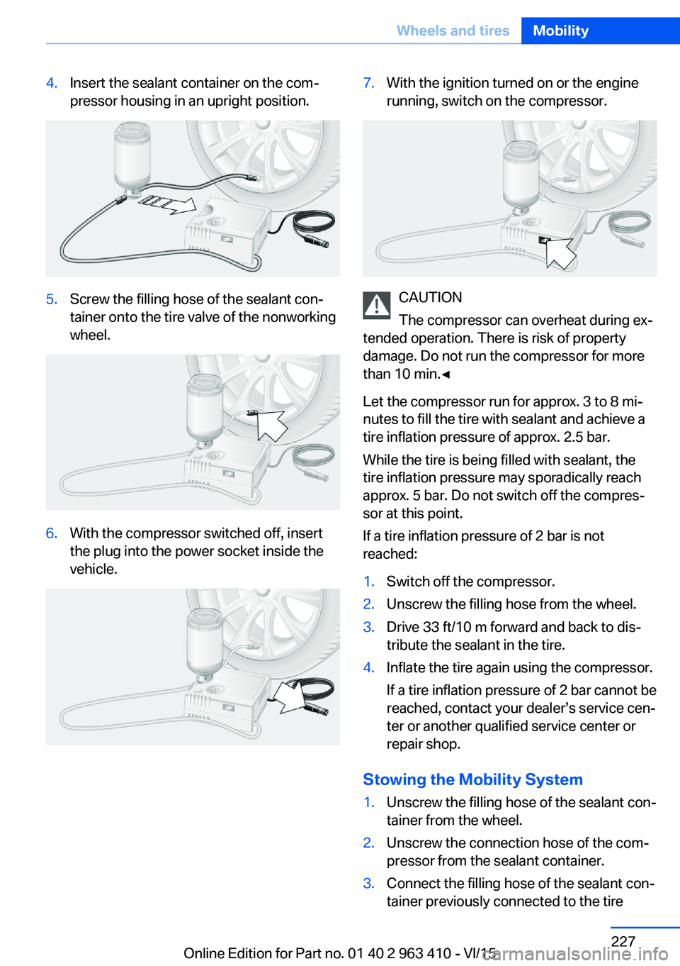
4.Insert the sealant container on the com‐
pressor housing in an upright position.5.Screw the filling hose of the sealant con‐
tainer onto the tire valve of the nonworking
wheel.6.With the compressor switched off, insert
the plug into the power socket inside the
vehicle.7.With the ignition turned on or the engine
running, switch on the compressor.
CAUTION
The compressor can overheat during ex‐
tended operation. There is risk of property
damage. Do not run the compressor for more
than 10 min.◀
Let the compressor run for approx. 3 to 8 mi‐
nutes to fill the tire with sealant and achieve a
tire inflation pressure of approx. 2.5 bar.
While the tire is being filled with sealant, the
tire inflation pressure may sporadically reach
approx. 5 bar. Do not switch off the compres‐
sor at this point.
If a tire inflation pressure of 2 bar is not
reached:
1.Switch off the compressor.2.Unscrew the filling hose from the wheel.3.Drive 33 ft/10 m forward and back to dis‐
tribute the sealant in the tire.4.Inflate the tire again using the compressor.
If a tire inflation pressure of 2 bar cannot be
reached, contact your dealer’s service cen‐
ter or another qualified service center or
repair shop.
Stowing the Mobility System
1.Unscrew the filling hose of the sealant con‐
tainer from the wheel.2.Unscrew the connection hose of the com‐
pressor from the sealant container.3.Connect the filling hose of the sealant con‐
tainer previously connected to the tireSeite 227Wheels and tiresMobility227
Online Edition for Part no. 01 40 2 963 410 - VI/15
Page 228 of 275

valve with the available connector on the
sealant container.
This prevents leftover sealant from escap‐
ing from the container.4.Wrap the empty sealant container in suita‐
ble material to avoid dirtying the trunk.5.Stow the Mobility System back in the vehi‐
cle.
Distributing the sealant
Immediately drive approx. 5 miles/10 km to en‐
sure that the sealant is evenly distributed in the
tire.
Do not exceed a speed of 50 mph/80 km/h.
If possible, do not drive at speeds less than
12 mph/20 km/h.
To correct the tire inflation pressure
1.Stop at a suitable location.2.Screw the connection hose of the com‐
pressor directly onto the tire valve stem.3.Insert the connector into the power socket
inside the vehicle.4.Correct the tire inflation pressure to
2.5 bar.▷Increase pressure: with the ignition
turned on or the engine running, switch
on the compressor.▷To reduce the pressure: press the but‐
ton on the compressor.
Continuing the trip
Do not exceed the maximum permissible
speed of 50 mph/80 km/h.
Reinitialize the Flat Tire Monitor.
Reinitialize the Tire Pressure Monitor.
Replace the nonworking tire and the sealant
container of the Mobility System as soon as
possible.
Snow chains
Fine-link snow chains The manufacturer of your vehicle recommends
use of fine-link snow chains. Certain types of
fine-link snow chains have been tested by the
manufacturer of the vehicle and recommended
as road-safe and suitable.
Information regarding suitable snow chains is
available from a dealer’s service center or an‐
other qualified service center or repair shop.
Use
Use only in pairs on the rear wheels, equipped
with the tires of the following size:▷255/55 R 18.▷255/50 R 19.
Follow the snow chain manufacturer's instruc‐
tions.
Make sure that the snow chains are always
sufficiently tight. Retighten as needed accord‐
ing to the chain manufacturer's instructions.
Do not initialize the Flat Tire Monitor after
mounting snow chains, as doing so may result
in incorrect readings.
Do not initialize the Tire Pressure Monitor after
mounting snow chains, as doing so may result
in incorrect readings.
When driving with snow chains, briefly activate
Dynamic Traction Control if needed.
Maximum speed with snow chains Do not exceed a speed of 30 mph/50 km/hwhen using snow chains.
Seite 228MobilityWheels and tires228
Online Edition for Part no. 01 40 2 963 410 - VI/15
Page 237 of 275

Adding1.Let the engine cool.2.Turn the lid of the coolant reservoir slightly
counterclockwise to allow any excess
pressure to dissipate, then open it.3.If the coolant is low, slowly add coolant up
to the specified level; do not overfill.4.Turn the lid until there is an audible click.
The arrows on the coolant reservoir and
the lid must point towards one another.5.Have the cause of the coolant loss elimi‐
nated as soon as possible.
Disposal
Comply with the relevant environmen‐
tal protection regulations when dispos‐
ing of coolant and coolant additives.
Seite 237CoolantMobility237
Online Edition for Part no. 01 40 2 963 410 - VI/15
Page 243 of 275

The parking lights and daylight running lights
are made using LED technology.
Contact a dealer’s service center or another
qualified service center or repair shop in the
event of a malfunction.
LED headlights With LED headlights, all front lights and side
indicators are designed with LED technology.
If an LED fails, switch on the front fog lights and continue the trip with great care. Comply
with local regulations.
Contact a dealer’s service center or another
qualified service center or repair shop in the
event of a malfunction.
Turn signal
Information
Follow general instructions, refer to page 241.
Replacement
21-watt bulb, PY 21W.1.Opening the hood, refer to page 2302.Unscrew the lid counterclockwise and re‐
move it carefully.
The bulb is attached to the lid.3.Turn the bulb clockwise to remove it.4.Insert the new bulb and attach the cover in
the reverse order.Turn signal in exterior mirror
The turn signals in the exterior mirrors feature
LED technology. Contact a dealer’s service
center or another qualified service center or re‐
pair shop in the event of a malfunction.
Front fog lights/cornering lights
Information
Follow general instructions, refer to page 241.
Replacement
55-watt bulb, H11.1.Insert the screwdriver from the onboard
vehicle tool kit, with the flat side on the clip,
arrow 1.2.Turn the screwdriver by 90°, arrow 2.3.Remove the front fog lamp toward the
front.4.Detach the connector.Seite 243Replacing componentsMobility243
Online Edition for Part no. 01 40 2 963 410 - VI/15
Page 246 of 275
After the wheel change1.Tighten the lug bolts crosswise. The tight‐
ening torque is 101 lb ft/140 Nm.2.Stow the nonworking wheel in the trunk.
The nonworking wheel cannot be stored
under the cargo floor panel because of its
size.3.Check tire inflation pressure at the next op‐
portunity and correct as needed.4.Reinitialize the Flat Tire Monitor.
Reset the Tire Pressure Monitor.5.Check to make sure the lug bolts are tight
with a calibrated torque wrench.6.Replace the damaged tires as soon as pos‐
sible.
Driving with emergency wheel
WARNING
The emergency wheel has particular di‐
mensions. When driving with an emergency
wheel, changed driving properties may occur
at higher speeds, e.g. reduced lane stability
when braking, longer braking distance and
changed self-steering properties in the limit
area. There is risk of an accident. Drive moder‐
ately and do not exceed a speed of
50 mph/80 km/h.◀
Vehicle battery Maintenance
The battery is maintenance-free.
The added amount of acid is sufficient for the
service life of the battery.
More information about the battery can be re‐
quested from a dealer’s service center or an‐
other qualified service center or repair shop.
Battery replacement
CAUTION
Vehicle batteries that are not compatible
can damage vehicle systems and impair vehi‐
cle functions.There is risk of property damage.
Information on the compatible vehicle batteries
is available at your dealer's service center.◀
After a battery replacement, the manufacturer
of your vehicle recommends that the vehicle
battery be registered on the vehicle by a
dealer’s service center or another qualified
service center or repair shop to ensure that all
comfort features are fully available and that any
Check Control messages of these comfort fea‐
tures are no longer displayed.
Charging the battery
General information
Make sure that the battery is always suffi‐
ciently charged to guarantee that the battery
remains usable for its full service life.
The battery may need to be charged in the fol‐
lowing cases:▷When making frequent short-distance
drives.▷If the vehicle is not used for prolonged pe‐
riods, longer than a month.
Information
CAUTION
Battery chargers for the vehicle battery
can work with high voltages and currents,
which means that the 12V on-board network
can be overloaded or damaged. There is risk of
property damage. Only connect battery charg‐
ers for the vehicle battery to the starting aid
terminals in the engine compartment.◀
Starting aid terminals
In the vehicle, only charge the battery via the
starting aid terminals, refer to page 250, in the
engine compartment with the engine off.
Seite 246MobilityReplacing components246
Online Edition for Part no. 01 40 2 963 410 - VI/15
Page 251 of 275
corresponding engine or body ground of
the vehicle to be started.
Starting the engine
Never use spray fluids to start the engine.
1.Start the engine of the assisting vehicle
and let it run for several minutes at an in‐
creased idle speed.
If the vehicle to be started has a diesel en‐
gine: let the engine of the assisting vehicle
run for approx. 10 minutes.2.Start the engine of the vehicle that is to be
started in the usual way.
If the first starting attempt is not success‐
ful, wait a few minutes before making an‐
other attempt in order to allow the dis‐
charged battery to recharge.3.Let both engines run for several minutes.4.Disconnect the jumper cables in the re‐
verse order.
Check the battery and recharge if needed.
Tow-starting and towing Information WARNING
Due to system limits, individual functions
can malfunction during tow-starting/towing
with the Intelligent Safety systems activated,
e.g. approach control warning with light brak‐
ing function. There is risk of an accident.
Switch all Intelligent Safety systems off prior to
tow-starting/towing.◀
Transporting the vehicle
Information CAUTION
The vehicle can be damaged when tow‐
ing the vehicle with a single lifted axle. There is
risk of property damage. The vehicle should
only be transported on a loading platform.◀
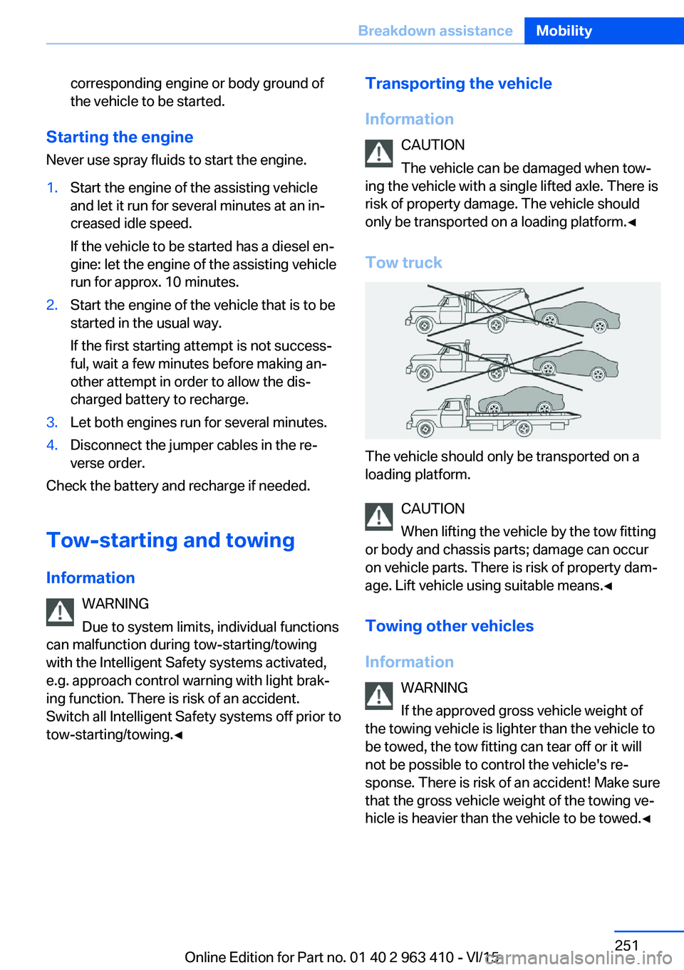
Tow truck
The vehicle should only be transported on a
loading platform.
CAUTION
When lifting the vehicle by the tow fitting
or body and chassis parts; damage can occur
on vehicle parts. There is risk of property dam‐
age. Lift vehicle using suitable means.◀
Towing other vehicles
Information WARNING
If the approved gross vehicle weight of
the towing vehicle is lighter than the vehicle to
be towed, the tow fitting can tear off or it will
not be possible to control the vehicle's re‐
sponse. There is risk of an accident! Make sure
that the gross vehicle weight of the towing ve‐
hicle is heavier than the vehicle to be towed.◀
Seite 251Breakdown assistanceMobility251
Online Edition for Part no. 01 40 2 963 410 - VI/15
Page 252 of 275
CAUTION
If the tow bar or tow rope is attached in‐
correctly, damage to other vehicle parts can
occur. There is risk of property damage. Cor‐
rectly attach the tow bar or tow rope to the tow
fitting.◀▷Switch on the hazard warning system, de‐
pending on local regulations.▷If the electrical system has failed, clearly
identify the vehicle being towed by placing
a sign or a warning triangle in the rear win‐
dow.
Tow bar
The tow fittings used should be on the same
side on both vehicles.
Should it prove impossible to avoid mounting
the tow bar at an offset angle, please observe
the following:
▷Maneuvering capability is limited going
around corners.▷The tow bar will generate lateral forces if it
is secured with an offset.
Tow rope
When starting to tow the vehicle, make sure
that the tow rope is taut.
To avoid jerking and the associated stresses
on the vehicle components when towing, al‐
ways use nylon ropes or nylon straps.
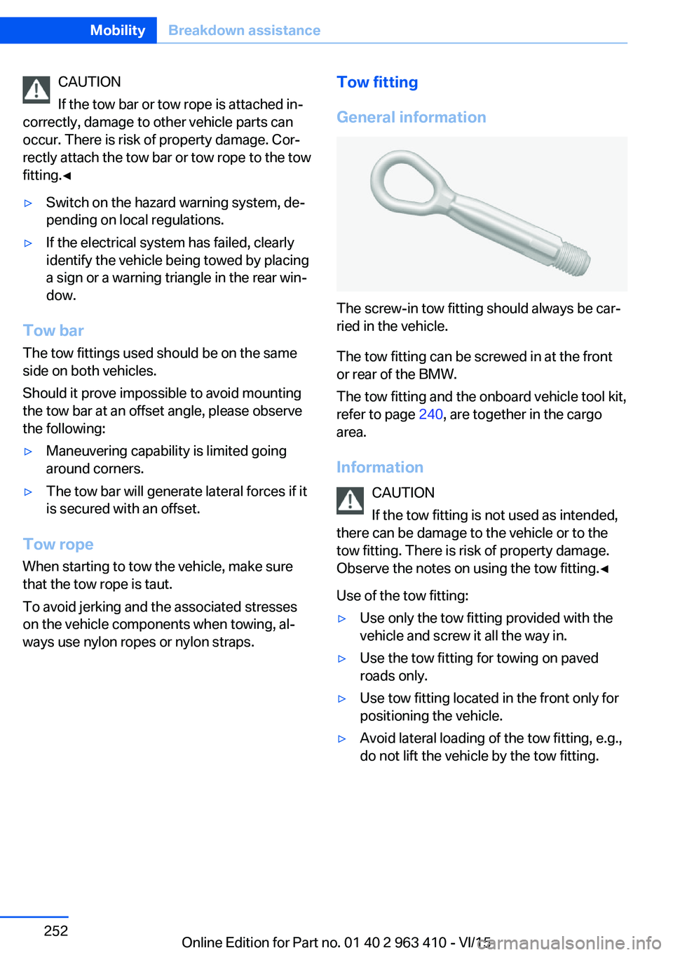
Tow fitting
General information
The screw-in tow fitting should always be car‐
ried in the vehicle.
The tow fitting can be screwed in at the front
or rear of the BMW.
The tow fitting and the onboard vehicle tool kit,
refer to page 240, are together in the cargo
area.
Information CAUTION
If the tow fitting is not used as intended,
there can be damage to the vehicle or to the
tow fitting. There is risk of property damage.
Observe the notes on using the tow fitting.◀
Use of the tow fitting:
▷Use only the tow fitting provided with the
vehicle and screw it all the way in.▷Use the tow fitting for towing on paved
roads only.▷Use tow fitting located in the front only for
positioning the vehicle.▷Avoid lateral loading of the tow fitting, e.g.,
do not lift the vehicle by the tow fitting.Seite 252MobilityBreakdown assistance252
Online Edition for Part no. 01 40 2 963 410 - VI/15
Page 253 of 275
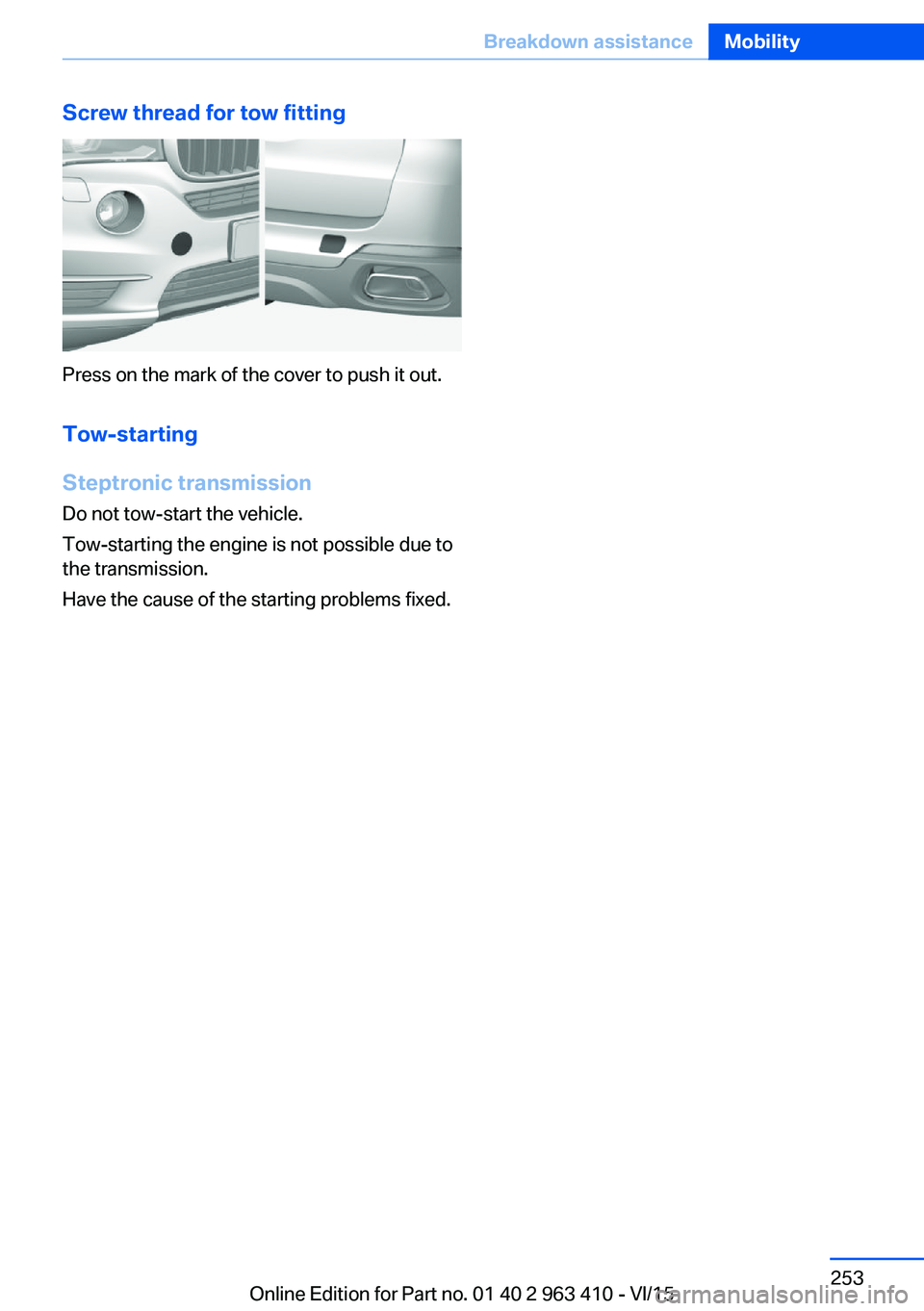
Screw thread for tow fitting
Press on the mark of the cover to push it out.Tow-starting
Steptronic transmission
Do not tow-start the vehicle.
Tow-starting the engine is not possible due to
the transmission.
Have the cause of the starting problems fixed.
Seite 253Breakdown assistanceMobility253
Online Edition for Part no. 01 40 2 963 410 - VI/15