2016 BMW X4 steering wheel
[x] Cancel search: steering wheelPage 140 of 253
InformationWARNING
The use of the system can lead to an in‐
creased risk of accidents in the following situa‐
tions:▷On winding roads.▷In heavy traffic.▷On slippery roads, in fog, snow or rain, or
on a loose road surface.
There is risk of accidents or risk of property
damage. Only use the system if driving at con‐
stant speed is possible.◀
Overview
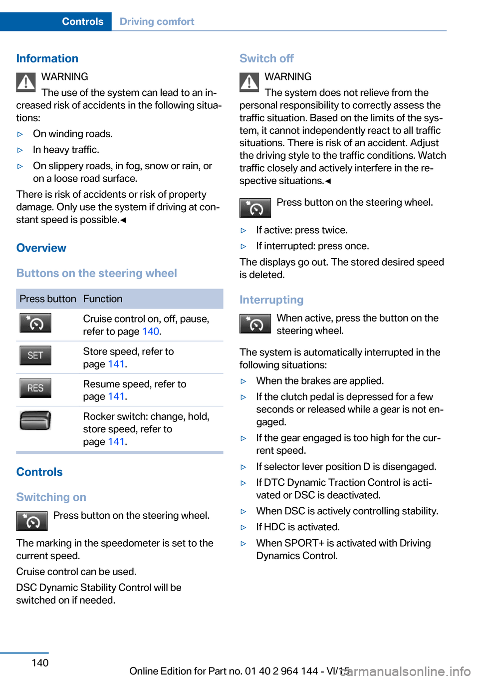
Buttons on the steering wheel
Press buttonFunctionCruise control on, off, pause,
refer to page 140.Store speed, refer to
page 141.Resume speed, refer to
page 141.Rocker switch: change, hold,
store speed, refer to
page 141.
Controls
Switching on Press button on the steering wheel.
The marking in the speedometer is set to the
current speed.
Cruise control can be used.
DSC Dynamic Stability Control will be
switched on if needed.
Switch off
WARNING
The system does not relieve from the
personal responsibility to correctly assess the
traffic situation. Based on the limits of the sys‐
tem, it cannot independently react to all traffic situations. There is risk of an accident. Adjustthe driving style to the traffic conditions. Watch
traffic closely and actively interfere in the re‐
spective situations.◀
Press button on the steering wheel.▷If active: press twice.▷If interrupted: press once.
The displays go out. The stored desired speed
is deleted.
Interrupting When active, press the button on the
steering wheel.
The system is automatically interrupted in the
following situations:
▷When the brakes are applied.▷If the clutch pedal is depressed for a few
seconds or released while a gear is not en‐
gaged.▷If the gear engaged is too high for the cur‐
rent speed.▷If selector lever position D is disengaged.▷If DTC Dynamic Traction Control is acti‐
vated or DSC is deactivated.▷When DSC is actively controlling stability.▷If HDC is activated.▷When SPORT+ is activated with Driving
Dynamics Control.Seite 140ControlsDriving comfort140
Online Edition for Part no. 01 40 2 964 144 - VI/15
Page 141 of 253
Maintaining, storing, and changing the
speed
Information WARNING
The desired speed can be incorrectly ad‐
justed or called up by mistake. There is risk of
an accident. Adjust the desired speed to the
traffic conditions. Watch traffic closely and ac‐
tively interfere in the respective situations.◀
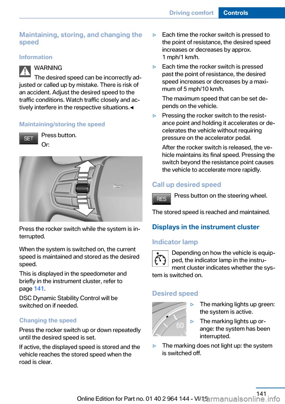
Maintaining/storing the speed Press button.
Or:
Press the rocker switch while the system is in‐
terrupted.
When the system is switched on, the current
speed is maintained and stored as the desired
speed.
This is displayed in the speedometer and
briefly in the instrument cluster, refer to
page 141.
DSC Dynamic Stability Control will be
switched on if needed.
Changing the speed
Press the rocker switch up or down repeatedly
until the desired speed is set.
If active, the displayed speed is stored and the
vehicle reaches the stored speed when the
road is clear.
▷Each time the rocker switch is pressed to
the point of resistance, the desired speed
increases or decreases by approx.
1 mph/1 km/h.▷Each time the rocker switch is pressed
past the point of resistance, the desired
speed increases or decreases by a maxi‐
mum of 5 mph/10 km/h.
The maximum speed that can be set de‐
pends on the vehicle.▷Pressing the rocker switch to the resist‐
ance point and holding it accelerates or de‐
celerates the vehicle without requiring
pressure on the accelerator pedal.
After the rocker switch is released, the ve‐
hicle maintains its final speed. Pressing the
switch beyond the resistance point causes
the vehicle to accelerate more rapidly.
Call up desired speed
Press button on the steering wheel.
The stored speed is reached and maintained. Displays in the instrument cluster
Indicator lamp Depending on how the vehicle is equip‐
ped, the indicator lamp in the instru‐
ment cluster indicates whether the sys‐
tem is switched on.
Desired speed
▷The marking lights up green:
the system is active.▷The marking lights up or‐
ange: the system has been
interrupted.▷The marking does not light up: the system
is switched off.Seite 141Driving comfortControls141
Online Edition for Part no. 01 40 2 964 144 - VI/15
Page 146 of 253

Pathway lines
Pathway lines can be superimposed on the im‐
age of the rearview camera.
Pathway lines help you to estimate the space
required when parking and maneuvering on
level roads.
Pathway lines depend on the current steering
angle and are continuously adjusted to the
steering wheel movements.
Turning circle lines
Turning circle lines can only be superimposed
on the rearview camera image together with
pathway lines.
Turning circle lines show the course of the
smallest possible turning radius on a level
road.
Only one turning radius line is displayed after
the steering wheel is turned past a certain an‐
gle.
Obstacle marking
Obstacles behind the vehicle are detected by
the PDC sensors and, when respectively
equipped, detected by the rearview camera.
Obstacle markings can be faded into the image
of the rearview camera.
Their colored margins of the obstacle mark‐
ings match the markings of the PDC.
Parking using pathway and turning
radius lines
1.Position the vehicle so that the turning ra‐
dius lines lead to within the limits of the
parking space.Seite 146ControlsDriving comfort146
Online Edition for Part no. 01 40 2 964 144 - VI/15
Page 147 of 253
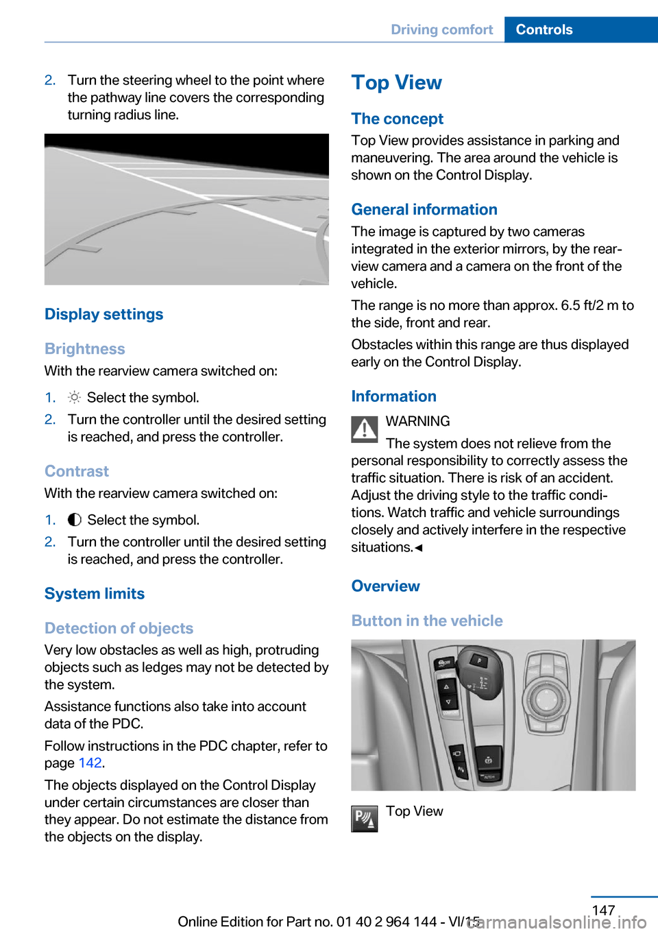
2.Turn the steering wheel to the point where
the pathway line covers the corresponding
turning radius line.
Display settings
Brightness
With the rearview camera switched on:
1. Select the symbol.2.Turn the controller until the desired setting
is reached, and press the controller.
Contrast
With the rearview camera switched on:
1. Select the symbol.2.Turn the controller until the desired setting
is reached, and press the controller.
System limits
Detection of objects
Very low obstacles as well as high, protruding
objects such as ledges may not be detected by
the system.
Assistance functions also take into account
data of the PDC.
Follow instructions in the PDC chapter, refer to
page 142.
The objects displayed on the Control Display
under certain circumstances are closer than
they appear. Do not estimate the distance from
the objects on the display.
Top View
The concept Top View provides assistance in parking and
maneuvering. The area around the vehicle is
shown on the Control Display.
General information The image is captured by two cameras
integrated in the exterior mirrors, by the rear‐
view camera and a camera on the front of the
vehicle.
The range is no more than approx. 6.5 ft/2 m to
the side, front and rear.
Obstacles within this range are thus displayed
early on the Control Display.
Information WARNING
The system does not relieve from the
personal responsibility to correctly assess the
traffic situation. There is risk of an accident.
Adjust the driving style to the traffic condi‐ tions. Watch traffic and vehicle surroundings
closely and actively interfere in the respective
situations.◀
Overview
Button in the vehicle
Top View
Seite 147Driving comfortControls147
Online Edition for Part no. 01 40 2 964 144 - VI/15
Page 149 of 253
2.Turn the controller until the desired setting
is reached, and press the controller.
Displaying the turning radius and
pathway lines
▷The static, red turning radius line shows
the space needed to the side of the vehicle
when the steering wheel is turned all the
way.▷The variable, green pathway line assists
you in assessing the amount of space ac‐
tually needed to the side of the vehicle.
The lane line depends on the engaged
gear and the current steering angle. The
track line is continuously adjusted for the
steering wheel movement.
"Parking aid lines"
Turning circle and pathway lines are displayed.
System limits
A Check Control message is displayed when a
camera is not working.
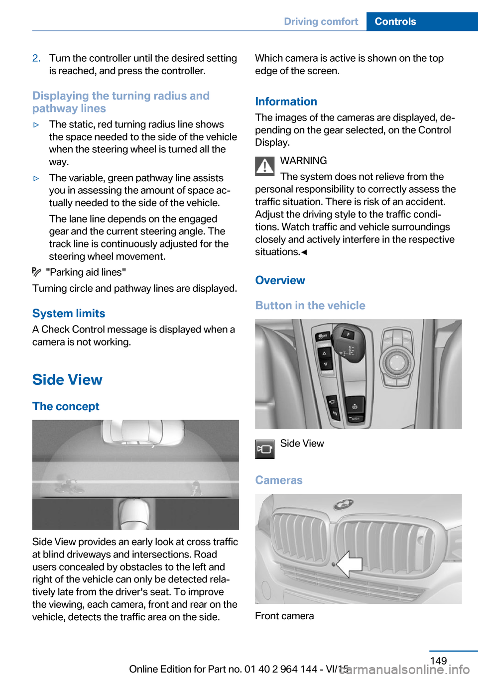
Side View The concept
Side View provides an early look at cross traffic
at blind driveways and intersections. Road
users concealed by obstacles to the left and
right of the vehicle can only be detected rela‐
tively late from the driver's seat. To improve
the viewing, each camera, front and rear on the
vehicle, detects the traffic area on the side.
Which camera is active is shown on the top
edge of the screen.
Information The images of the cameras are displayed, de‐
pending on the gear selected, on the Control
Display.
WARNING
The system does not relieve from the
personal responsibility to correctly assess the
traffic situation. There is risk of an accident.
Adjust the driving style to the traffic condi‐
tions. Watch traffic and vehicle surroundings
closely and actively interfere in the respective
situations.◀
Overview
Button in the vehicle
Side View
Cameras
Front camera
Seite 149Driving comfortControls149
Online Edition for Part no. 01 40 2 964 144 - VI/15
Page 153 of 253
Parking using the parking assistantWARNING
The system does not relieve from the
personal responsibility to correctly assess the
traffic situation. There is risk of an accident.
Adjust the driving style to the traffic condi‐
tions. Watch traffic and vehicle surroundings
closely and actively interfere in the respective
situations.◀1.Switch on the parking assistant and acti‐
vate it if needed.
The status of the parking space search is
indicated on the Control Display.2.Follow the instructions on the Control Dis‐
play.
The best possible parking position will
come after gear change on the stationary
vehicle - wait for the automatic steering
wheel move.
The end of the parking procedure is indi‐
cated on the Control Display.3.Adjust the parking position yourself if
needed.
Interrupting manually
The parking assistant can be interrupted at any
time:
▷ "Parking Assistant" Select the symbol
on the Control Display.▷Press button.
Interrupting automatically
The system is interrupted automatically in the
following situations:
▷If the driver grasps the steering wheel or if
he takes over steering.▷If a gear is selected that does not match
the instruction on the Control Display.▷If the vehicle speed exceeds approx.
6 mph/10 km/h.▷Possible on snow-covered or slippery road
surfaces.▷When there are obstacles that are hard to
overcome, such as curbs.▷When there are obstacles that suddenly
arise.▷If the Park Distance Control PDC displays
clearances that are too small.▷If a maximum number of parking attempts
or the time taken for parking is exceeded.▷When switching to another function on the
Control Display.
A Check Control message is displayed.
Resume An interrupted parking procedure can be con‐
tinued if needed.
Follow the instructions on the Control Display
to do this.
System limits
No parking assistance
The parking assistant does not offer assis‐
tance in the following situations:
▷In tight curves.
Functional limitations
The system may not be fully functional in the
following situations:
▷On bumpy road surfaces such as gravel
roads.▷On slippery ground.▷On steep uphill or downhill grades.▷With accumulations of leaves/snow in the
parking space.
Limits of ultrasonic measurement
Ultrasonic measuring might not function under
the following circumstances:
▷For small children and animals.Seite 153Driving comfortControls153
Online Edition for Part no. 01 40 2 964 144 - VI/15
Page 196 of 253

Wheels and tiresVehicle features and options
This chapter describes all standard, country-
specific and optional features offered with the
series. It also describes features that are not
necessarily available in your car, e. g., due to
the selected options or country versions. This
also applies to safety-related functions and
systems. The respectively applicable country
provisions must be observed when using the
respective features and systems.
Tire inflation pressure Safety information
The tire characteristics and tire inflation pres‐
sure influence the following:▷The service life of the tires.▷Road safety.▷Driving comfort.
Checking the tire inflation pressure
WARNING
A tire with low or missing tire inflation
pressure impacts handling, such as steering
and braking response. There is risk of an acci‐
dent. Regularly check the tire inflation pres‐
sure, and correct it as needed, e.g. twice a
month and before a long trip.◀
Tires have a natural, consistent loss of tire in‐
flation pressure.
Tires heat up while driving, and the tire infla‐
tion pressure increases along with the tire's
temperature. The tire inflation pressure speci‐
fications relate to cold tires or tires with the
ambient temperature.
Only check the tire inflation pressure when the
tires are cold. This means after driving no more
than 1.25 miles/2 km or when the vehicle has
been parked for at least 2 hours.
The displays of inflation devices may under-
read by up to 0.1 bar, 2 psi.
For Flat Tire Monitor: after correcting the tire
inflation pressure, reinitialize the Flat Tire
Monitor.
For Tire Pressure Monitor: after correcting the
tire inflation pressure, reset the Tire Pressure
Monitor.
Tire inflation pressure specifications
The tire inflation pressure table, refer to
page 197, contains all tire inflation pressure
specifications for the specified tire sizes at the
ambient temperature. The tire inflation pres‐
sure values apply to tire sizes approved by the
manufacturer of the vehicle for the vehicle
type.
To identify the correct tire inflation pressure,
please note the following:▷Tire sizes of your vehicle.▷Maximum permitted driving speed.
Tire inflation pressures up to
100 mph/160 km/h
For speeds of up to 100 mph/160 km/h and for
optimum driving comfort, note the pressure
values in the tire inflation pressure table, refer
to page 197, and adjust as necessary.
Seite 196MobilityWheels and tires196
Online Edition for Part no. 01 40 2 964 144 - VI/15
Page 203 of 253
Changing run-flat tires
For your own safety, only use run-flat tires. No
spare tire is available in the case of a flat tire. A
dealer’s service center or another qualified
service center or repair shop will be glad to an‐
swer additional questions at any time.
Mobility System The conceptWith the Mobility System, minor tire damage
can be sealed quickly to enable continued
travel. To accomplish this, sealant is pumped
into the tires, which seals the damage from the
inside.
The compressor can be used to check the tire
inflation pressure.
Information▷Follow the instructions on using the Mobi‐
lity System found on the compressor and
sealant container.▷Use of the Mobility System may be ineffec‐
tive if the tire puncture measures approx.
1/8 in/4 mm or more.▷Contact a dealer’s service center or an‐
other qualified service center or repair
shop if the tire cannot be made drivable.▷If possible, do not remove foreign bodies
that have penetrated the tire.▷Pull the speed limit sticker off the sealant
container and apply it to the steering
wheel.▷The use of a sealant can damage the TPM
wheel electronics. In this case, have the
electronics checked at the next opportu‐
nity and have them replaced if needed.
DANGER
If the exhaust pipe is blocked or ventila‐
tion is insufficient, harmful exhaust gases can
enter into the vehicle. The exhaust gases con‐
tain carbon monoxide, an odorless and color‐
less but highly toxic gas. In enclosed areas, ex‐
haust gases can also accumulate outside of
the vehicle. There is danger to life. Keep the
exhaust pipe free and ensure sufficient ventila‐
tion.◀
Storage
The Mobility System is located under the cargo floor panel.
Sealant container▷Sealant container, arrow 1.▷Filling hose, arrow 2.
Observe use-by date on the sealant container.
Compressor
1Holder for bottle2Compressor3Connector/cable for socket4Connection hose5On/off switch6Inflation pressure dial7Reduce inflation pressureSeite 203Wheels and tiresMobility203
Online Edition for Part no. 01 40 2 964 144 - VI/15