2016 BMW X4 turn signal
[x] Cancel search: turn signalPage 117 of 253

Radar sensor
The radar sensor is located in the lower area of
the front bumper.
Always keep radar sensor clean and unob‐
structed.
Camera
The camera is installed near the interior rear‐
view mirror.
Keep the windshield in the area behind the in‐
terior rearview mirror clean and clear.
Switching on/off
Switching on automatically The system is automatically active after every
driving-off.
Switching on/off manually Press button briefly:
▷The menu for the intelligent safety
system is displayed. The systems
are individually switched off ac‐cording to their respective set‐
tings.▷LED lights up orange or goes out respec‐
tive to their individual settings.
Adjust as needed. Individual settings are
stored for the profile currently used.
Press button again:
▷All Intelligent Safety systems are
activated.▷The LED lights up green.
Hold down button:
▷All Intelligent Safety systems are
turned off.▷The LED goes out.
Setting the warning time
The warning time can be set via iDrive.
1."Settings"2."Frontal Coll. Warning"3.Activate the desired time on the Control
Display.
The selected time is stored for the profile cur‐
rently used.
Warning with braking function
Display If a collision with a recognized vehicle is immi‐
nent a warning symbol appears in the instru‐
ment cluster and in the Head-Up Display.
SymbolMeasureSymbol lights up red: prewarning.
Brake and increase distance.Symbol flashes red and an acoustic
signal sounds: acute warning.
You are requested to intervene by
braking or make an evasive maneu‐
ver.Seite 117SafetyControls117
Online Edition for Part no. 01 40 2 964 144 - VI/15
Page 121 of 253
▷Pedestrians that are not detected as such
because of the viewing angle or contour.▷Pedestrians outside of the detection range.▷Pedestrians having a body size less than
32 in/80 cm.
Functional limitations
The system may not be fully functional or may
not be available in the following situations:
The system may not be fully functional in the
following situations:
▷In heavy fog, rain, sprayed water or snow‐
fall.▷In tight curves.▷If the driving stability control systems are
deactivated, e.g. DSC OFF.▷If the field of view of the camera or the front
windshield are dirty or covered.▷Up to 10 seconds after the start of the en‐
gine, via the Start/Stop button.▷During calibration of the camera immedi‐
ately after vehicle delivery.▷If there are constant blinding effects be‐
cause of oncoming light, e. g., from the sun
low in the sky.▷When it is dark outside.
Lane departure warning
The concept Starting at a specific speed, this system alerts
you when the vehicle on streets with lane
markings is about to leave the lane. This
speed, depending on the country version, is
between 35 mph/55 km/h and
45 mph/70 km/h.
The steering wheel begins vibrating gently in
the event of warnings. The time of the warning
may vary depending on the current driving sit‐
uation.
The system does not provide a warning if the
turn signal is set before leaving the lane.
Information WARNING
The system does not relieve from the
personal responsibility to correctly assess
route and traffic situation. There is risk of an
accident. Adjust the driving style to the traffic
conditions. Watch traffic closely and actively interfere in the respective situations. In the
event of a warning, do not unnecessarily jerk
the steering wheel.◀
Overview
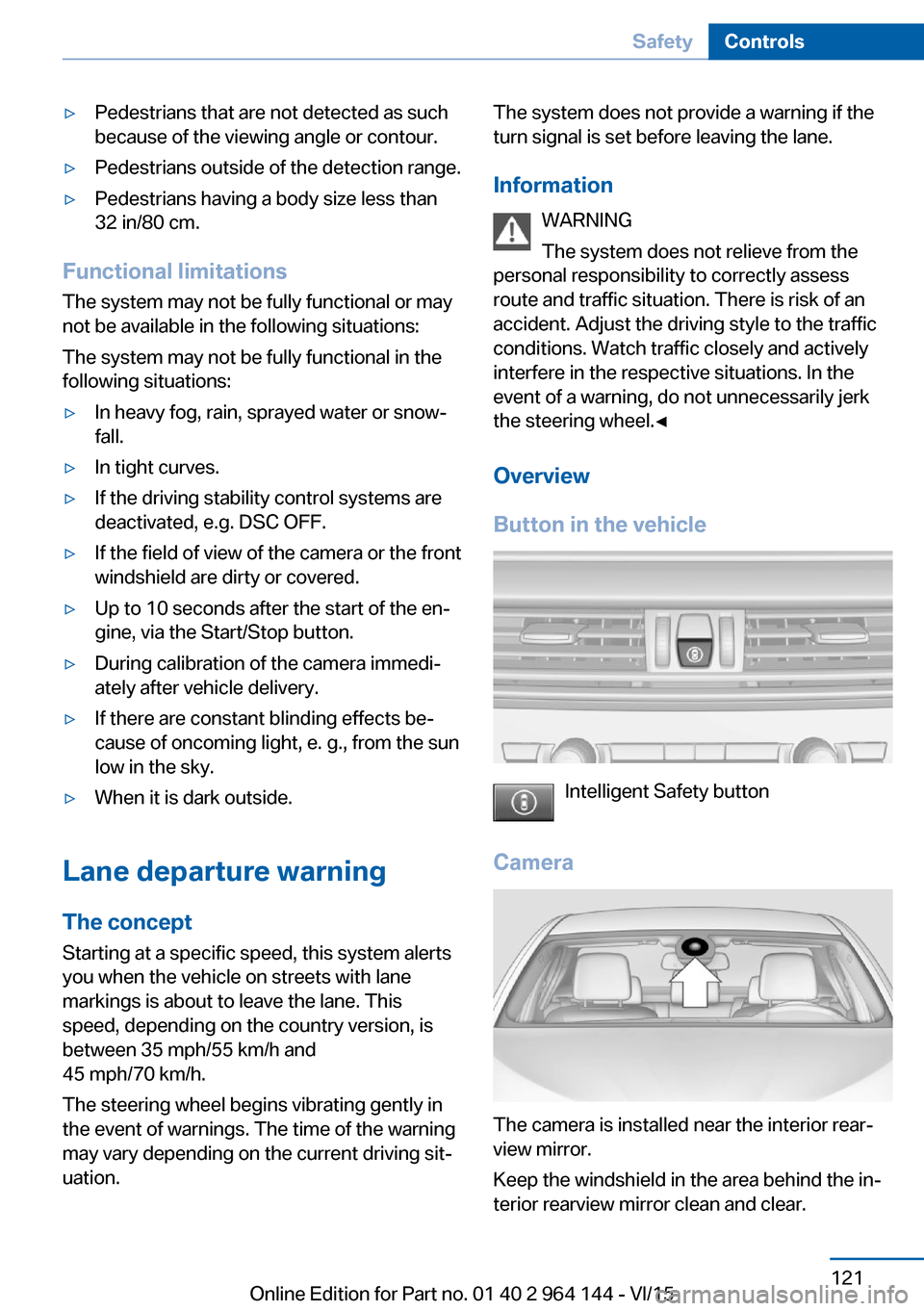
Button in the vehicle
Intelligent Safety button
Camera
The camera is installed near the interior rear‐
view mirror.
Keep the windshield in the area behind the in‐
terior rearview mirror clean and clear.
Seite 121SafetyControls121
Online Edition for Part no. 01 40 2 964 144 - VI/15
Page 122 of 253
Switching on/off
Switching on automatically The lane departure warning is automatically
activated after departure, if the function was
switched on the last time the engine was stop‐
ped.
Switching on/off manually Press button briefly:▷The menu for the intelligent safety
system is displayed. The systems
are individually switched off ac‐
cording to their respective set‐
tings.▷LED lights up orange or goes out respec‐
tive to their individual settings.
Adjust as needed. Individual settings are
stored for the profile currently used.
Press button again:
▷All Intelligent Safety systems are
activated.▷The LED lights up green.
Hold down button:
▷All Intelligent Safety systems are
turned off.▷The LED goes out.
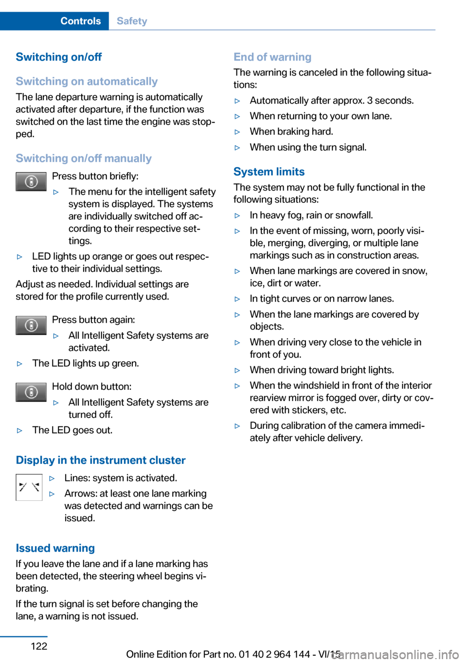
Display in the instrument cluster
▷Lines: system is activated.▷Arrows: at least one lane marking
was detected and warnings can be
issued.
Issued warning
If you leave the lane and if a lane marking has
been detected, the steering wheel begins vi‐
brating.
If the turn signal is set before changing the
lane, a warning is not issued.
End of warning
The warning is canceled in the following situa‐
tions:▷Automatically after approx. 3 seconds.▷When returning to your own lane.▷When braking hard.▷When using the turn signal.
System limits
The system may not be fully functional in the
following situations:
▷In heavy fog, rain or snowfall.▷In the event of missing, worn, poorly visi‐
ble, merging, diverging, or multiple lane
markings such as in construction areas.▷When lane markings are covered in snow,
ice, dirt or water.▷In tight curves or on narrow lanes.▷When the lane markings are covered by
objects.▷When driving very close to the vehicle in
front of you.▷When driving toward bright lights.▷When the windshield in front of the interior
rearview mirror is fogged over, dirty or cov‐
ered with stickers, etc.▷During calibration of the camera immedi‐
ately after vehicle delivery.Seite 122ControlsSafety122
Online Edition for Part no. 01 40 2 964 144 - VI/15
Page 123 of 253
Active Blind Spot Detection
The concept
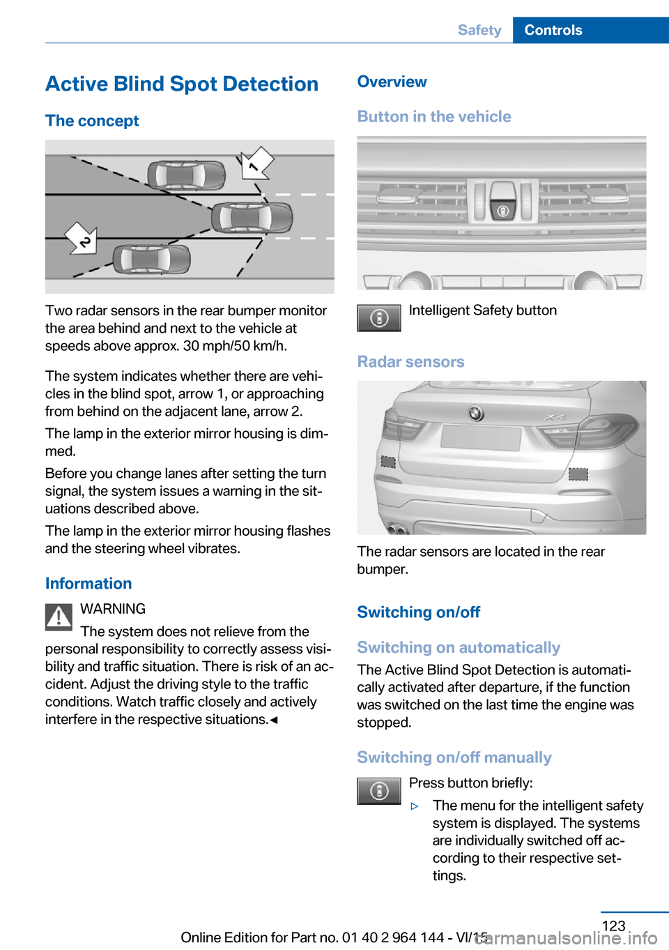
Two radar sensors in the rear bumper monitor
the area behind and next to the vehicle at
speeds above approx. 30 mph/50 km/h.
The system indicates whether there are vehi‐
cles in the blind spot, arrow 1, or approaching
from behind on the adjacent lane, arrow 2.
The lamp in the exterior mirror housing is dim‐
med.
Before you change lanes after setting the turn
signal, the system issues a warning in the sit‐
uations described above.
The lamp in the exterior mirror housing flashes
and the steering wheel vibrates.
Information WARNING
The system does not relieve from the
personal responsibility to correctly assess visi‐
bility and traffic situation. There is risk of an ac‐
cident. Adjust the driving style to the traffic
conditions. Watch traffic closely and actively interfere in the respective situations.◀
Overview
Button in the vehicle
Intelligent Safety button
Radar sensors
The radar sensors are located in the rear
bumper.
Switching on/off
Switching on automatically The Active Blind Spot Detection is automati‐
cally activated after departure, if the function
was switched on the last time the engine was
stopped.
Switching on/off manually Press button briefly:
▷The menu for the intelligent safety
system is displayed. The systems
are individually switched off ac‐
cording to their respective set‐
tings.Seite 123SafetyControls123
Online Edition for Part no. 01 40 2 964 144 - VI/15
Page 124 of 253
▷LED lights up orange or goes out respec‐
tive to their individual settings.
Adjust as needed. Individual settings are
stored for the profile currently used.
Press button again:
▷All Intelligent Safety systems are
activated.▷The LED lights up green.
Hold down button:
▷All Intelligent Safety systems are
turned off.▷The LED goes out.
Display
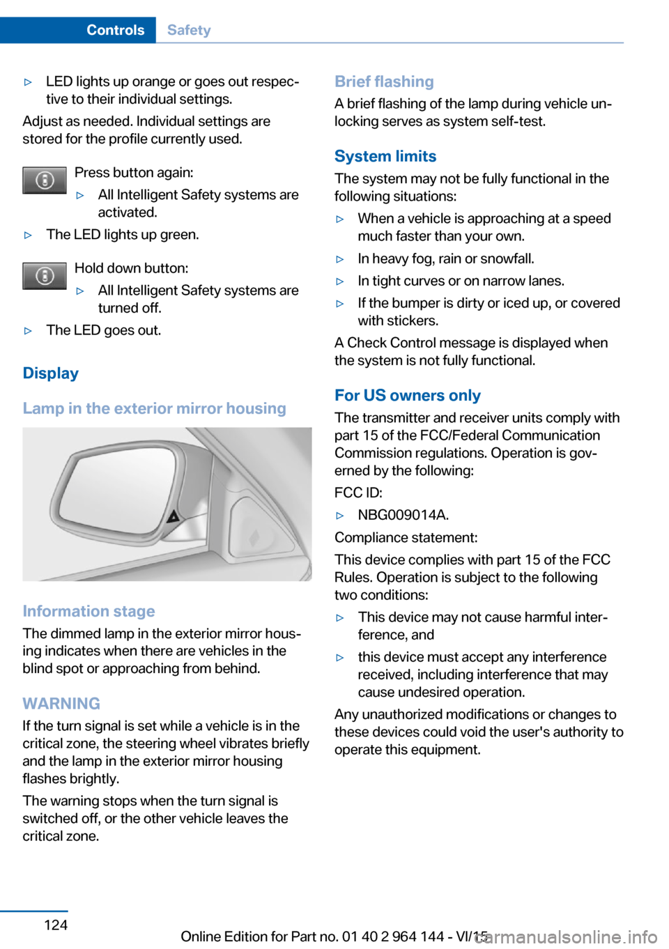
Lamp in the exterior mirror housing
Information stage
The dimmed lamp in the exterior mirror hous‐
ing indicates when there are vehicles in the
blind spot or approaching from behind.
WARNING If the turn signal is set while a vehicle is in the
critical zone, the steering wheel vibrates briefly
and the lamp in the exterior mirror housing
flashes brightly.
The warning stops when the turn signal is
switched off, or the other vehicle leaves the
critical zone.
Brief flashing
A brief flashing of the lamp during vehicle un‐
locking serves as system self-test.
System limits
The system may not be fully functional in the
following situations:▷When a vehicle is approaching at a speed
much faster than your own.▷In heavy fog, rain or snowfall.▷In tight curves or on narrow lanes.▷If the bumper is dirty or iced up, or covered
with stickers.
A Check Control message is displayed when
the system is not fully functional.
For US owners only The transmitter and receiver units comply with
part 15 of the FCC/Federal Communication
Commission regulations. Operation is gov‐
erned by the following:
FCC ID:
▷NBG009014A.
Compliance statement:
This device complies with part 15 of the FCC
Rules. Operation is subject to the following
two conditions:
▷This device may not cause harmful inter‐
ference, and▷this device must accept any interference
received, including interference that may
cause undesired operation.
Any unauthorized modifications or changes to
these devices could void the user's authority to
operate this equipment.
Seite 124ControlsSafety124
Online Edition for Part no. 01 40 2 964 144 - VI/15
Page 143 of 253

Switching on/off
Switching on automatically PDC switches on automatically in the following
situations:▷If selector lever position R is engaged
when the engine is running.
The rearview camera also switches on.▷If equipped with front PDC: when obsta‐
cles are detected behind or in front of the
vehicle by PDC and the speed is slower
than approx. 2.5 mph/4 km/h.
You may turn off automatic activation:
1."Settings"2."Parking"3.Select setting.
Settings are stored for the profile currently
used.
Automatic deactivation during forward
travel
The system switches off when a certain driving
distance or speed is exceeded.
Switch the system back on if needed.
With front PDC: switching on/off
manually
Press button.
▷On: the LED lights up.▷Off: the LED goes out.
The rearview camera image is displayed when
the reverse gear is engaged by pressing the
button.
Display
Signal tones When approaching an object, an intermittent
sound indicates the position of the object. E. g.
if an object is detected to the left rear of the
vehicle, a signal tone sounds from the left rear
speaker.
The shorter the distance to the object, the
shorter the intervals.
If the distance to a detected object is less than
approx. 10 in/25 cm, a continuous tone is
sounded.
With front PDC: if objects are located both in
front of and behind the vehicle, an alternating
continuous signal is sounded.
The signal tone is switched off, when selector
lever position P is engaged on vehicles with
Steptronic transmission.
Volume
The ratio of the PDC signal tone volume to the
entertainment volume can be adjusted.1."Multimedia", "Radio" or "Settings"2."Tone"3."Volume settings"4."PDC"5.Turn the controller until the desired setting
is selected.6.Press the controller.
Settings are stored for the profile currently
used.
Visual warning
The approach of the vehicle to an object can
be shown on the Control Display. Objects that
are farther away are already displayed on the
Control Display before a signal sounds.
A display appears as soon as Park Distance
Control (PDC) is activated.
The range of the sensors is represented in the
colors green, yellow and red.
When the image of the rearview camera is dis‐
played, the switch can be made to PDC:
"Rear view camera"
Seite 143Driving comfortControls143
Online Edition for Part no. 01 40 2 964 144 - VI/15
Page 152 of 253
▷Maximum distance to row of parked vehi‐
cles: 5 ft/1.5 m.
Suitable parking space
▷Gaps behind an object that has a min.
length of 5 ft/1.5 m.▷Gap between two objects with a minimum
length of approx. 5 ft/1.5 m.▷Min. length of gap between two objects:
your vehicle's length plus approx.
3.3 ft/1.0 m.▷Minimum depth: approx. 5 ft/1.5 m.
Regarding the parking procedure
▷Doors and tailgate closed.▷Parking brake released.▷When parking in parking spaces on the
driver's side, the corresponding turn signal
must be set where applicable.
Switching on/off
Switching on with the button Press button.
The LED lights up.
The current status of the parking space search
is indicated on the Control Display.
Parking assistant is activated automatically.
Switching on with the reverse gear
Shift into reverse.
The current status of the parking space search
is indicated on the Control Display.
To activate:
"Parking Assistant"
Switch off
The system can be deactivated as follows:
▷Press button.▷Switch off the ignition.Display on the Control Display
System activated/deactivatedSymbolMeaning Gray: the system is not available.
White: the system is available but
not activated. The system is activated.
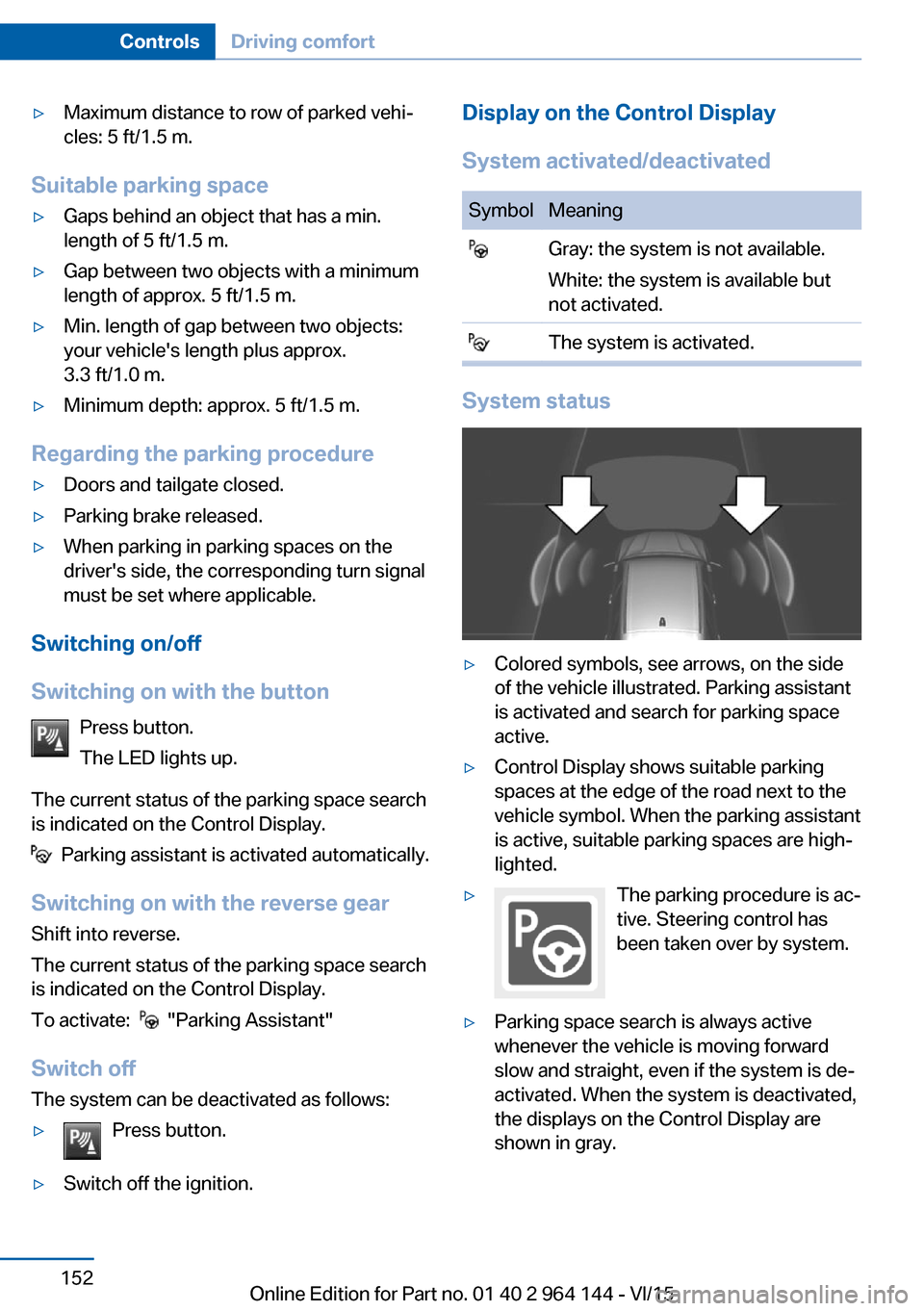
System status
▷Colored symbols, see arrows, on the side
of the vehicle illustrated. Parking assistant
is activated and search for parking space
active.▷Control Display shows suitable parking
spaces at the edge of the road next to the
vehicle symbol. When the parking assistant
is active, suitable parking spaces are high‐
lighted.▷The parking procedure is ac‐
tive. Steering control has
been taken over by system.▷Parking space search is always active
whenever the vehicle is moving forward
slow and straight, even if the system is de‐
activated. When the system is deactivated,
the displays on the Control Display are
shown in gray.Seite 152ControlsDriving comfort152
Online Edition for Part no. 01 40 2 964 144 - VI/15
Page 219 of 253

3Turn signal/side marker light4Parking lights5Daytime running lights
Accessing the low beams and parking
lights
Follow general instructions, refer to page 217.
1.Open the hood, refer to page 207.2.Turn the cover counterclockwise and re‐
move.3.The upper bulb is the low beam and the
lower bulb is the parking lamp.
Low beams
55-watt bulb, H7.
1.Tip the connector with the bulb down
slightly and pull out carefully.2.Pull the bulb off the connector and insert
the new bulb.3.Install the new bulb in reverse order of re‐
moval.4.Place the cover according to the arrow
markings on the headlight housing.5.Close the headlight housing with the lid.
Parking lights
5-watt bulb, W5W.
1.Remove the bulb holder.2.Carefully remove the bulb from the socket.3.Install the new bulb in reverse order of re‐
moval.4.Place the cover according to the arrow
markings on the headlight housing.5.Close the headlight housing with the lid.
Accessing the high beams/headlight
flasher and daytime running lights
Follow general instructions, refer to page 217.
1.Open the hood, refer to page 207.2.Turn the cover counterclockwise and re‐
move.3.The upper bulb is the high beam/headlight
flasher and the lower bulb is the daytime
running lights.
High beams/headlight flasher
55-watt bulb, H7.
1.Tip the connector with the bulb up slightly
and pull out carefully.2.Pull the bulb off the connector and insert
the new bulb.3.Install the new bulb in reverse order of re‐
moval.4.Place the cover according to the arrow
markings on the headlight housing.5.Close the headlight housing with the lid.
Daytime running lights
21-watt bulb, W21W.
1.Turn the bulb holder counterclockwise and
remove.2.Carefully remove the bulb from the socket.Seite 219Replacing componentsMobility219
Online Edition for Part no. 01 40 2 964 144 - VI/15