2016 BMW X4 light
[x] Cancel search: lightPage 219 of 253

3Turn signal/side marker light4Parking lights5Daytime running lights
Accessing the low beams and parking
lights
Follow general instructions, refer to page 217.
1.Open the hood, refer to page 207.2.Turn the cover counterclockwise and re‐
move.3.The upper bulb is the low beam and the
lower bulb is the parking lamp.
Low beams
55-watt bulb, H7.
1.Tip the connector with the bulb down
slightly and pull out carefully.2.Pull the bulb off the connector and insert
the new bulb.3.Install the new bulb in reverse order of re‐
moval.4.Place the cover according to the arrow
markings on the headlight housing.5.Close the headlight housing with the lid.
Parking lights
5-watt bulb, W5W.
1.Remove the bulb holder.2.Carefully remove the bulb from the socket.3.Install the new bulb in reverse order of re‐
moval.4.Place the cover according to the arrow
markings on the headlight housing.5.Close the headlight housing with the lid.
Accessing the high beams/headlight
flasher and daytime running lights
Follow general instructions, refer to page 217.
1.Open the hood, refer to page 207.2.Turn the cover counterclockwise and re‐
move.3.The upper bulb is the high beam/headlight
flasher and the lower bulb is the daytime
running lights.
High beams/headlight flasher
55-watt bulb, H7.
1.Tip the connector with the bulb up slightly
and pull out carefully.2.Pull the bulb off the connector and insert
the new bulb.3.Install the new bulb in reverse order of re‐
moval.4.Place the cover according to the arrow
markings on the headlight housing.5.Close the headlight housing with the lid.
Daytime running lights
21-watt bulb, W21W.
1.Turn the bulb holder counterclockwise and
remove.2.Carefully remove the bulb from the socket.Seite 219Replacing componentsMobility219
Online Edition for Part no. 01 40 2 964 144 - VI/15
Page 220 of 253

3.Install the new bulb in reverse order of re‐
moval.4.Place the cover according to the arrow
markings on the headlight housing.5.Close the headlight housing with the lid.
Xenon headlights
Information
Because of the long service life of these bulbs,
the likelihood of failure is very low. Switching
the lights on and off frequently shortens their
service life.
If a bulb fails, turn on the front fog lights and
continue the trip with great care. Comply with
local regulations.
DANGER
There can be high voltage in the lighting
system. There is danger to life. The manufac‐
turer of your vehicle recommends that the
work on the lighting system including bulb re‐
placement be performed by a dealer’s service
center or another qualified service center or re‐
pair shop.◀
For checking and adjusting headlamp aim,
contact a dealer’s service center or another
qualified service center or repair shop.
Overview
1Parking lights / daytime running lights2Low beams/high beams/headlight flasher3Turn signal/side marker lightXenon headlights
Low beams and high beams are designed with
xenon technology.
The parking lights and daylight running lights
are made using LED technology.
Contact a dealer’s service center or another
qualified service center or repair shop in the
event of a malfunction.
LED headlights Light-emitting diodes (LEDs)
With LED headlights, all front lights and side
indicators are designed with LED technology.
If an LED fails, switch on the front fog lamps
and continue the trip with great care. Comply with local regulations.
Contact a dealer’s service center or another
qualified service center or repair shop in the
event of a malfunction.
Front fog lights
Follow general instructions, refer to page 217.
35-watt bulb, H8.1.Insert the screwdriver from the onboard
vehicle tool kit, with the flat side on the clip,
arrow 1.2.Turn the screwdriver by 90°, arrow 2.3.Remove the front fog lamp toward the
front.Seite 220MobilityReplacing components220
Online Edition for Part no. 01 40 2 964 144 - VI/15
Page 221 of 253

4.Detach the connector.5.Turn the bulb bracket and remove it.6.Remove the bulb and replace it.7.Proceed in reverse order to insert the front
fog lamp. Note the guide rails in doing so.
LED front fog lights
These front fog lights are made using LED
technology. Contact a dealer’s service center
or another qualified service center or repair
shop in the event of a malfunction.
Turn signal
Information
Follow general instructions, refer to page 217.
The turn signals are located next to each low
beam in the engine compartment.
21-watt bulb, PY 21W.
Replacement1.Open the hood, refer to page 207.2.Turn the bulb with the socket counter‐
clockwise and carefully remove.3.Push the bulb down slightly and unscrew
from the socket.4.To insert the new bulb, proceed in reverse
order of removal.
Turn signal in exterior mirror
The turn signals in the exterior mirrors feature
LED technology. Contact a dealer’s service
center or another qualified service center or re‐
pair shop in the event of a malfunction.
Tail lights, bulb replacement
Overview
1Turn signal2Backup lamp3Inside brake lamp4Rear lamp5Brake lightSeite 221Replacing componentsMobility221
Online Edition for Part no. 01 40 2 964 144 - VI/15
Page 222 of 253

Bulb replacement, exterior tail lightsGeneral information
Follow general instructions, refer to page 217.
Turn signal: 21-watt bulb, P21W.
Outer brake lamp: 24-watt bulb, PW24W.
The rear lamp features LED technology. Con‐
tact a dealer’s service center or another quali‐
fied service center or repair shop in the event
of a malfunction.
Removing the exterior tail lamp1.Open the tailgate.2.Insert the screwdriver from the onboard
vehicle tool kit, refer to page 217, front‐
ward at an angle into the cover opening, ar‐
row 1.3.Pry the cover out of the lower plug connec‐
tor, arrow 2.▷Left vehicle side: pry to the right.▷Right vehicle side: pry to the left.4.To unfasten the upper plug connector, ar‐
row 3, carefully remove the cover, arrow 4.5.Loosen the two nuts with the screwdriver
handle, arrows.6.Remove the tail lamp from the body and
detach the connector from the bulb holder.
Replacing the bulbs
1.Loosen the three fasteners, arrows 1, on
the bulb holder and remove the bulb holder
from the tail lamp, arrow 2.2.Press the nonworking bulb gently into the
socket, turn counterclockwise and remove.
The turn signal is the upper bulb and the
brake lamp is the lower bulb on the bulb
holder.3.Proceed in the reverse order to insert the
new bulb and attach the bulb holder. Make
sure that the bulb holder engages in all fas‐
teners.
Installing the tail lamp
1.Attach the connector to the tail lamp.Seite 222MobilityReplacing components222
Online Edition for Part no. 01 40 2 964 144 - VI/15
Page 223 of 253

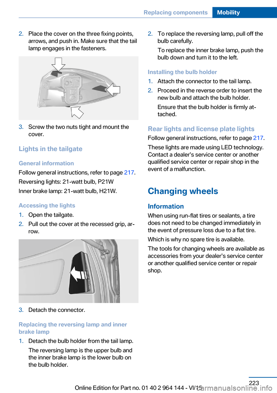
2.Place the cover on the three fixing points,
arrows, and push in. Make sure that the tail
lamp engages in the fasteners.3.Screw the two nuts tight and mount the
cover.
Lights in the tailgate
General information
Follow general instructions, refer to page 217.
Reversing lights: 21-watt bulb, P21W
Inner brake lamp: 21-watt bulb, H21W.
Accessing the lights
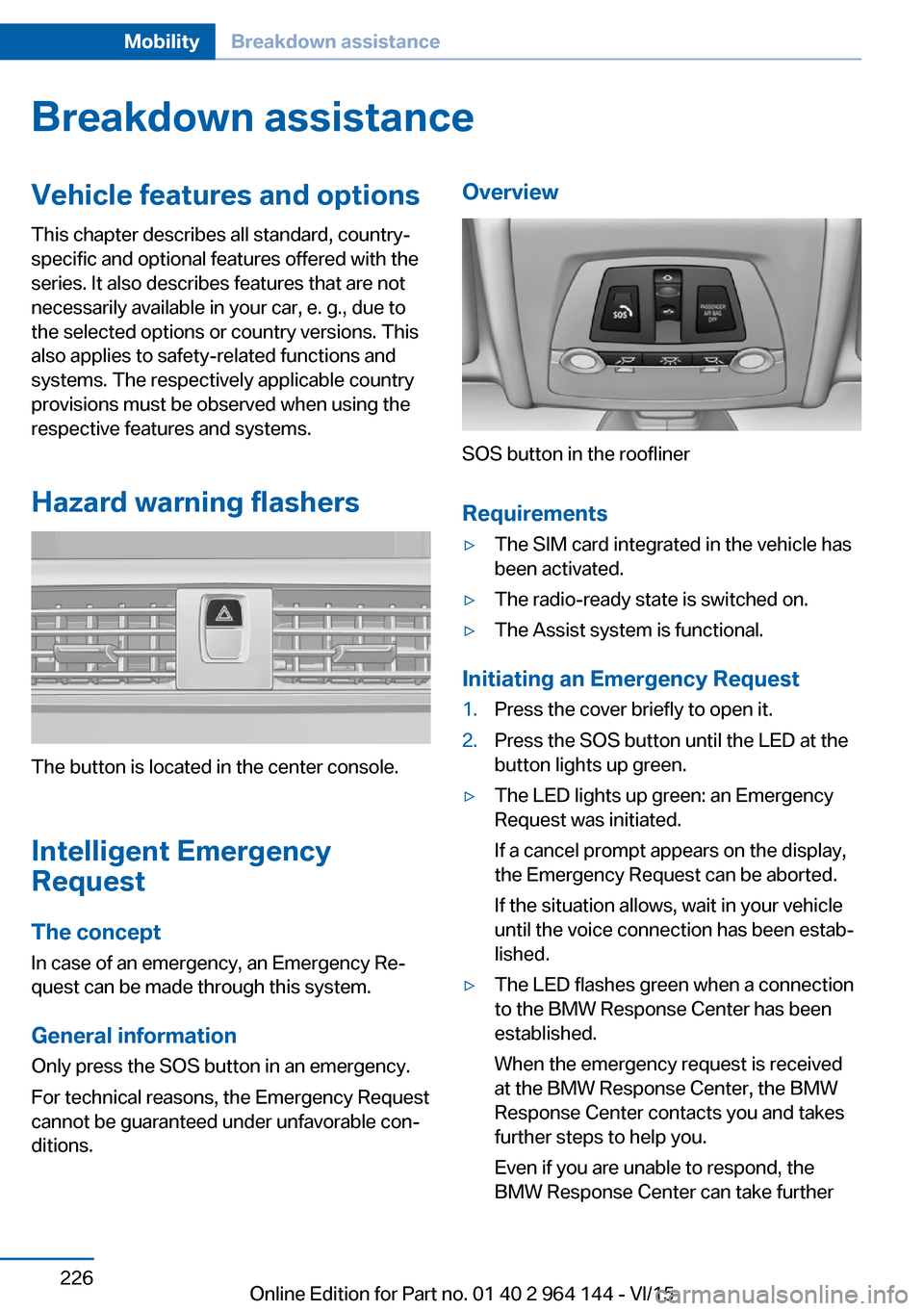
1.Open the tailgate.2.Pull out the cover at the recessed grip, ar‐
row.3.Detach the connector.
Replacing the reversing lamp and inner
brake lamp
1.Detach the bulb holder from the tail lamp.
The reversing lamp is the upper bulb and
the inner brake lamp is the lower bulb on
the bulb holder.2.To replace the reversing lamp, pull off the
bulb carefully.
To replace the inner brake lamp, push the
bulb down and turn it to the left.
Installing the bulb holder
1.Attach the connector to the tail lamp.2.Proceed in the reverse order to insert the
new bulb and attach the bulb holder.
Ensure that the bulb holder is firmly at‐
tached.
Rear lights and license plate lights
Follow general instructions, refer to page 217.
These lights are made using LED technology.
Contact a dealer’s service center or another
qualified service center or repair shop in the
event of a malfunction.
Changing wheels
Information When using run-flat tires or sealants, a tire
does not need to be changed immediately in
the event of pressure loss due to a flat tire.
Which is why no spare tire is available.
The tools for changing wheels are available as
accessories from your dealer’s service center
or another qualified service center or repair
shop.
Seite 223Replacing componentsMobility223
Online Edition for Part no. 01 40 2 964 144 - VI/15
Page 226 of 253

Breakdown assistanceVehicle features and options
This chapter describes all standard, country-
specific and optional features offered with the
series. It also describes features that are not
necessarily available in your car, e. g., due to
the selected options or country versions. This
also applies to safety-related functions and
systems. The respectively applicable country
provisions must be observed when using the
respective features and systems.
Hazard warning flashers
The button is located in the center console.
Intelligent Emergency
Request
The concept In case of an emergency, an Emergency Re‐
quest can be made through this system.
General information
Only press the SOS button in an emergency.
For technical reasons, the Emergency Request
cannot be guaranteed under unfavorable con‐
ditions.
Overview
SOS button in the roofliner
Requirements
▷The SIM card integrated in the vehicle has
been activated.▷The radio-ready state is switched on.▷The Assist system is functional.
Initiating an Emergency Request
1.Press the cover briefly to open it.2.Press the SOS button until the LED at the
button lights up green.▷The LED lights up green: an Emergency
Request was initiated.
If a cancel prompt appears on the display,
the Emergency Request can be aborted.
If the situation allows, wait in your vehicle
until the voice connection has been estab‐
lished.▷The LED flashes green when a connection
to the BMW Response Center has been
established.
When the emergency request is received
at the BMW Response Center, the BMW
Response Center contacts you and takes
further steps to help you.
Even if you are unable to respond, the
BMW Response Center can take furtherSeite 226MobilityBreakdown assistance226
Online Edition for Part no. 01 40 2 964 144 - VI/15
Page 228 of 253

2.Switch off the engine of the assisting vehi‐
cle.3.Switch off any electronic systems/power
consumers in both vehicles.
Starting aid terminals
WARNING
If the jumper cables are connected in the
incorrect order, sparks formation can occur.
There is risk of injuries. Pay attention to the
correct order during connection.◀
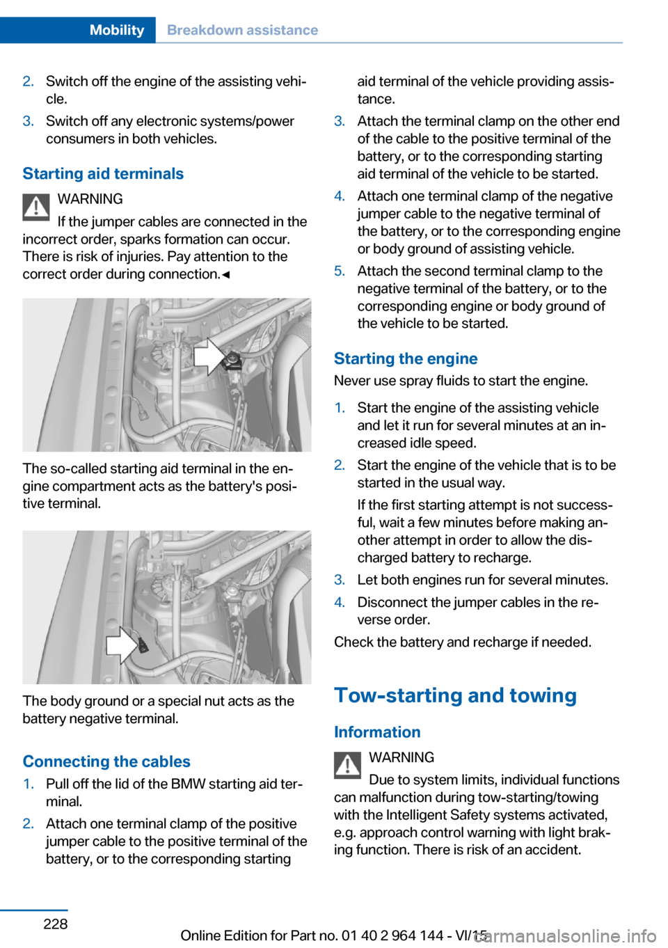
The so-called starting aid terminal in the en‐
gine compartment acts as the battery's posi‐
tive terminal.
The body ground or a special nut acts as the
battery negative terminal.
Connecting the cables
1.Pull off the lid of the BMW starting aid ter‐
minal.2.Attach one terminal clamp of the positive
jumper cable to the positive terminal of the
battery, or to the corresponding startingaid terminal of the vehicle providing assis‐
tance.3.Attach the terminal clamp on the other end
of the cable to the positive terminal of the
battery, or to the corresponding starting
aid terminal of the vehicle to be started.4.Attach one terminal clamp of the negative
jumper cable to the negative terminal of
the battery, or to the corresponding engine
or body ground of assisting vehicle.5.Attach the second terminal clamp to the
negative terminal of the battery, or to the
corresponding engine or body ground of
the vehicle to be started.
Starting the engine
Never use spray fluids to start the engine.
1.Start the engine of the assisting vehicle
and let it run for several minutes at an in‐
creased idle speed.2.Start the engine of the vehicle that is to be
started in the usual way.
If the first starting attempt is not success‐
ful, wait a few minutes before making an‐
other attempt in order to allow the dis‐
charged battery to recharge.3.Let both engines run for several minutes.4.Disconnect the jumper cables in the re‐
verse order.
Check the battery and recharge if needed.
Tow-starting and towing Information WARNING
Due to system limits, individual functions
can malfunction during tow-starting/towing
with the Intelligent Safety systems activated,
e.g. approach control warning with light brak‐
ing function. There is risk of an accident.
Seite 228MobilityBreakdown assistance228
Online Edition for Part no. 01 40 2 964 144 - VI/15
Page 229 of 253

Switch all Intelligent Safety systems off prior to
tow-starting/towing.◀
Steptronic transmission: transporting
your vehicle
Information CAUTION
The vehicle can be damaged when tow‐
ing the vehicle with a single lifted axle. There is
risk of property damage. The vehicle should
only be transported on a loading platform.◀
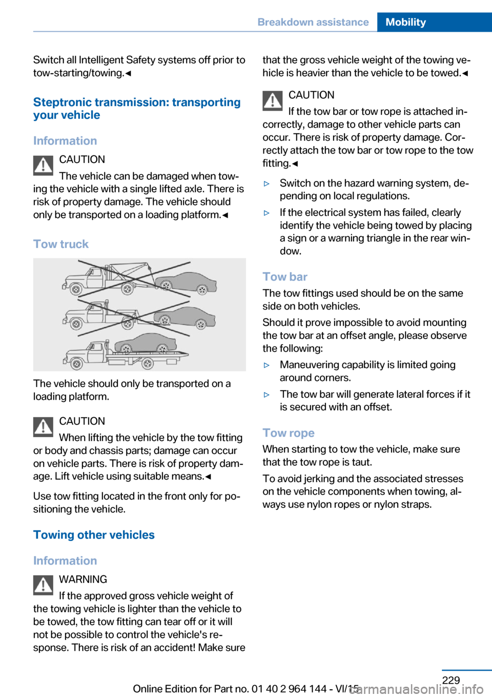
Tow truck
The vehicle should only be transported on a
loading platform.
CAUTION
When lifting the vehicle by the tow fitting
or body and chassis parts; damage can occur
on vehicle parts. There is risk of property dam‐
age. Lift vehicle using suitable means.◀
Use tow fitting located in the front only for po‐
sitioning the vehicle.
Towing other vehicles
Information WARNING
If the approved gross vehicle weight of
the towing vehicle is lighter than the vehicle to be towed, the tow fitting can tear off or it will
not be possible to control the vehicle's re‐
sponse. There is risk of an accident! Make sure
that the gross vehicle weight of the towing ve‐
hicle is heavier than the vehicle to be towed.◀
CAUTION
If the tow bar or tow rope is attached in‐
correctly, damage to other vehicle parts can
occur. There is risk of property damage. Cor‐
rectly attach the tow bar or tow rope to the tow
fitting.◀▷Switch on the hazard warning system, de‐
pending on local regulations.▷If the electrical system has failed, clearly
identify the vehicle being towed by placing
a sign or a warning triangle in the rear win‐
dow.
Tow bar
The tow fittings used should be on the same
side on both vehicles.
Should it prove impossible to avoid mounting
the tow bar at an offset angle, please observe
the following:
▷Maneuvering capability is limited going
around corners.▷The tow bar will generate lateral forces if it
is secured with an offset.
Tow rope
When starting to tow the vehicle, make sure
that the tow rope is taut.
To avoid jerking and the associated stresses
on the vehicle components when towing, al‐
ways use nylon ropes or nylon straps.
Seite 229Breakdown assistanceMobility229
Online Edition for Part no. 01 40 2 964 144 - VI/15