2016 BMW X1 warning light
[x] Cancel search: warning lightPage 198 of 242

CAUTION
Folded-away wipers can be jammed
when the hood is opened. There is risk of
property damage. Make sure that the wipers
with the wiper blades mounted are folded
down onto the windshield before opening the
hood.◀
WARNING
There are protruding parts, e.g. lock
hook, on the inside of the hood. There is risk of
injuries. If the hood is open, pay attention to
protruding parts and keep these areas clear.◀
WARNING
An incorrectly locked hood can open
while driving and restrict visibility. There is risk
of an accident. Stop immediately and correctly
close the hood.◀
WARNING
Body parts can be jammed on opening
and closing the hood. There is risk of injuries.
Make sure that the area of movement of the
hood is clear during opening and closing.◀
Opening the hood1.Pull lever, arrow 1.
Hood is unlocked.2.After the lever is released, pull the lever
again, arrow 2.
Hood can be opened.Indicator/warning lights
When the hood is unlocked, a Check Control
message is displayed.
Closing the hood1.Let the hood fall from approx. 16 in/40 cm
height, arrow 1.
The hood must audibly engage on both
sides.2.If necessary, apply even pressure in the
area of the hood latches, arrows 2, to com‐
pletely secure the hood again.Seite 198MobilityEngine compartment198
Online Edition for Part no. 01 40 2 964 303 - VI/15
Page 202 of 242

CoolantVehicle features and optionsThis chapter describes all standard, country-
specific and optional features offered with the
series. It also describes features that are not
necessarily available in your car, e. g., due to
the selected options or country versions. This
also applies to safety-related functions and
systems. The respectively applicable country
provisions must be observed when using the
respective features and systems.
Information WARNING
With the engine hot and the cooling sys‐
tem open, coolant can escape and lead to
burns. There is risk of injuries. Only open the
cooling system with the engine cooled down.◀
WARNING
Additives are harmful and incorrect addi‐
tives can damage the engine. There is risk of
injuries and risk of property damage. Avoid the
contact of articles of clothing, skin or eyes with
additives. Do not swallow any additives. Use
suitable additives only.◀
Coolant consists of water and additives.
Not all commercially available additives are
suitable for the vehicle. Information about suit‐
able additives is available from a dealer’s serv‐
ice center or another qualified service center or
repair shop.
Coolant level
Overview
Depending on the engine installation, the cool‐
ant reservoir is located on the right side or the
left side of the engine compartment.Checking
There are yellow Min and Max marks in the
coolant reservoir.1.Let the engine cool.2.Turn the lid of the coolant reservoir slightly
counterclockwise to allow any excess
pressure to dissipate, then open it.3.Open the coolant reservoir lid.4.The coolant level is correct if it lies be‐
tween the minimum and maximum marks
in the filler neck.
Adding
1.Let the engine cool.2.Turn the lid of the coolant reservoir slightly
counterclockwise to allow any excess
pressure to dissipate, then open it.3.If the coolant is low, slowly add coolant up
to the specified level; do not overfill.Seite 202MobilityCoolant202
Online Edition for Part no. 01 40 2 964 303 - VI/15
Page 205 of 242

Socket for OBD Onboard
Diagnosis
Information CAUTION
Improper use of the socket for Onboard
Diagnosis can lead to vehicle malfunctions.
There is risk of property damage. The manu‐
facturer of your vehicle strongly recommends
access to the socket for Onboard Diagnosis be
limited to a dealer's service center, another
qualified service center or repair shop or other
authorized persons.◀
Position
There is an OBD socket on the driver's side for
checking the primary components in the vehi‐
cle's emissions.
Emissions
▷The warning lamp lights up:
Emissions are deteriorating. Have
the vehicle checked as soon as
possible.▷The warning lamp flashes under certain
circumstances:
This indicates that there is excessive mis‐
firing in the engine.
Reduce the vehicle speed and have the
system checked immediately; otherwise,
serious engine misfiring within a brief pe‐
riod can seriously damage emission con‐trol components, in particular the catalytic
converter.Seite 205MaintenanceMobility205
Online Edition for Part no. 01 40 2 964 303 - VI/15
Page 207 of 242

A spare lamp box is available from a dealer’s
service center or another qualified service cen‐
ter or repair shop.
WARNING
Bulbs can get hot during operation. Con‐
tact with the bulbs can cause burns. There is
risk of injuries. Only change bulbs after they
have cooled off.◀
WARNING
Work on switched-on lighting systems
can cause short circuits. There is risk of inju‐
ries or risk of property damage. When working
on the lighting system, switch off the lamps in
question. If necessary, heed the bulb manufac‐
turer's instructions.◀
CAUTION
Contaminated bulbs reduce their service
life. There is risk of property damage. Do not
hold new bulbs with your bare hands. Use a
clean cloth or something similar, or hold the
bulb by its base.◀
Light-emitting diodes (LEDs)
Some items of equipment use light-emitting
diodes installed behind a cover as a light
source.
These light-emitting diodes, which are related
to conventional lasers, are officially designated
as Class 1 light-emitting diodes.
WARNING
Too intensive brightness can irritate or
damage the retina of the eye. There is risk of
injuries. Do not look directly into the headlights
or other light sources for an extended period of
time. Do not remove the LED covers.◀
Headlight glass
Condensation can form on the inside of the ex‐
ternal lights in cool or humid weather. When
driving with the lights switched on, the con‐
densation evaporates after a short time. The
headlight glass does not need to be changed.If despite driving with the lights switched on,
increasing humidity forms, e. g. water droplets
in the lamp, the manufacturer of your vehicle
recommends having it checked by a dealer’s
service center or another qualified service cen‐
ter or repair shop.
Headlight setting
The headlight adjustments can be affected by
changing lights and bulbs. After the headlight
adjustment was changed, have it checked and,
if necessary, corrected by a dealer’s service
center or another qualified service center or re‐
pair shop.
Front lights, bulb replacement
Halogen headlights Overview1High beams, headlight flasher2Low beams3Side marker lights4Turn signal5Parking lights / daytime running lights6Parking lights / daytime running lights
Parking lights, daytime running lights
The parking lights and daylight running lights
are made using LED technology.
Contact a dealer’s service center or another
qualified service center or repair shop in the
event of a malfunction.
Seite 207Replacing componentsMobility207
Online Edition for Part no. 01 40 2 964 303 - VI/15
Page 213 of 242

2.Press the nonworking bulb gently into the
socket, turn counterclockwise and remove.▷Upper bulb: reversing lamp▷Lower bulb: inner brake lamp
Only vehicles with halogen headlights:
▷Lower bulb, 5-watt: tail light
Installing the bulb holder
1.Proceed in the reverse order to insert the
new bulb and attach the bulb holder.
Connect the plug to the bulb holder.2.Make sure that the bulb holder is correctly
and firmly seated.
Central brake lamp and license plate
lamp
Follow general instructions, refer to page 206.
These lights are made using LED technology.
Contact a dealer’s service center or another
qualified service center or repair shop in the
event of a malfunction.
Changing wheels
Information When using run-flat tires or sealants, a tire
does not need to be changed immediately in
the event of pressure loss due to a flat tire.
Which is why no spare tire is available.
The tools for changing wheels are available as
accessories from your dealer’s service center
or another qualified service center or repair
shop.
Jacking points for the vehicle jack
The jacking points for the vehicle jack are lo‐
cated at the positions shown.
Emergency wheel
Safety measures
▷Park the vehicle as far away as possible
from passing traffic and on solid ground.
Switch on the hazard warning system.▷Set the parking brake and engage lever in
position P P.▷Have all vehicle occupants get out of the
vehicle and ensure that they remain out‐
side the immediate area in a safe place,
such as behind a guardrail.▷If necessary, set up a warning triangle or
portable hazard warning lamp at an appro‐
priate distance.▷Perform wheel change only on a flat, solid
and slip-resistant surface. On soft or slip‐
pery ground, e.g., snow, ice, tiles, etc., the
vehicle or vehicle jack can slip away to the
side.▷Do not place wood blocks or similar items
under the vehicle jack; otherwise, it cannot
reach its carrying capacity because of the
restricted height.▷If the vehicle is raised, do not lie under the
vehicle and do not start the engine; other‐
wise, a fatal hazard exists.Seite 213Replacing componentsMobility213
Online Edition for Part no. 01 40 2 964 303 - VI/15
Page 214 of 242

InformationWARNING
The vehicle jack is optimized for lifting
the vehicle and for the jacking points on the
vehicle only. There is risk of injuries. Do not lift
any other vehicle or cargo using the vehicle
jack.◀
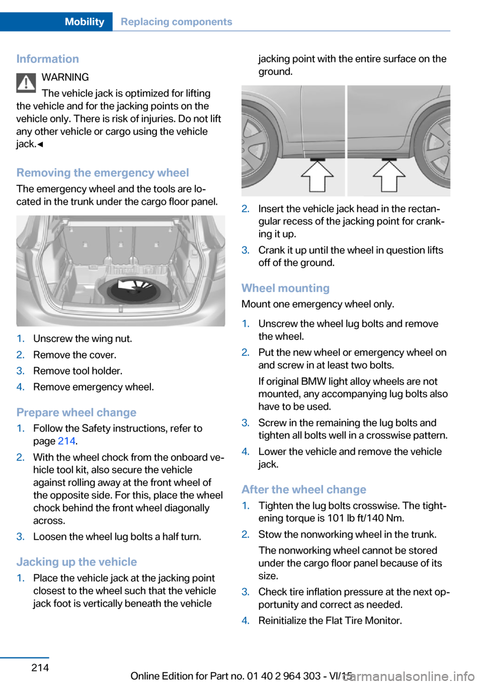
Removing the emergency wheel The emergency wheel and the tools are lo‐
cated in the trunk under the cargo floor panel.1.Unscrew the wing nut.2.Remove the cover.3.Remove tool holder.4.Remove emergency wheel.
Prepare wheel change
1.Follow the Safety instructions, refer to
page 214.2.With the wheel chock from the onboard ve‐
hicle tool kit, also secure the vehicle
against rolling away at the front wheel of
the opposite side. For this, place the wheel
chock behind the front wheel diagonally
across.3.Loosen the wheel lug bolts a half turn.
Jacking up the vehicle
1.Place the vehicle jack at the jacking point
closest to the wheel such that the vehicle
jack foot is vertically beneath the vehiclejacking point with the entire surface on the
ground.2.Insert the vehicle jack head in the rectan‐
gular recess of the jacking point for crank‐
ing it up.3.Crank it up until the wheel in question lifts
off of the ground.
Wheel mounting
Mount one emergency wheel only.
1.Unscrew the wheel lug bolts and remove
the wheel.2.Put the new wheel or emergency wheel on
and screw in at least two bolts.
If original BMW light alloy wheels are not
mounted, any accompanying lug bolts also
have to be used.3.Screw in the remaining the lug bolts and
tighten all bolts well in a crosswise pattern.4.Lower the vehicle and remove the vehicle
jack.
After the wheel change
1.Tighten the lug bolts crosswise. The tight‐
ening torque is 101 lb ft/140 Nm.2.Stow the nonworking wheel in the trunk.
The nonworking wheel cannot be stored
under the cargo floor panel because of its
size.3.Check tire inflation pressure at the next op‐
portunity and correct as needed.4.Reinitialize the Flat Tire Monitor.Seite 214MobilityReplacing components214
Online Edition for Part no. 01 40 2 964 303 - VI/15
Page 217 of 242

Breakdown assistanceVehicle features and options
This chapter describes all standard, country-
specific and optional features offered with the
series. It also describes features that are not
necessarily available in your car, e. g., due to
the selected options or country versions. This
also applies to safety-related functions and
systems. The respectively applicable country
provisions must be observed when using the
respective features and systems.
Hazard warning flashers
The button is located in the center console.
Intelligent Emergency
Request
The concept In case of an emergency, an Emergency Re‐
quest can be made through this system.
General information
Only press the SOS button in an emergency.
For technical reasons, the Emergency Request
cannot be guaranteed under unfavorable con‐
ditions.
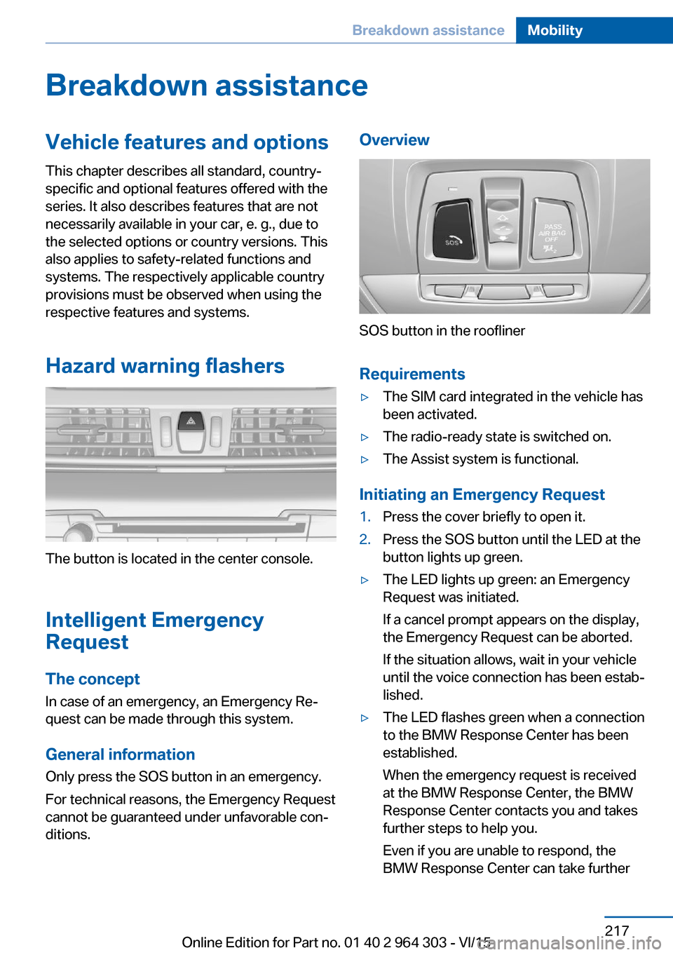
Overview
SOS button in the roofliner
Requirements
▷The SIM card integrated in the vehicle has
been activated.▷The radio-ready state is switched on.▷The Assist system is functional.
Initiating an Emergency Request
1.Press the cover briefly to open it.2.Press the SOS button until the LED at the
button lights up green.▷The LED lights up green: an Emergency
Request was initiated.
If a cancel prompt appears on the display,
the Emergency Request can be aborted.
If the situation allows, wait in your vehicle
until the voice connection has been estab‐
lished.▷The LED flashes green when a connection
to the BMW Response Center has been
established.
When the emergency request is received
at the BMW Response Center, the BMW
Response Center contacts you and takes
further steps to help you.
Even if you are unable to respond, the
BMW Response Center can take furtherSeite 217Breakdown assistanceMobility217
Online Edition for Part no. 01 40 2 964 303 - VI/15
Page 219 of 242

Starting aid terminalsWARNING
If the jumper cables are connected in the
incorrect order, sparks formation can occur.
There is risk of injuries. Pay attention to the
correct order during connection.◀
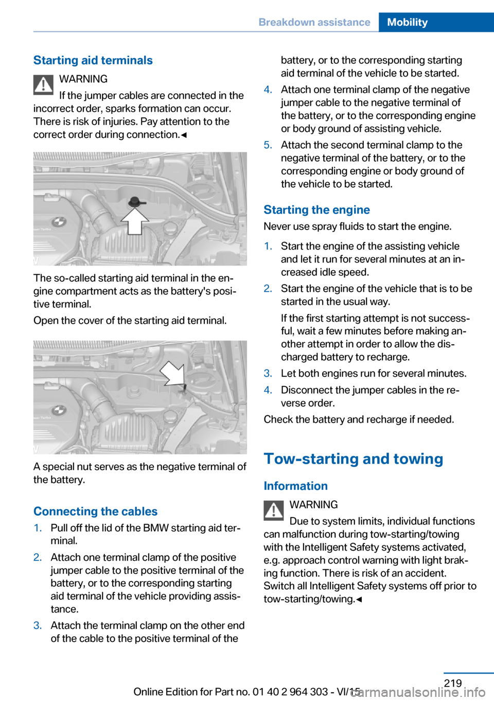
The so-called starting aid terminal in the en‐
gine compartment acts as the battery's posi‐
tive terminal.
Open the cover of the starting aid terminal.
A special nut serves as the negative terminal of
the battery.
Connecting the cables
1.Pull off the lid of the BMW starting aid ter‐
minal.2.Attach one terminal clamp of the positive
jumper cable to the positive terminal of the
battery, or to the corresponding starting
aid terminal of the vehicle providing assis‐
tance.3.Attach the terminal clamp on the other end
of the cable to the positive terminal of thebattery, or to the corresponding starting
aid terminal of the vehicle to be started.4.Attach one terminal clamp of the negative
jumper cable to the negative terminal of
the battery, or to the corresponding engine
or body ground of assisting vehicle.5.Attach the second terminal clamp to the
negative terminal of the battery, or to the
corresponding engine or body ground of
the vehicle to be started.
Starting the engine
Never use spray fluids to start the engine.
1.Start the engine of the assisting vehicle
and let it run for several minutes at an in‐
creased idle speed.2.Start the engine of the vehicle that is to be
started in the usual way.
If the first starting attempt is not success‐
ful, wait a few minutes before making an‐
other attempt in order to allow the dis‐
charged battery to recharge.3.Let both engines run for several minutes.4.Disconnect the jumper cables in the re‐
verse order.
Check the battery and recharge if needed.
Tow-starting and towing Information WARNING
Due to system limits, individual functions
can malfunction during tow-starting/towing
with the Intelligent Safety systems activated,
e.g. approach control warning with light brak‐
ing function. There is risk of an accident.
Switch all Intelligent Safety systems off prior to
tow-starting/towing.◀
Seite 219Breakdown assistanceMobility219
Online Edition for Part no. 01 40 2 964 303 - VI/15