2016 BMW M4 CONVERTIBLE steering
[x] Cancel search: steeringPage 119 of 226

Brake force display
The concept▷During normal brake application, the outer
brake lights light up.▷During heavy brake application, the inner
brake lights light up in addition.
Attentiveness assistant
The concept The system can detect increasing lack of alert‐
ness or fatigue of the driver during long, mo‐
notonous journeys, e.g., on highways. In this
situation, it is recommended that the driver
takes a break.
Note Personal responsibility
The system cannot act as a substitute for
the personal assessment of one's physical
state and may not detect an increasing lack of
alertness or fatigue or may not detect it cor‐
rectly. Therefore, make sure that the driver is
rested and alert; otherwise, risks may be de‐
tected too late and an accident be caused as a
result.◀
Function
The system is activated each time the engine
is started and cannot be switched off.
After travel has begun, the system is trained
about the driver, so that increasing lack of
alertness or fatigue can be detected.
This procedure takes the following criteria into
account:▷Personal driving style, e.g., steering behav‐
ior.▷Driving conditions, e.g., length of trip.
Starting at approximately 43 mph/70 km/h, the
system is active and can display a recommen‐
dation to take a break.
Break recommendation
If the driver becomes increasingly less alert or
fatigued, a message is displayed in the Control
Display with the recommendation to take a
break.
A recommendation to take a break is displayed
only once during an uninterrupted trip.
After a break, another recommendation to take
a break cannot be displayed until after approxi‐
mately 45 minutes.
System limits
The function may be limited in the following
situations, for instance, and will either output
an incorrect warning or no warning at all:
▷When the clock is set incorrectly.▷When the vehicle speed is mainly below
about 43 mph/70 km/h.▷With a sporty driving style, such as during
rapid acceleration or when cornering fast.▷In active driving situations, such as when
changing lanes frequently.▷When the road surface is poor.▷In the event of strong side winds.Seite 115SafetyControls115
Online Edition for Part no. 01 40 2 960 812 - II/15
Page 120 of 226
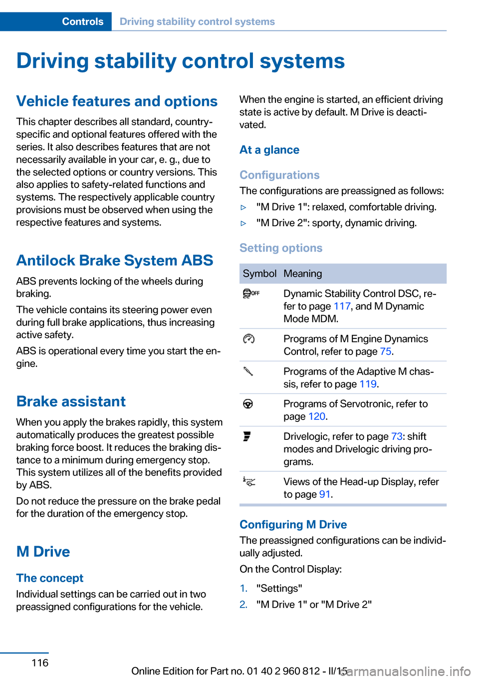
Driving stability control systemsVehicle features and optionsThis chapter describes all standard, country-
specific and optional features offered with the
series. It also describes features that are not
necessarily available in your car, e. g., due to
the selected options or country versions. This
also applies to safety-related functions and
systems. The respectively applicable country
provisions must be observed when using the
respective features and systems.
Antilock Brake System ABS ABS prevents locking of the wheels during
braking.
The vehicle contains its steering power even
during full brake applications, thus increasing
active safety.
ABS is operational every time you start the en‐
gine.
Brake assistant When you apply the brakes rapidly, this system
automatically produces the greatest possible
braking force boost. It reduces the braking dis‐
tance to a minimum during emergency stop.
This system utilizes all of the benefits provided
by ABS.
Do not reduce the pressure on the brake pedal
for the duration of the emergency stop.
M Drive The conceptIndividual settings can be carried out in two
preassigned configurations for the vehicle.When the engine is started, an efficient driving
state is active by default. M Drive is deacti‐
vated.
At a glance
Configurations
The configurations are preassigned as follows:▷"M Drive 1": relaxed, comfortable driving.▷"M Drive 2": sporty, dynamic driving.
Setting options
SymbolMeaning Dynamic Stability Control DSC, re‐
fer to page 117, and M Dynamic
Mode MDM. Programs of M Engine Dynamics
Control, refer to page 75. Programs of the Adaptive M chas‐
sis, refer to page 119. Programs of Servotronic, refer to
page 120. Drivelogic, refer to page 73: shift
modes and Drivelogic driving pro‐
grams. Views of the Head-up Display, refer
to page 91.
Configuring M Drive
The preassigned configurations can be individ‐
ually adjusted.
On the Control Display:
1."Settings"2."M Drive 1" or "M Drive 2"Seite 116ControlsDriving stability control systems116
Online Edition for Part no. 01 40 2 960 812 - II/15
Page 122 of 226
Do not deactivate DSC when driving with
roof load
Do not deactivate Dynamic Stability Control
DSC when driving with roof load, e.g. roof-
mounted luggage rack.
Otherwise, driving safety is not given in driv‐
ing-critical situation due to the elevated center
of gravity.◀
Overview
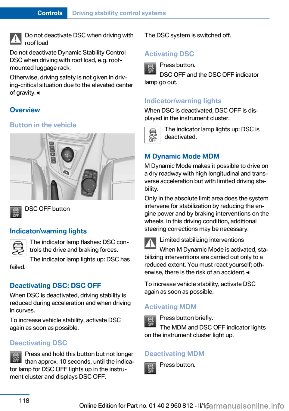
Button in the vehicle
DSC OFF button
Indicator/warning lights The indicator lamp flashes: DSC con‐
trols the drive and braking forces.
The indicator lamp lights up: DSC has
failed.
Deactivating DSC: DSC OFF
When DSC is deactivated, driving stability is
reduced during acceleration and when driving
in curves.
To increase vehicle stability, activate DSC
again as soon as possible.
Deactivating DSC Press and hold this button but not longer
than approx. 10 seconds, until the indica‐
tor lamp for DSC OFF lights up in the instru‐
ment cluster and displays DSC OFF.
The DSC system is switched off.
Activating DSC Press button.
DSC OFF and the DSC OFF indicator
lamp go out.
Indicator/warning lights
When DSC is deactivated, DSC OFF is dis‐
played in the instrument cluster.
The indicator lamp lights up: DSC is
deactivated.
M Dynamic Mode MDM
M Dynamic Mode makes it possible to drive on
a dry roadway with high longitudinal and trans‐
verse acceleration but with limited driving sta‐
bility.
Only in the absolute limit area does the system
intervene for stabilization by reducing the en‐
gine power and by braking interventions on the
wheels. In this driving condition, additional
steering corrections may be necessary.
Limited stabilizing interventions
When M Dynamic Mode is activated, sta‐
bilizing interventions are carried out only to a
reduced extent. You must react yourself; oth‐
erwise, there is the risk of an accident.◀
To increase vehicle stability, activate DSC
again as soon as possible.
Activating MDM Press button briefly.
The MDM and DSC OFF indicator lights
on the instrument cluster light up.
Deactivating MDM Press button.Seite 118ControlsDriving stability control systems118
Online Edition for Part no. 01 40 2 960 812 - II/15
Page 123 of 226
The MDM and DSC OFF indicator lights go
out.
Via M Drive On the Control Display:1."Settings"2."M Drive 1" or "M Drive 2"3. Select the symbol.4."MDM"
To open M Drive with the selected settings,
press the corresponding button on the steer‐
ing wheel:
▷▷
A message appears in the instrument cluster.
This message is confirmed by pressing the
button again.
Deactivating MDM
Press the appropriate button 1 or button 2 on
the steering wheel again.
M Dynamic Mode and the settings selected
under M Drive are deactivated.
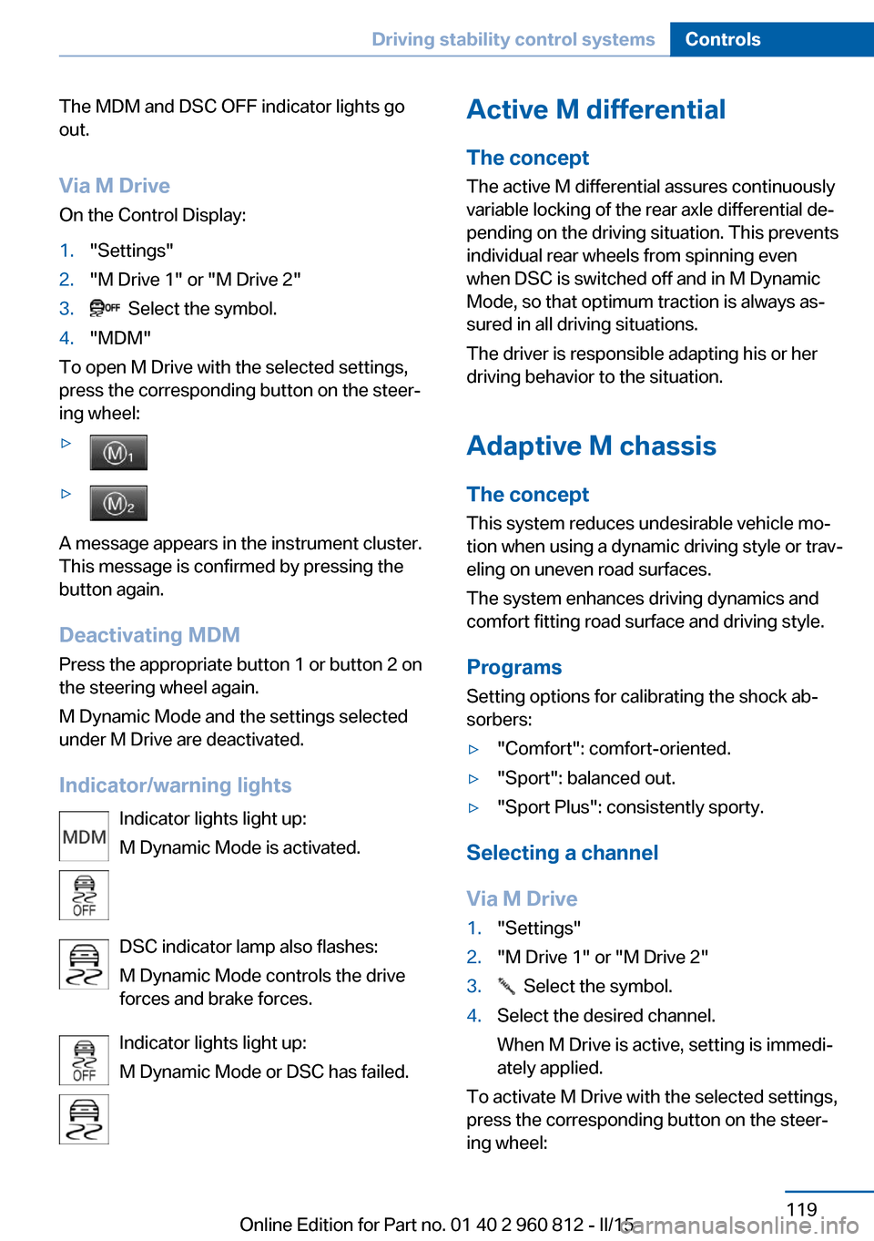
Indicator/warning lights Indicator lights light up:
M Dynamic Mode is activated.
DSC indicator lamp also flashes:
M Dynamic Mode controls the drive
forces and brake forces.
Indicator lights light up:
M Dynamic Mode or DSC has failed.
Active M differential
The concept The active M differential assures continuously
variable locking of the rear axle differential de‐
pending on the driving situation. This prevents
individual rear wheels from spinning even
when DSC is switched off and in M Dynamic
Mode, so that optimum traction is always as‐
sured in all driving situations.
The driver is responsible adapting his or her
driving behavior to the situation.
Adaptive M chassis The conceptThis system reduces undesirable vehicle mo‐
tion when using a dynamic driving style or trav‐
eling on uneven road surfaces.
The system enhances driving dynamics and
comfort fitting road surface and driving style.
Programs Setting options for calibrating the shock ab‐
sorbers:▷"Comfort": comfort-oriented.▷"Sport": balanced out.▷"Sport Plus": consistently sporty.
Selecting a channel
Via M Drive
1."Settings"2."M Drive 1" or "M Drive 2"3. Select the symbol.4.Select the desired channel.
When M Drive is active, setting is immedi‐
ately applied.
To activate M Drive with the selected settings,
press the corresponding button on the steer‐
ing wheel:
Seite 119Driving stability control systemsControls119
Online Edition for Part no. 01 40 2 960 812 - II/15
Page 124 of 226
▷▷
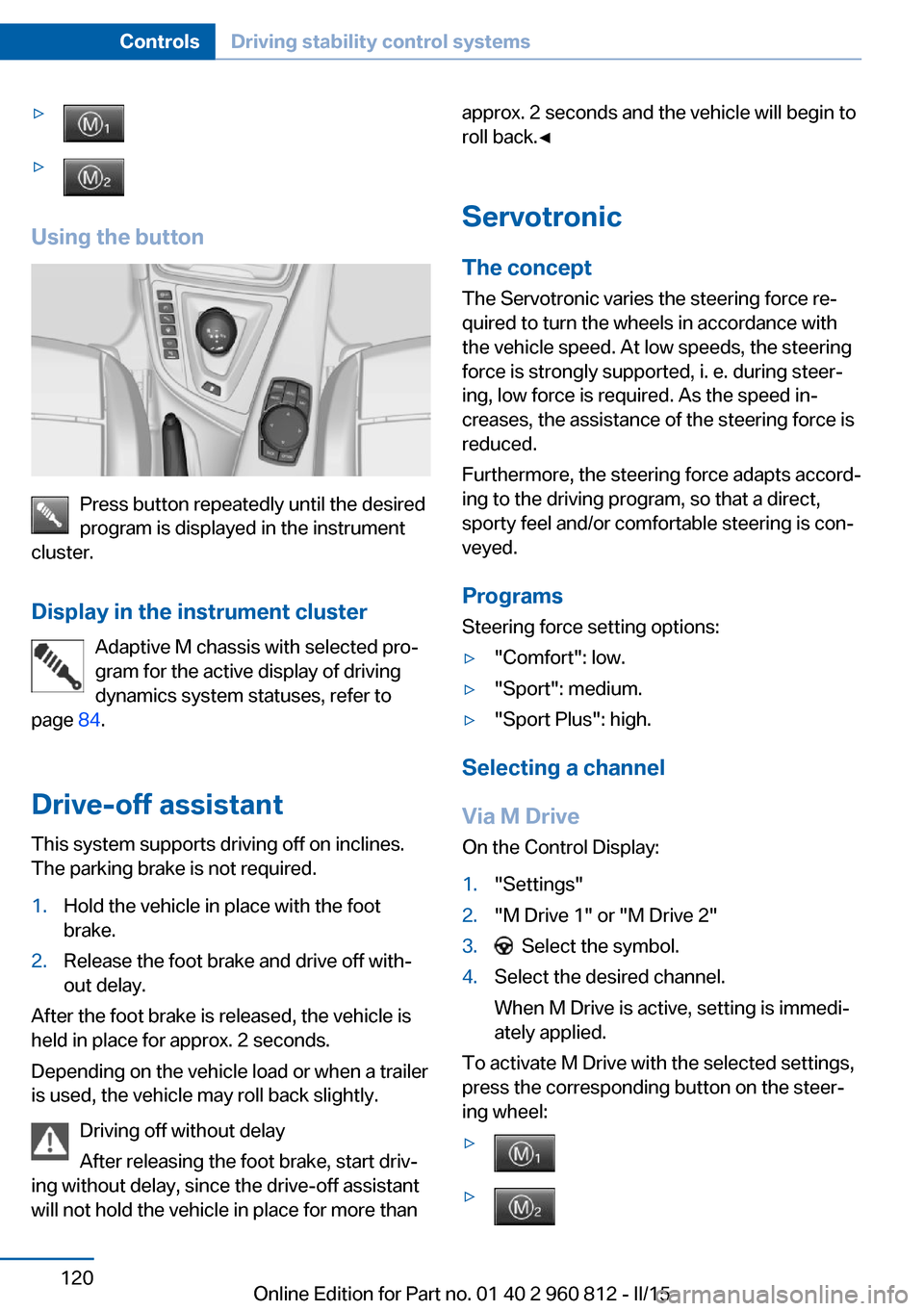
Using the button
Press button repeatedly until the desired
program is displayed in the instrument
cluster.
Display in the instrument cluster Adaptive M chassis with selected pro‐
gram for the active display of driving
dynamics system statuses, refer to
page 84.
Drive-off assistant This system supports driving off on inclines.
The parking brake is not required.
1.Hold the vehicle in place with the foot
brake.2.Release the foot brake and drive off with‐
out delay.
After the foot brake is released, the vehicle is
held in place for approx. 2 seconds.
Depending on the vehicle load or when a trailer
is used, the vehicle may roll back slightly.
Driving off without delay
After releasing the foot brake, start driv‐
ing without delay, since the drive-off assistant
will not hold the vehicle in place for more than
approx. 2 seconds and the vehicle will begin to
roll back.◀
Servotronic The conceptThe Servotronic varies the steering force re‐
quired to turn the wheels in accordance with
the vehicle speed. At low speeds, the steering
force is strongly supported, i. e. during steer‐
ing, low force is required. As the speed in‐ creases, the assistance of the steering force is
reduced.
Furthermore, the steering force adapts accord‐
ing to the driving program, so that a direct, sporty feel and/or comfortable steering is con‐
veyed.
Programs Steering force setting options:▷"Comfort": low.▷"Sport": medium.▷"Sport Plus": high.
Selecting a channel
Via M Drive On the Control Display:
1."Settings"2."M Drive 1" or "M Drive 2"3. Select the symbol.4.Select the desired channel.
When M Drive is active, setting is immedi‐
ately applied.
To activate M Drive with the selected settings,
press the corresponding button on the steer‐
ing wheel:
▷▷Seite 120ControlsDriving stability control systems120
Online Edition for Part no. 01 40 2 960 812 - II/15
Page 126 of 226

Driving comfortVehicle features and options
This chapter describes all standard, country-
specific and optional features offered with the
series. It also describes features that are not
necessarily available in your car, e. g., due to
the selected options or country versions. This
also applies to safety-related functions and
systems. The respectively applicable country
provisions must be observed when using the
respective features and systems.
Cruise control The concept The system maintains a preset speed via the
buttons on the steering wheel. The system brakes on downhill gradients if engine braking
is insufficient.
General information
Depending on the driving settings, the features
of the cruise control can change in certain
areas.
Hints Unfavorable conditions
Do not use the system if unfavorable
conditions make it impossible to drive at a con‐
stant speed, e.g.:▷On winding roads.▷In heavy traffic.▷On slippery roads, in fog, snow or rain, or
on a loose road surface.
Otherwise, you could lose control of the vehi‐
cle and cause an accident.◀
Overview
Buttons on the steering wheelPress buttonFunctionSystem on/off, interruptStore speedResume speedrocker switch: change, hold,
store speed
Controls
Switching on Press button on the steering wheel.
The marking in the speedometer is set to the
current speed.
Cruise control can be used.
Switch off Deactivated or interrupted system
With deactivated or interrupted system
use your brakes, steering and moves as usual
to avoid the chance of an accident.◀
Press button.
▷If active: press twice.▷If interrupted: press once.
The displays go out. The stored desired speed
is deleted.
Seite 122ControlsDriving comfort122
Online Edition for Part no. 01 40 2 960 812 - II/15
Page 132 of 226
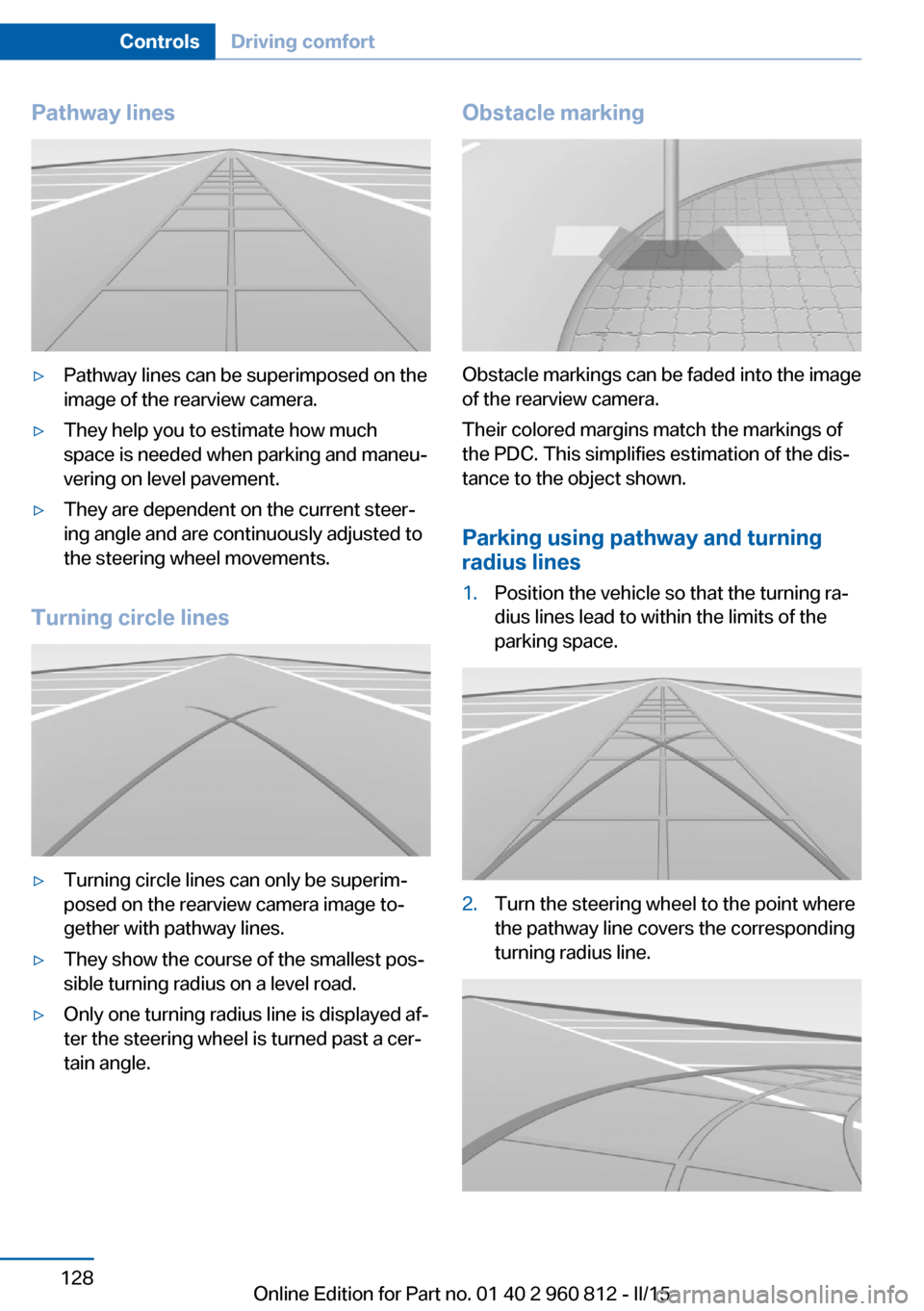
Pathway lines▷Pathway lines can be superimposed on the
image of the rearview camera.▷They help you to estimate how much
space is needed when parking and maneu‐
vering on level pavement.▷They are dependent on the current steer‐
ing angle and are continuously adjusted to
the steering wheel movements.
Turning circle lines
▷Turning circle lines can only be superim‐
posed on the rearview camera image to‐
gether with pathway lines.▷They show the course of the smallest pos‐
sible turning radius on a level road.▷Only one turning radius line is displayed af‐
ter the steering wheel is turned past a cer‐
tain angle.Obstacle marking
Obstacle markings can be faded into the image
of the rearview camera.
Their colored margins match the markings of
the PDC. This simplifies estimation of the dis‐
tance to the object shown.
Parking using pathway and turning
radius lines
1.Position the vehicle so that the turning ra‐
dius lines lead to within the limits of the
parking space.2.Turn the steering wheel to the point where
the pathway line covers the corresponding
turning radius line.Seite 128ControlsDriving comfort128
Online Edition for Part no. 01 40 2 960 812 - II/15
Page 135 of 226

Cameras
The lenses of the Top View camera are located
at the bottom in the mirror housings. The im‐
age quality may be impaired by dirt.
Clean the camera lenses, refer to page 207.
Switching on/off
Switching on automatically With the engine running, engage lever in posi‐
tion P R.
The Top View and PDC images are displayed if
the system is switched on via iDrive.
Automatic deactivation during forward
travel
The system switches off when a certain driving
distance or speed is exceeded.
Switch the system back on if needed.
Switching on/off manually Press button.
▷On: the LED lights up.▷Off: the LED goes out.
Top View is displayed.
Display
Visual warning
The approach of the vehicle to an object can
be shown on the Control Display.
When the distance to an object is small, a red
bar is shown in front of the vehicle, as it is in
the PDC display.
The display appears as soon as Top View is
activated.
When the image of the rearview camera is dis‐
played, it is possible to reel to top view:
"Rear view camera"
Brightness
With Top View switched on:
1. Select the symbol.2.Turn the controller until the desired setting
is reached, and press the controller.
Contrast
With Top View switched on:
1. Select the symbol.2.Turn the controller until the desired setting
is reached, and press the controller.
Displaying the turning radius and
pathway lines
▷The static, red turning radius line shows
the space needed to the side of the vehicle
when the steering wheel is turned all the
way.▷The variable, green pathway line assists
you in assessing the amount of space ac‐
tually needed to the side of the vehicle.
The lane line depends on the engaged
gear and the current steering angle. TheSeite 131Driving comfortControls131
Online Edition for Part no. 01 40 2 960 812 - II/15