2016 BMW M4 CONVERTIBLE trunk
[x] Cancel search: trunkPage 150 of 226

NoteThe total load of all sockets must not exceed
140 watts at 12 volts.
Do not damage the socket by using unsuitable
connectors.
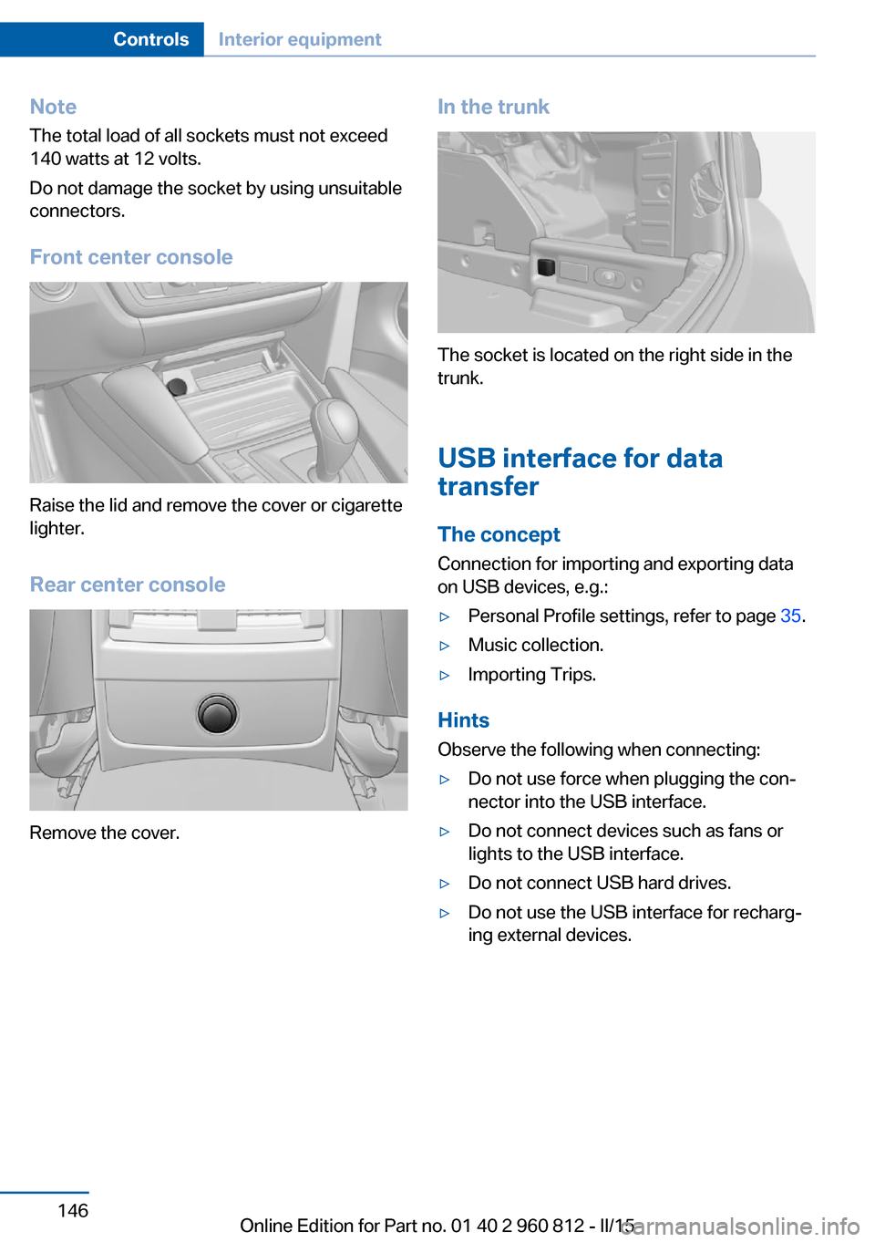
Front center console
Raise the lid and remove the cover or cigarette
lighter.
Rear center console
Remove the cover.
In the trunk
The socket is located on the right side in the
trunk.
USB interface for data
transfer
The concept
Connection for importing and exporting data
on USB devices, e.g.:
▷Personal Profile settings, refer to page 35.▷Music collection.▷Importing Trips.
Hints
Observe the following when connecting:
▷Do not use force when plugging the con‐
nector into the USB interface.▷Do not connect devices such as fans or
lights to the USB interface.▷Do not connect USB hard drives.▷Do not use the USB interface for recharg‐
ing external devices.Seite 146ControlsInterior equipment146
Online Edition for Part no. 01 40 2 960 812 - II/15
Page 152 of 226

Expanding cargo area volume
With the hardtop closed, the cargo area vol‐
ume can be expanded. To do this, push the
cargo area partition upward.
Loading aid
Hints Operation of the loading aid
Before operating the loading aid, make
sure that the movement area of the loading aid
is clear. During the lowering or raising of the
loading aid, do not reach into the mechanism.
Keep persons away from the area of move‐
ment of the loading aid. Otherwise, damages
or personal injuries may result.◀
Raised loading aid
Do not drive with the loading aid raised.
Before driving off, make sure that the loading
aid is completely lowered and the trunk lid is
closed. Otherwise, damage may result.◀
Functional requirements
▷Vehicle at a standstill.▷Vehicle is on a level surface.▷Hardtop fully open.▷Trunk lid fully open.▷Cargo area partition latched in the lower
position.▷External temperature not below +14 ℉/–
10 ℃.Controls
Open trunk lid all the way.
Press left button: loading aid is
raised.
Press right button: loading aid is
lowered.
The movement is executed at
different speeds depending on the external
temperature.
The movement stops with the release of the
button.
LED in button:
▷Lights up continuously: loading aid in the
respective limit position.▷Flashes fast: loading aid not in the respec‐
tive end position.▷Flashes slowly: functional requirements
not met.
A Check Control message is displayed.
After switching off the ignition, the raised load‐
ing aid can be lowered within approx. 10 mi‐
nutes. After that, the ignition must be switched
on for lowering.
Use the loading aid only for loading and un‐
loading the trunk.
Always move the loading aid into the limit posi‐
tions.
Do not park the vehicle with the loading aid
raised.
The trunk lid can only be closed when the
loading aid is fully lowered.
Seite 148ControlsInterior equipment148
Online Edition for Part no. 01 40 2 960 812 - II/15
Page 163 of 226

General driving notes
Closing the trunk lid Drive with the trunk lid closed
Only drive with the tailgate closed; other‐
wise, in the event of an accident or braking and
evasive maneuvers, passengers and other traf‐
fic may be injured, and the vehicle may be
damaged. In addition, exhaust fumes may en‐
ter the vehicle interior.◀
If driving with the tailgate open cannot be avoided:▷If the hardtop is closed, close all windows.▷Greatly increase the air flow from the vents.▷Drive moderately.
Hot exhaust system
Hot exhaust system
High temperatures are generated in the
exhaust system.
Do not remove the heat shields installed and
never apply undercoating to them. Make sure
that flammable materials, e. g. hay, leaves,
grass, etc. do not come in contact with the hot
exhaust system while driving, while in idle po‐
sition mode, or when parked. Such contact
could lead to a fire, resulting in an increased
risk of serious personal injury as well as prop‐
erty damage.
Do not touch hot exhaust pipes; otherwise,
there is a danger of getting burned.◀
Mobile communication devices in the
vehicle
Mobile communication devices in the ve‐
hicle
It is not recommended to use mobile phones,
such as mobile phones, in the vehicle interior
without a direct connection to an external aer‐
ial. Otherwise, the vehicle's electronics and
mobile communication devices can interfere
with each other. In addition, there is no assur‐
ance that the radiation generated during trans‐
mission will be conducted away from the vehi‐
cle interior.◀
Hydroplaning Hydroplaning
When driving on wet or slushy roads, re‐
duce your speed to prevent hydroplaning.◀
On wet or slushy roads, a wedge of water can
form between the tires and road surface.
This phenomenon is referred to as hydroplan‐
ing. It is characterized by a partial or complete
loss of contact between the tires and the road
surface, ultimately undermining your ability to
steer and brake the vehicle.
Driving through water Observe water level and speed
Do not exceed the maximum water level
and maximum speed; otherwise, the vehicle's
engine, the electrical systems and the trans‐
mission may be damaged.◀
Drive though calm water only and only if it is
not deeper than 9.8 inches/25 cm and at this
height, no faster than walking speed, up to 3 mph/5 km/h.
Braking safely
Your vehicle is equipped with ABS as a stand‐
ard feature.
Applying the brakes fully is the most effective
way of braking in situations needed.
Steering is still responsive. You can still avoid
any obstacles with a minimum of steering ef‐
fort.
The pulsing of the brake pedal indicates that
ABS is in its active mode.
In certain braking situations, the perforated
brake discs can cause functional problems.
However, this has no effect on the perform‐
ance and operational reliability of the brake.Seite 159Things to remember when drivingDriving tips159
Online Edition for Part no. 01 40 2 960 812 - II/15
Page 167 of 226

Load
The maximum load is the sum of the weight of
the occupants and the cargo.
The greater the weight of the occupants, the
less cargo that can be transported.
Stowing cargo
▷Cover sharp edges and corners on the
cargo.▷Heavy cargo: stow as far forward as possi‐
ble, directly behind and at the bottom of
the rear passenger seat backrests.▷Very heavy cargo: when the rear seat is not
occupied, secure each of the outer safety
belts in the opposite buckle.▷If necessary, fold down the rear backrests
to stow cargo.▷Use loading aid, refer to page 148, for eas‐
ier loading.▷Using the trunk, refer to page 48.▷Do not stack cargo above the top edge of
the backrests.Securing cargo
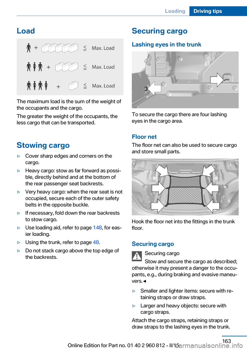
Lashing eyes in the trunk
To secure the cargo there are four lashing
eyes in the cargo area.
Floor net
The floor net can also be used to secure cargo
and store small parts.
Hook the floor net into the fittings in the trunk
floor.
Securing cargo Securing cargo
Stow and secure the cargo as described;
otherwise it may present a danger to the occu‐
pants, e.g., during braking and evasive maneu‐
vers.◀
▷Smaller and lighter items: secure with re‐
taining straps or draw straps.▷Larger and heavy objects: secure with
cargo straps.
Attach the cargo straps, retaining straps or
draw straps to the lashing eyes in the trunk.
Seite 163LoadingDriving tips163
Online Edition for Part no. 01 40 2 960 812 - II/15
Page 172 of 226

RefuelingVehicle features and options
This chapter describes all standard, country-
specific and optional features offered with the
series. It also describes features that are not
necessarily available in your car, e. g., due to
the selected options or country versions. This
also applies to safety-related functions and
systems. The respectively applicable country
provisions must be observed when using the
respective features and systems.
Hints Observe the fuel recommendation, refer to
page 170, prior to refueling.
Refuel promptly
Refuel no later than at a range of
30 miles/50 km or engine operation might fail
and damage might occur.◀
Fuel lid Opening1.Briefly press the rear edge of the fuel filler
flap.2.Turn the tank lid counterclockwise.3.Place the tank lid in the bracket attached to
the fuel filler flap.
Closing
1.Fit the lid and turn it clockwise until you
clearly hear a click.2.Close the fuel filler flap.
Do not pinch the retaining strap
Do not pinch the retaining strap attached
to the lid; otherwise, the lid cannot be closed
properly and fuel vapors can escape.◀
Manually unlocking fuel filler flap In the event of an electrical malfunction, e.g.
The release is located in the trunk.
Seite 168MobilityRefueling168
Online Edition for Part no. 01 40 2 960 812 - II/15
Page 197 of 226

Contact your service center in the event of a
malfunction.
Turn signal in exterior mirrorFollow general instructions, refer to page 190.
The turn signals in the exterior mirrors feature
LED technology. Contact your service center in the event of a malfunction.
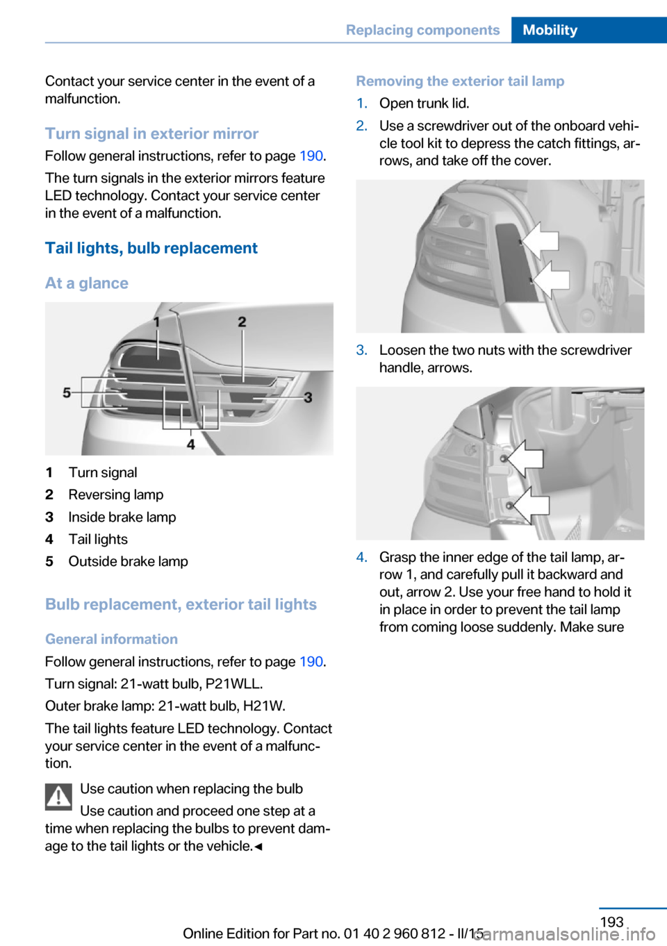
Tail lights, bulb replacement
At a glance1Turn signal2Reversing lamp3Inside brake lamp4Tail lights5Outside brake lamp
Bulb replacement, exterior tail lights General information
Follow general instructions, refer to page 190.
Turn signal: 21-watt bulb, P21WLL.
Outer brake lamp: 21-watt bulb, H21W.
The tail lights feature LED technology. Contact
your service center in the event of a malfunc‐
tion.
Use caution when replacing the bulb
Use caution and proceed one step at a
time when replacing the bulbs to prevent dam‐
age to the tail lights or the vehicle.◀
Removing the exterior tail lamp1.Open trunk lid.2.Use a screwdriver out of the onboard vehi‐
cle tool kit to depress the catch fittings, ar‐
rows, and take off the cover.3.Loosen the two nuts with the screwdriver
handle, arrows.4.Grasp the inner edge of the tail lamp, ar‐
row 1, and carefully pull it backward and
out, arrow 2. Use your free hand to hold it
in place in order to prevent the tail lamp
from coming loose suddenly. Make sureSeite 193Replacing componentsMobility193
Online Edition for Part no. 01 40 2 960 812 - II/15
Page 198 of 226

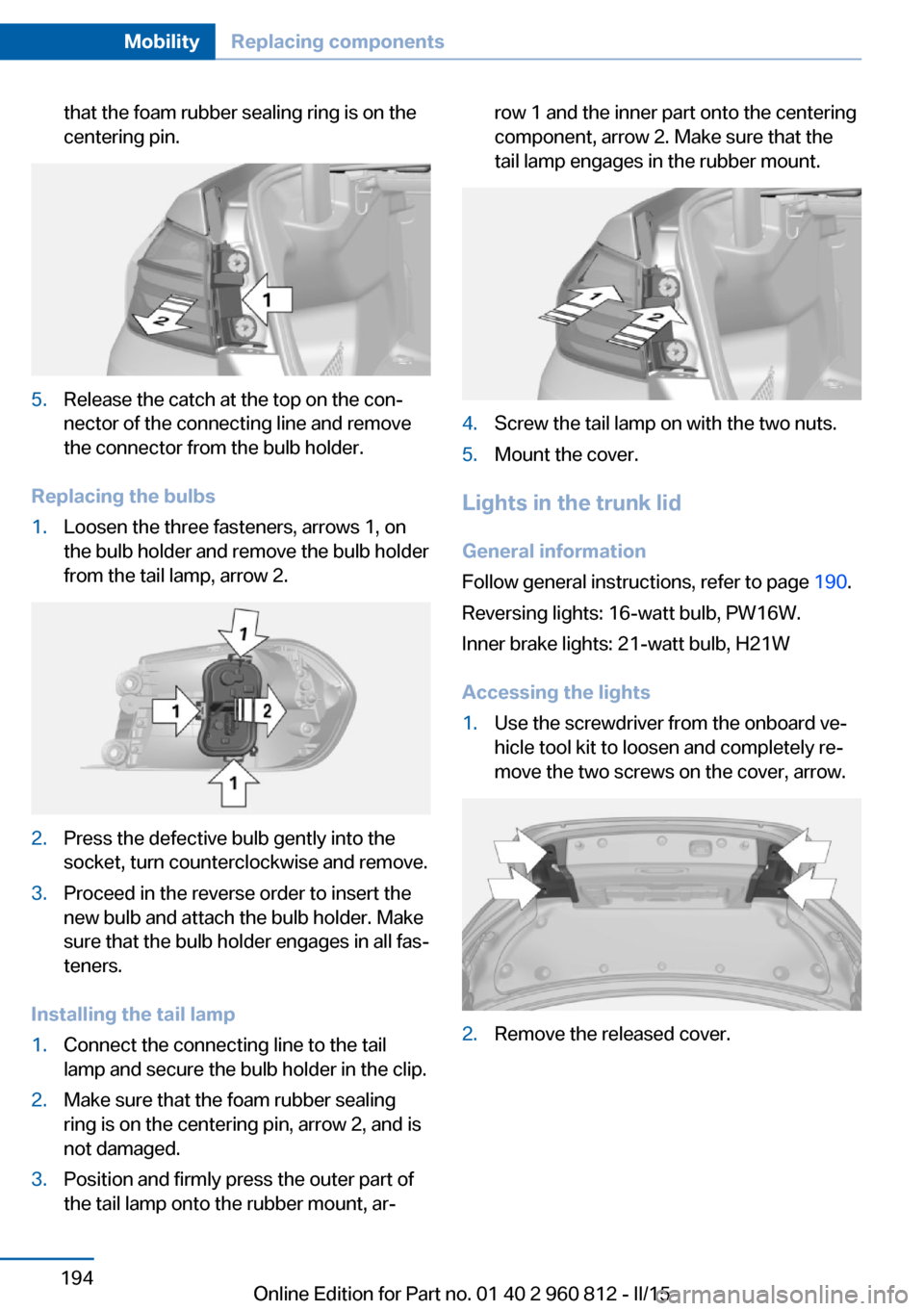
that the foam rubber sealing ring is on the
centering pin.5.Release the catch at the top on the con‐
nector of the connecting line and remove
the connector from the bulb holder.
Replacing the bulbs
1.Loosen the three fasteners, arrows 1, on
the bulb holder and remove the bulb holder
from the tail lamp, arrow 2.2.Press the defective bulb gently into the
socket, turn counterclockwise and remove.3.Proceed in the reverse order to insert the
new bulb and attach the bulb holder. Make
sure that the bulb holder engages in all fas‐
teners.
Installing the tail lamp
1.Connect the connecting line to the tail
lamp and secure the bulb holder in the clip.2.Make sure that the foam rubber sealing
ring is on the centering pin, arrow 2, and is
not damaged.3.Position and firmly press the outer part of
the tail lamp onto the rubber mount, ar‐row 1 and the inner part onto the centering
component, arrow 2. Make sure that the
tail lamp engages in the rubber mount.4.Screw the tail lamp on with the two nuts.5.Mount the cover.
Lights in the trunk lid
General information
Follow general instructions, refer to page 190.
Reversing lights: 16-watt bulb, PW16W.
Inner brake lights: 21-watt bulb, H21W
Accessing the lights
1.Use the screwdriver from the onboard ve‐
hicle tool kit to loosen and completely re‐
move the two screws on the cover, arrow.2.Remove the released cover.Seite 194MobilityReplacing components194
Online Edition for Part no. 01 40 2 960 812 - II/15
Page 199 of 226

Replacing the reversing lamp and inner
brake lamp1.Loosen the bottom holder, arrow 1.2.Loosen the top holder, arrow 2. To do so,
press in the middle latch and then press
out both outside latches.
Remove the lamp holder, arrow 3.3.Unscrew the defective bulb of the revers‐
ing or brake lamp from its socket counter‐
clockwise.4.Insert the new bulb.
Installing the bulb holder
1.Insert the two contacts, arrow 1, into the
connections, arrow 2.2.Press on the bulb holder, arrow 3. Make
sure that the two exterior holders latch into
place.3.Reattach the two covers to the trunk lid.
Rear lamp, license plate lamp and
central brake lamp
Follow general instructions, refer to page 190.
These lights are made using LED technology.
Contact your service center in the event of a
malfunction.
Changing wheels
Hints When sealants are used, an immediate wheel
change when there is a loss of tire inflation
pressure in the event of a flat tire is unneces‐
sary.
Which is why no spare tire is available.
The tools for changing wheels are available as
accessories from your service center.
Jacking points for the vehicle jack
The jacking points for the vehicle jack are lo‐
cated at the positions shown.
Vehicle battery Maintenance
The battery is maintenance-free.
Further information about the battery can be
obtained from your service center.
Battery replacement Use approved vehicle batteries only
Only use vehicle batteries that have been
approved for your vehicle by the manufacturer;
otherwise, the vehicle could be damaged and
Seite 195Replacing componentsMobility195
Online Edition for Part no. 01 40 2 960 812 - II/15