2016 BMW M4 CONVERTIBLE turn signal
[x] Cancel search: turn signalPage 116 of 226

Lane departure warningThe concept Starting at a specific speed, this system alerts
you when the vehicle on streets with lane
markings is about to leave the lane. This
speed, depending on the country version, is
between 35 mph/55 km/h and
45 mph/70 km/h.
When switching on the system below this
speed, a message is displayed in the instru‐
ment cluster.
The steering wheel begins vibrating gently in
the event of warnings. The time of the warning
may vary depending on the current driving sit‐
uation.
The system does not provide a warning if the
turn signal is set before leaving the lane.
Hints Personal responsibility
The system cannot serve as a substitute
for the driver's personal judgment of the
course of the road and the traffic situation.
In the event of a warning, do not jerk the steer‐
ing wheel, as you may lose control of the vehi‐
cle.◀
At a glance
Button in the vehicle
Lane departure warning
Camera
The camera is found near the interior rearview
mirror.
Keep the windshield in the area behind the in‐
terior rearview mirror clean and clear.
Switching on/off Press button.
▷On: the LED lights up.▷Off: the LED goes out.
Settings are stored for the profile currently in
use.
Display in the instrument cluster
▷Lines: system is activated.▷Arrows: at least one lane marking
was detected and warnings can be
issued.
Issued warning
If you leave the lane and if a lane marking has
been detected, the steering wheel begins vi‐
brating.
If the turn signal is set before changing the
lane, a warning is not issued.
End of warning
The warning ends:
▷Automatically after approx. 3 seconds.▷When returning to your own lane.▷When braking hard.Seite 112ControlsSafety112
Online Edition for Part no. 01 40 2 960 812 - II/15
Page 117 of 226

▷When using the turn signal.
System limits
The system may not be fully functional in the
following situations:
▷In heavy fog, rain or snowfall.▷In the event of missing, worn, poorly visi‐
ble, merging, diverging, or multiple lane
markings such as in construction areas.▷When lane markings are covered in snow,
ice, dirt or water.▷In tight curves or on narrow lanes.▷When the lane markings are covered by
objects.▷When driving very close to the vehicle in
front of you.▷When driving toward bright lights.▷When the windshield in front of the interior
rearview mirror is fogged over, dirty or cov‐
ered with stickers, etc.▷During calibration of the camera immedi‐
ately after vehicle shipment.
Active Blind Spot Detection
The concept
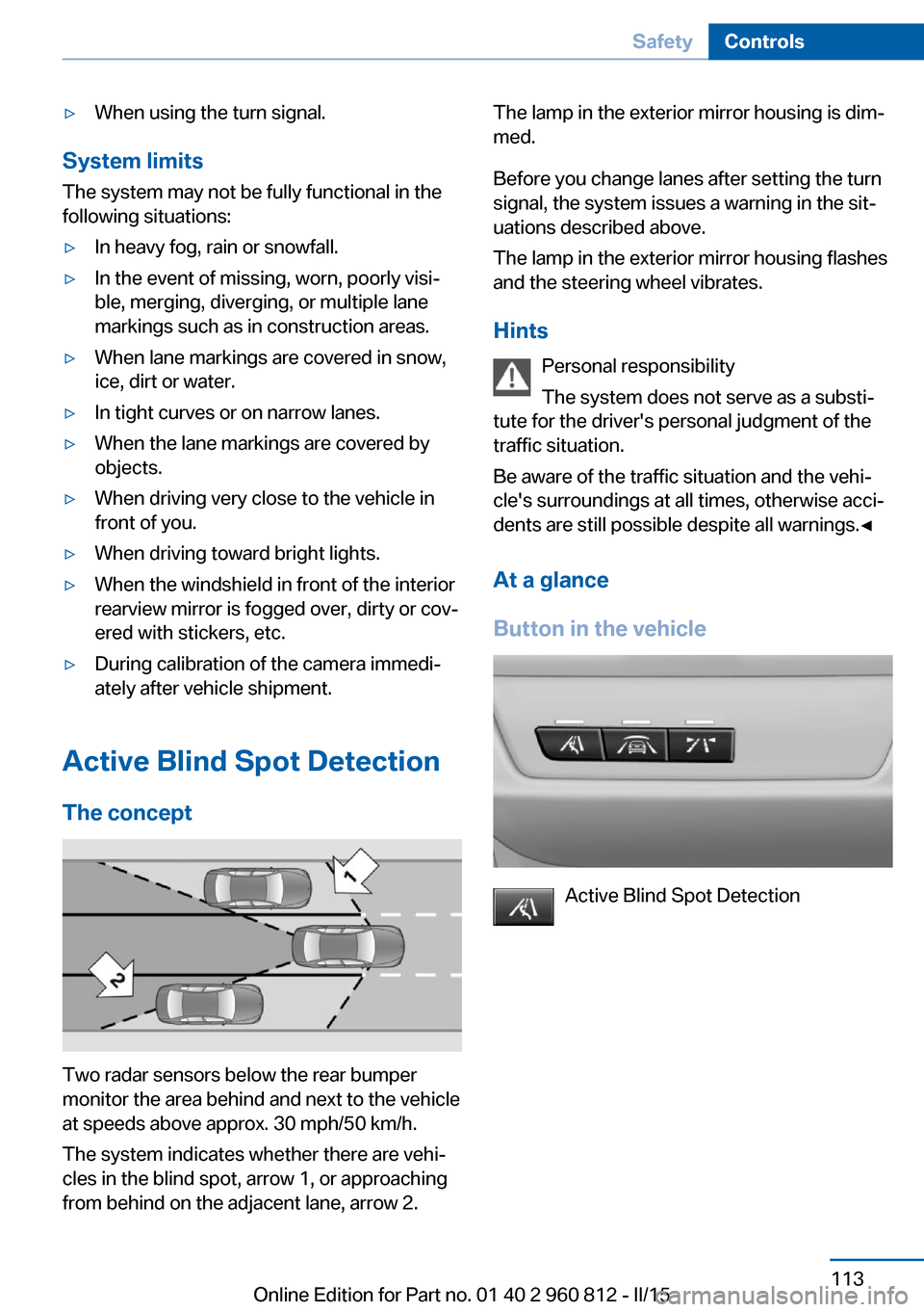
Two radar sensors below the rear bumper
monitor the area behind and next to the vehicle
at speeds above approx. 30 mph/50 km/h.
The system indicates whether there are vehi‐
cles in the blind spot, arrow 1, or approaching
from behind on the adjacent lane, arrow 2.
The lamp in the exterior mirror housing is dim‐
med.
Before you change lanes after setting the turn
signal, the system issues a warning in the sit‐
uations described above.
The lamp in the exterior mirror housing flashes
and the steering wheel vibrates.
Hints Personal responsibility
The system does not serve as a substi‐
tute for the driver's personal judgment of the
traffic situation.
Be aware of the traffic situation and the vehi‐
cle's surroundings at all times, otherwise acci‐
dents are still possible despite all warnings.◀
At a glance
Button in the vehicle
Active Blind Spot Detection
Seite 113SafetyControls113
Online Edition for Part no. 01 40 2 960 812 - II/15
Page 118 of 226

Radar sensors
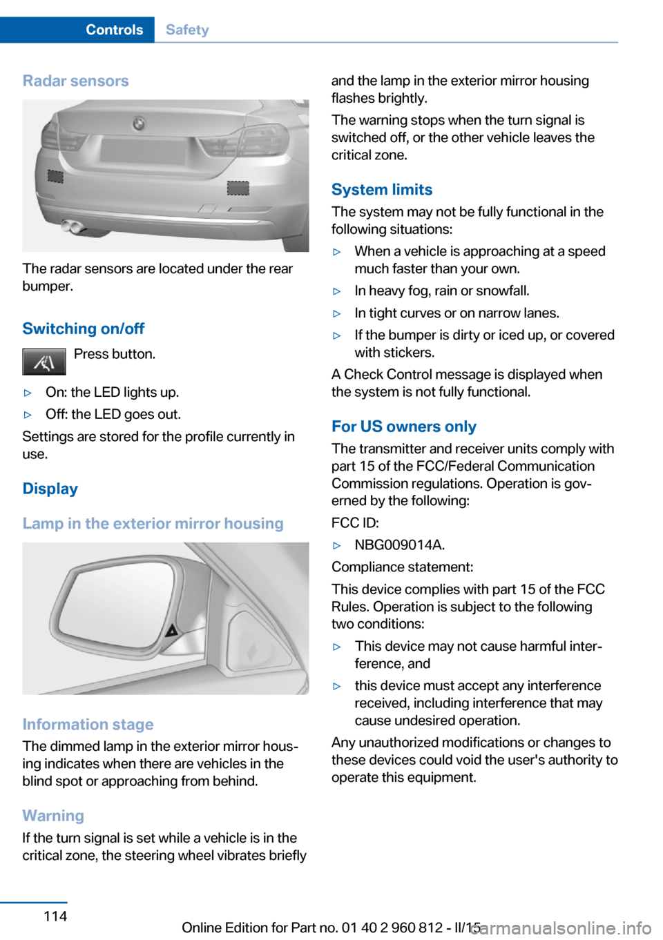
The radar sensors are located under the rear
bumper.
Switching on/off Press button.
▷On: the LED lights up.▷Off: the LED goes out.
Settings are stored for the profile currently in
use.
Display
Lamp in the exterior mirror housing
Information stage
The dimmed lamp in the exterior mirror hous‐
ing indicates when there are vehicles in the
blind spot or approaching from behind.
Warning If the turn signal is set while a vehicle is in the
critical zone, the steering wheel vibrates briefly
and the lamp in the exterior mirror housing
flashes brightly.
The warning stops when the turn signal is
switched off, or the other vehicle leaves the
critical zone.
System limits
The system may not be fully functional in the
following situations:▷When a vehicle is approaching at a speed
much faster than your own.▷In heavy fog, rain or snowfall.▷In tight curves or on narrow lanes.▷If the bumper is dirty or iced up, or covered
with stickers.
A Check Control message is displayed when
the system is not fully functional.
For US owners only The transmitter and receiver units comply with
part 15 of the FCC/Federal Communication
Commission regulations. Operation is gov‐
erned by the following:
FCC ID:
▷NBG009014A.
Compliance statement:
This device complies with part 15 of the FCC
Rules. Operation is subject to the following
two conditions:
▷This device may not cause harmful inter‐
ference, and▷this device must accept any interference
received, including interference that may
cause undesired operation.
Any unauthorized modifications or changes to
these devices could void the user's authority to
operate this equipment.
Seite 114ControlsSafety114
Online Edition for Part no. 01 40 2 960 812 - II/15
Page 137 of 226

▷Maximum distance to row of parked vehi‐
cles: 5 ft/1.5 m.
Suitable parking space
▷Gap between two objects with a minimum
length of approx. 5 ft/1.5 m.▷Min. length of gap between two objects:
your vehicle's length plus approx.
4 ft/1.2 m.▷Minimum depth: approx. 5 ft/1.5 m.
Regarding the parking procedure
▷Doors and trunk lid closed.▷Parking brake released.▷When parking in parking spaces on the
driver's side, the corresponding turn signal
must be set where applicable.
Overview
Button in the vehicle
Parking assistant
Ultrasound sensors
The ultrasound sensors for measuring parking
spaces are located on the side of the vehicle.
To ensure full functionality:
▷Keep the sensors clean and free of ice.▷When using high-pressure washers, do not
spray the sensors for long periods and
maintain a distance of at least 12 in/30 cm.▷Do not put stickers over sensors.
Switching on/off
Switching on with the button Press button.
The LED lights up.
The current status of the parking space search
is indicated on the Control Display.
Parking assistant is activated automatically.
Switching on with the reverse gear
Shift into reverse.
The current status of the parking space search
is indicated on the Control Display.
To activate:
"Parking Assistant"
Switch off
The system can be deactivated as follows:
▷Press button.▷Switch off the ignition.Seite 133Driving comfortControls133
Online Edition for Part no. 01 40 2 960 812 - II/15
Page 139 of 226

▷Possible on snow-covered or slippery road
surfaces.▷When there are obstacles that are hard to
overcome, such as curbs.▷When there are obstacles that suddenly
arise.▷If the Park Distance Control PDC displays
clearances that are too small.▷If a maximum number of parking attempts
or the time taken for parking is exceeded.▷If a turn signal has been actuated contrary
to the desired side for parking.▷When switching to another function on the
Control Display.
A Check Control message is displayed.
Flashing display on the selector lever
of the double clutch transmission
The actually engaged transmission position
can deviate from the selector lever position in
some situations after function interruption.
The display in the selector lever flashes.
Observe the display in the instrument cluster,
refer to page 73, in these cases.
Resume An interrupted parking procedure can be con‐
tinued if needed.
Follow the instructions on the Control Display
to do this.
System limits
No parking assistance
The parking assistant does not offer assis‐
tance in the following situations:
▷In tight curves.
Functional limitations
The system may not be fully functional in the
following situations:
▷On bumpy road surfaces such as gravel
roads.▷On slippery ground.▷On steep uphill or downhill grades.▷With accumulations of leaves/snow in the
parking space.
Limits of ultrasonic measurement
Ultrasonic measuring might not function under
the following circumstances:
▷For small children and animals.▷For persons with certain clothing, e.g.
coats.▷With external interference of the ultra‐
sound, e.g. from passing vehicles or loud
machines.▷When sensors are dirty, iced over, dam‐
aged or out of position.▷Under certain weather conditions such as
high relative humidity, rain, snowfall, ex‐
treme heat or strong wind.▷With tow bars and trailer couplings of other
vehicles.▷With thin or wedge-shaped objects.▷With moving objects.▷With elevated, protruding objects such as
ledges or cargo.▷With objects with corners and sharp edges.▷With objects with a fine surface structure
such as fences.▷For objects with porous surfaces.
Low objects already displayed, e.g., curbs, can
move into the blind area of the sensors before
or after a continuous tone sounds.
The parking assistant may identify parking
spaces that are not suitable for parking.
Malfunction
A Check Control message is displayed.
The parking assistant failed. Have the system
checked.
Seite 135Driving comfortControls135
Online Edition for Part no. 01 40 2 960 812 - II/15
Page 196 of 226

Headlights1Parking lights / daytime running lights2Low beams/high beams/headlight flasher3Turn signal
Low beams and high beams are designed with
xenon technology.
The parking lights and daylight running lights
are made using LED technology.
Contact your service center in the event of a
malfunction.
Turn signal
Follow general instructions, refer to page 190.
21-watt bulb, PY21W
1.In the wheel house, unscrew three screws
using the screwdriver from the onboard ve‐
hicle tool kit, arrow 1.2.Lift the wheel house panel and firmly hold
it, arrow 2.3.Turn the bulb socket counterclockwise and
remove.4.Press the bulb gently into the socket, turn
counterclockwise and remove.5.Install the new bulb and bulb holder in re‐
verse order of removal.6.Refasten the wheel house panel.
LED headlights
Light-emitting diodes (LEDs)
With LED headlights, all front lights and side
indicators are designed with LED technology.
Contact your service center in the event of a
malfunction.
Headlights
1Cornering light2Low beams/headlight flasher3High beams/headlight flasher4Parking lights / daytime running lights5Turn signal6Side marker lightsSeite 192MobilityReplacing components192
Online Edition for Part no. 01 40 2 960 812 - II/15
Page 197 of 226

Contact your service center in the event of a
malfunction.
Turn signal in exterior mirrorFollow general instructions, refer to page 190.
The turn signals in the exterior mirrors feature
LED technology. Contact your service center in the event of a malfunction.
Tail lights, bulb replacement
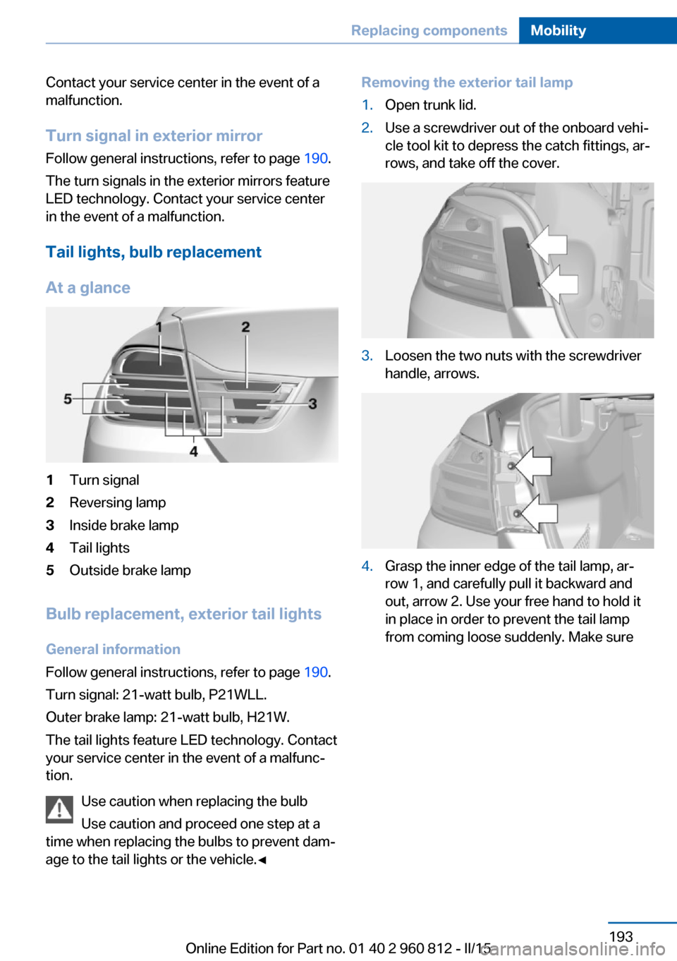
At a glance1Turn signal2Reversing lamp3Inside brake lamp4Tail lights5Outside brake lamp
Bulb replacement, exterior tail lights General information
Follow general instructions, refer to page 190.
Turn signal: 21-watt bulb, P21WLL.
Outer brake lamp: 21-watt bulb, H21W.
The tail lights feature LED technology. Contact
your service center in the event of a malfunc‐
tion.
Use caution when replacing the bulb
Use caution and proceed one step at a
time when replacing the bulbs to prevent dam‐
age to the tail lights or the vehicle.◀
Removing the exterior tail lamp1.Open trunk lid.2.Use a screwdriver out of the onboard vehi‐
cle tool kit to depress the catch fittings, ar‐
rows, and take off the cover.3.Loosen the two nuts with the screwdriver
handle, arrows.4.Grasp the inner edge of the tail lamp, ar‐
row 1, and carefully pull it backward and
out, arrow 2. Use your free hand to hold it
in place in order to prevent the tail lamp
from coming loose suddenly. Make sureSeite 193Replacing componentsMobility193
Online Edition for Part no. 01 40 2 960 812 - II/15
Page 205 of 226

Tow-starting and towingNote Tow-starting and towing
For tow-starting or towing, switch off the
Intelligent Safety systems; otherwise malfunc‐
tions of the individual braking systems might
lead to accidents.◀
Manual transmission Gearshift lever in neutral position.
Towing Follow the towing instructions
Follow all towing instructions; otherwise,
vehicle damage or accidents may occur.◀▷Make sure that the ignition is switched on;
otherwise, the low beams, tail lights, turn
signals, and wipers may be unavailable.▷Do not tow the vehicle with the rear axle
tilted, as the front wheels could turn.▷When the engine is stopped, there is no
power assist. Consequently, more force
needs to be applied when braking and
steering.▷Larger steering wheel movements are re‐
quired.▷The towing vehicle must not be lighter
than the vehicle being towed; otherwise,
it will not be possible to control the vehi‐
cle's response.Tow truck
With rear-wheel drive
Your vehicle should be transported with a tow
truck with a so-called lift bar or on a flat bed.
Do not lift the vehicle
Do not lift the vehicle by the tow fitting or
body and chassis parts; otherwise, damage
may result.◀
M double clutch transmission:
transporting your vehicle
Note Your vehicle is not permitted to be towed.
Therefore, contact a service center in the
event of a breakdown.
Do not have the vehicle towedHave your vehicle transported on a load‐
ing platform only; otherwise, damage may oc‐
cur.◀
Seite 201Breakdown assistanceMobility201
Online Edition for Part no. 01 40 2 960 812 - II/15