Page 186 of 232

4.Slide the sealing container upright into the
holder on the compressor housing, ensur‐
ing that it engages audibly.5.Screw the connection hose onto the tire
valve of the defective wheel.6.With the compressor switched off, insert
the plug into a power socket inside the ve‐
hicle.7.With the ignition turned on or the engine
running, reel on the compressor.
Switch off the compressor after 10 mi‐
nutes
Do not allow the compressor to run longer than
10 minutes; otherwise, the device will overheat
and may be damaged.◀
Let the compressor run for approx. 3 to 8 mi‐
nutes to fill the tire with sealant and achieve a
tire inflation pressure of approx. 2.5 bar.
While the tire is being filled with sealant, the
tire inflation pressure may sporadically reach
approx. 5 bar. Do not reel off the compressor at
this point.
If a tire inflation pressure of 2 bar is not
reached:
1.Switch off the compressor.2.Unscrew the filling hose from the wheel.3.Drive 33 ft/10 m forward and back to dis‐
tribute the sealant in the tire.4.Inflate the tire again using the compressor.
If a tire inflation pressure of 2 bar cannot be
reached, contact your service center.
Stowing the Mobility System
1.Remove the connection hose of the seal‐
ant container from the wheel.2.Remove the connection hose from the
sealant container.Seite 182MobilityWheels and tires182
Online Edition for Part no. 01 40 2 961 270 - II/15
Page 187 of 232

3.Wrap the empty sealant container and con‐
nection hose in suitable material to avoid
dirtying the cargo area.4.Stow the Mobility System back in the vehi‐
cle.
Distributing the sealant
Immediately drive approx. 5 miles/10 km to en‐
sure that the sealant is evenly distributed in the
tire.
Do not exceed a speed of 50 mph/80 km/h.
If possible, do not drive at speeds less than
12 mph/20 km/h.
To correct the tire inflation pressure
1.Stop at a suitable location.2.Screw the connection hose onto the tire
valve stem.3.Attach the connection hose directly to the
compressor.4.Insert the connector into a power socket
inside the vehicle.5.Correct the tire inflation pressure to
2.5 bar.▷Increase pressure: with the ignition
turned on or the engine running, reel
on the compressor.▷To reduce the pressure: press the but‐
ton on the compressor.
Continuing the trip
Do not exceed the maximum permissible
speed of 50 mph/80 km/h.
Reinitialize the Flat Tire Monitor.
Reinitialize the Tire Pressure Monitor.
Replace the defective tire and the sealant con‐
tainer of the Mobility System as soon as possi‐
ble.
Snow chains Fine-link snow chains
Only certain types of fine-link snow chains
have been tested by the manufacturer of the
vehicle, classified as road-safe and approved.
Information about the approved snow chains
are available from the service center.
Use
Use only in pairs on the rear wheels, equipped
with the tires of the following size:
▷205/55 R 16.Seite 183Wheels and tiresMobility183
Online Edition for Part no. 01 40 2 961 270 - II/15
Page 188 of 232
▷205/50 R 17.▷225/45 R 17.
Follow the snow chain manufacturer's instruc‐
tions.
Make sure that the snow chains are always
sufficiently tight. Retighten as needed accord‐
ing to the chain manufacturer's instructions.
Do not initialize the Flat Tire Monitor after
mounting snow chains, as doing so may result
in incorrect readings.
Do not initialize the Tire Pressure Monitor after
mounting snow chains, as doing so may result
in incorrect readings.
When driving with snow chains, briefly activate
Dynamic Traction Control if needed.
Maximum speed with snow chains Do not exceed a speed of 30 mph/50 km/hwhen using snow chains.
Seite 184MobilityWheels and tires184
Online Edition for Part no. 01 40 2 961 270 - II/15
Page 199 of 232

Accessing the turn signals and low beams
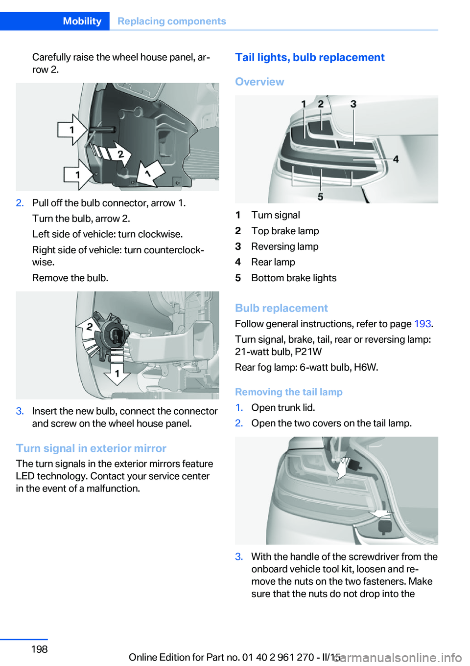
Follow general instructions, refer to page 193.1.In the wheel house, loosen the two brack‐
ets and remove the cover.
Turn signal
21-watt bulb, PY21W
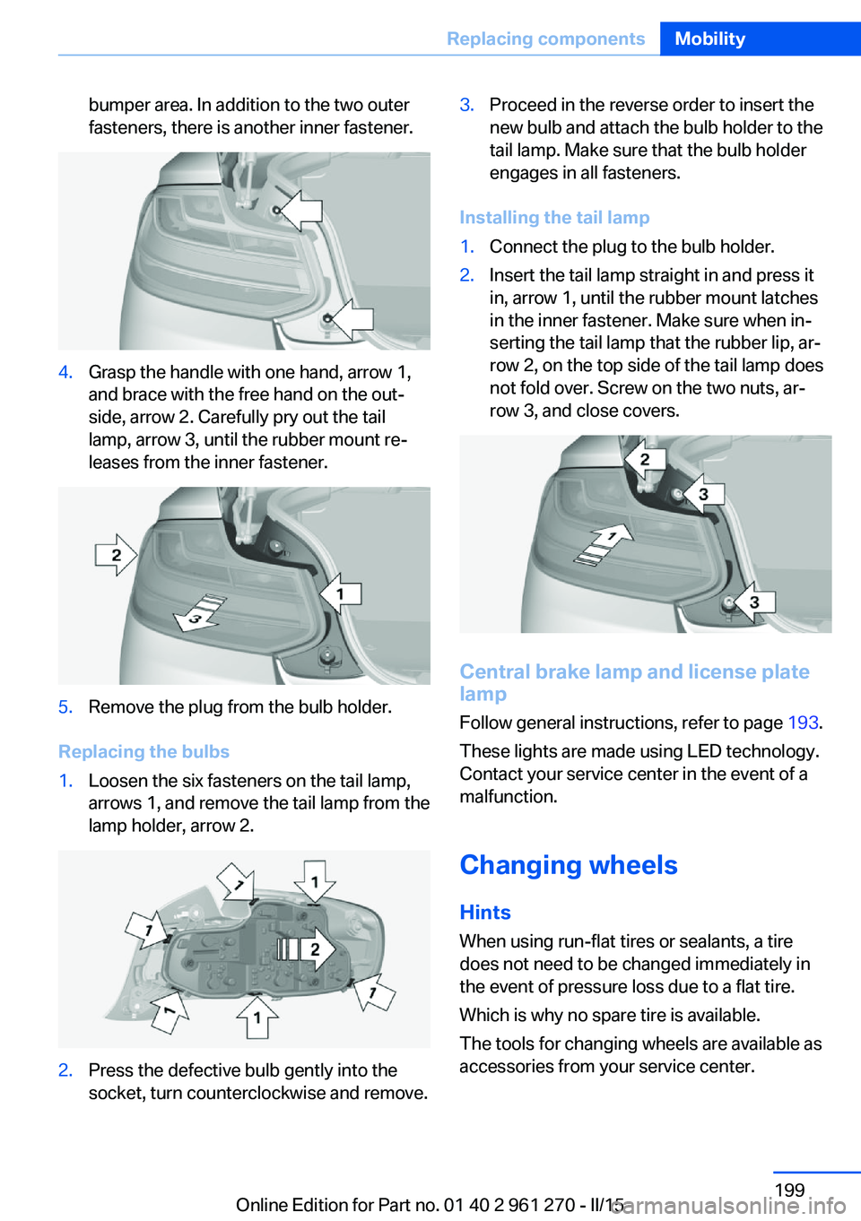
1.If necessary, pull the inside trim of the
wheel house slightly inward. Turn the bulb
socket counterclockwise and remove.2.Press the bulb gently into the socket, turn
counterclockwise and remove.3.Install the new bulb and bulb holder in re‐
verse order of removal.4.Attach the cover to the wheel house.Low beams
55-watt bulb, H7.1.Turn the cover counterclockwise and re‐
move.2.Tilt the bulb down and then up to loosen it
from the holder and remove.3.Pull the connector off the bulb.4.Attach the connector to the new bulb.5.First insert the bulb at the top with the
strap, arrow 1, and then press down firmly,
arrow 2. The bulb must audibly latch in
place.6.Close the headlight housing with the lid.
Make sure that the lid engages.7.Attach the cover to the wheel house.Seite 195Replacing componentsMobility195
Online Edition for Part no. 01 40 2 961 270 - II/15
Page 201 of 232

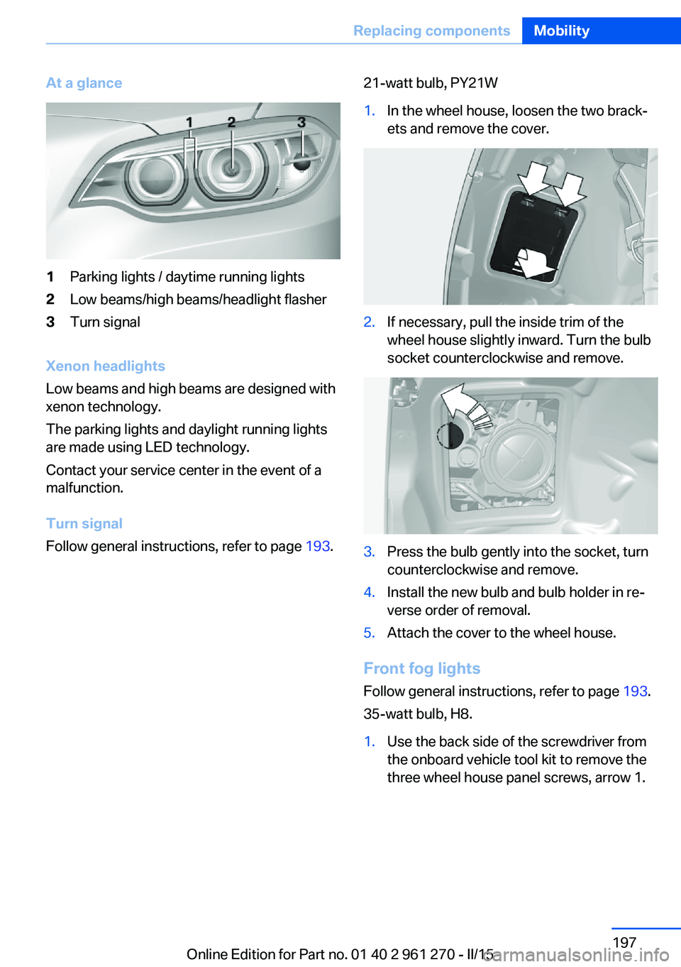
At a glance1Parking lights / daytime running lights2Low beams/high beams/headlight flasher3Turn signal
Xenon headlights
Low beams and high beams are designed with
xenon technology.
The parking lights and daylight running lights
are made using LED technology.
Contact your service center in the event of a
malfunction.
Turn signal
Follow general instructions, refer to page 193.
21-watt bulb, PY21W1.In the wheel house, loosen the two brack‐
ets and remove the cover.2.If necessary, pull the inside trim of the
wheel house slightly inward. Turn the bulb
socket counterclockwise and remove.3.Press the bulb gently into the socket, turn
counterclockwise and remove.4.Install the new bulb and bulb holder in re‐
verse order of removal.5.Attach the cover to the wheel house.
Front fog lights
Follow general instructions, refer to page 193.
35-watt bulb, H8.
1.Use the back side of the screwdriver from
the onboard vehicle tool kit to remove the
three wheel house panel screws, arrow 1.Seite 197Replacing componentsMobility197
Online Edition for Part no. 01 40 2 961 270 - II/15
Page 202 of 232

Carefully raise the wheel house panel, ar‐
row 2.2.Pull off the bulb connector, arrow 1.
Turn the bulb, arrow 2.
Left side of vehicle: turn clockwise.
Right side of vehicle: turn counterclock‐
wise.
Remove the bulb.3.Insert the new bulb, connect the connector
and screw on the wheel house panel.
Turn signal in exterior mirror
The turn signals in the exterior mirrors feature
LED technology. Contact your service center
in the event of a malfunction.
Tail lights, bulb replacement
Overview1Turn signal2Top brake lamp3Reversing lamp4Rear lamp5Bottom brake lights
Bulb replacement Follow general instructions, refer to page 193.
Turn signal, brake, tail, rear or reversing lamp:
21-watt bulb, P21W
Rear fog lamp: 6-watt bulb, H6W.
Removing the tail lamp
1.Open trunk lid.2.Open the two covers on the tail lamp.3.With the handle of the screwdriver from the
onboard vehicle tool kit, loosen and re‐
move the nuts on the two fasteners. Make
sure that the nuts do not drop into theSeite 198MobilityReplacing components198
Online Edition for Part no. 01 40 2 961 270 - II/15
Page 203 of 232

bumper area. In addition to the two outer
fasteners, there is another inner fastener.4.Grasp the handle with one hand, arrow 1,
and brace with the free hand on the out‐
side, arrow 2. Carefully pry out the tail
lamp, arrow 3, until the rubber mount re‐
leases from the inner fastener.5.Remove the plug from the bulb holder.
Replacing the bulbs
1.Loosen the six fasteners on the tail lamp,
arrows 1, and remove the tail lamp from the
lamp holder, arrow 2.2.Press the defective bulb gently into the
socket, turn counterclockwise and remove.3.Proceed in the reverse order to insert the
new bulb and attach the bulb holder to the
tail lamp. Make sure that the bulb holder
engages in all fasteners.
Installing the tail lamp
1.Connect the plug to the bulb holder.2.Insert the tail lamp straight in and press it
in, arrow 1, until the rubber mount latches
in the inner fastener. Make sure when in‐
serting the tail lamp that the rubber lip, ar‐
row 2, on the top side of the tail lamp does
not fold over. Screw on the two nuts, ar‐
row 3, and close covers.
Central brake lamp and license plate
lamp
Follow general instructions, refer to page 193.
These lights are made using LED technology.
Contact your service center in the event of a
malfunction.
Changing wheels
Hints
When using run-flat tires or sealants, a tire
does not need to be changed immediately in
the event of pressure loss due to a flat tire.
Which is why no spare tire is available.
The tools for changing wheels are available as
accessories from your service center.
Seite 199Replacing componentsMobility199
Online Edition for Part no. 01 40 2 961 270 - II/15
Page 209 of 232

Tow-starting and towingNote Tow-starting and towing
For tow-starting or towing, switch off the
Intelligent Safety systems; otherwise malfunc‐
tions of the individual braking systems might
lead to accidents.◀
Manual transmission Gearshift lever in neutral position.
Towing Follow the towing instructions
Follow all towing instructions; otherwise,
vehicle damage or accidents may occur.◀▷Make sure that the ignition is switched on;
otherwise, the low beams, tail lights, turn
signals, and wipers may be unavailable.▷Do not tow the vehicle with the rear axle
tilted, as the front wheels could turn.▷When the engine is stopped, there is no
power assist. Consequently, more force
needs to be applied when braking and
steering.▷Larger steering wheel movements are re‐
quired.▷The towing vehicle must not be lighter
than the vehicle being towed; otherwise,
it will not be possible to control the vehi‐
cle's response.Tow truck
With rear-wheel drive
Your vehicle should be transported with a tow
truck with a so-called lift bar or on a flat bed.
Do not lift the vehicle
Do not lift the vehicle by the tow fitting or
body and chassis parts; otherwise, damage
may result.◀
With xDrive
The vehicle should only be transported on a
loading platform.
Do not tow with only the front or rear axle
raised
Do not tow the BMW with just the front or rear
axle raised; otherwise, the wheels could lock
up and the transfer case could be damaged.◀
Do not lift the vehicle
Do not lift the vehicle by the tow fitting or
body and chassis parts; otherwise, damage
may result.◀
Seite 205Breakdown assistanceMobility205
Online Edition for Part no. 01 40 2 961 270 - II/15