2016 BMW M235I COUPE ESP
[x] Cancel search: ESPPage 78 of 232
▷In addition to the briefly pulled right shift
paddle, briefly pull the left shift paddle.
In the manual mode, after conservative driving
for a certain amount of time or if there has
been no acceleration or shifting of the shift
paddles within a certain amount of time, the
transmission switches back to automatic
mode.
Displays in the instrument cluster The selector lever position is dis‐
played, e.g.: P.
Electronic unlocking of the
transmission lock
General information
Electronically unlock the transmission lock to
maneuver vehicle from the danger area.
Unlocking is possible, if the started can spin
the engine.
Engaging selector lever position N
1.Depress the brake pedal.2.Press the Start/Stop button. The starter
must audibly start.3.Press and hold the selector lever into posi‐
tion N.
A corresponding Check Control message
is displayed.4.Press the selector lever again into posi‐
tion N within approx. 6 seconds.
Position N is displayed in the instrument
cluster.5.Release brake, as soon as the starter
stops.6.Maneuver the vehicle from the danger area
and secure it against moving on its own.Steptronic Sport transmission:
Launch Control
The concept Launch Control enables optimum accelerationon surfaces with good traction.
Hints Component wear
Do not use Launch Control too often;
otherwise, this may result in premature wear of
components due to the high stress placed on
the vehicle.◀
Do not use Launch Control during the break-in,
refer to page 152, period.
To increase vehicle stability, activate DSC
again as soon as possible.
An experienced driver may be able to achieve
better acceleration values in DSC OFF mode.
Requirements Launch Control is available when the engine is
warmed up, that is, after uninterrupted driving
of at least 6 miles/10 km.
To start with Launch Control do not steer the
steering wheel.
Start with launch controlWhile the engine is running:1. Press button or select Sport+ with
the Driving Dynamics Control.
TRACTION is displayed in the instrument
cluster and the indicator lamp for DSC OFF
lights up.2.Engage selector lever position S.3.With the left foot, forcefully press down on
the brake.4.Press and hold down the accelerator pedal
beyond the resistance point at the full
throttle position.Seite 74ControlsDriving74
Online Edition for Part no. 01 40 2 961 270 - II/15
Page 80 of 232
DisplaysVehicle features and optionsThis chapter describes all standard, country-
specific and optional features offered with the
series. It also describes features that are not
necessarily available in your car, e. g., due tothe selected options or country versions. This
also applies to safety-related functions and
systems. The respectively applicable country
provisions must be observed when using the
respective features and systems.
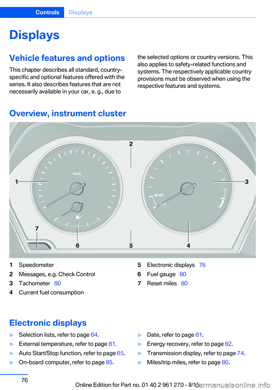
Overview, instrument cluster
1Speedometer2Messages, e.g. Check Control3Tachometer 804Current fuel consumption5Electronic displays 766Fuel gauge 807Reset miles 80
Electronic displays
▷Selection lists, refer to page 84.▷External temperature, refer to page 81.▷Auto Start/Stop function, refer to page 65.▷On-board computer, refer to page 85.▷Date, refer to page 81.▷Energy recovery, refer to page 82.▷Transmission display, refer to page 74.▷Miles/trip miles, refer to page 80.Seite 76ControlsDisplays76
Online Edition for Part no. 01 40 2 961 270 - II/15
Page 89 of 232
Display
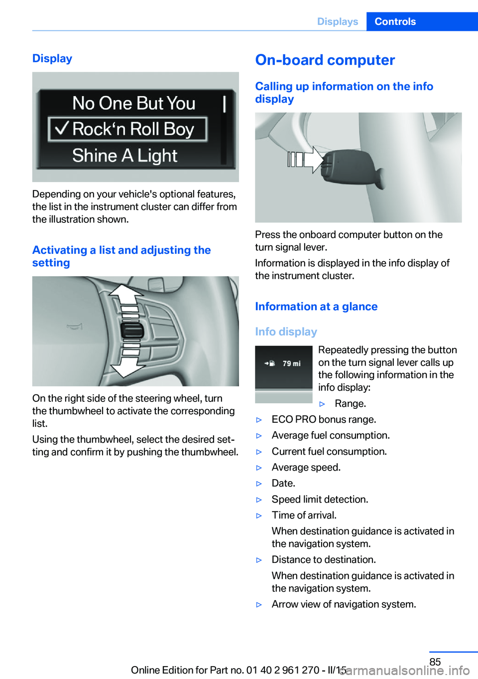
Depending on your vehicle's optional features,
the list in the instrument cluster can differ from
the illustration shown.
Activating a list and adjusting the
setting
On the right side of the steering wheel, turn
the thumbwheel to activate the corresponding
list.
Using the thumbwheel, select the desired set‐
ting and confirm it by pushing the thumbwheel.
On-board computer
Calling up information on the info
display
Press the onboard computer button on the
turn signal lever.
Information is displayed in the info display of
the instrument cluster.
Information at a glance
Info display Repeatedly pressing the button
on the turn signal lever calls up
the following information in the
info display:
▷Range.▷ECO PRO bonus range.▷Average fuel consumption.▷Current fuel consumption.▷Average speed.▷Date.▷Speed limit detection.▷Time of arrival.
When destination guidance is activated in
the navigation system.▷Distance to destination.
When destination guidance is activated in
the navigation system.▷Arrow view of navigation system.Seite 85DisplaysControls85
Online Edition for Part no. 01 40 2 961 270 - II/15
Page 94 of 232
LightsVehicle features and optionsThis chapter describes all standard, country-
specific and optional features offered with the
series. It also describes features that are not
necessarily available in your car, e. g., due to
the selected options or country versions. This
also applies to safety-related functions and
systems. The respectively applicable country
provisions must be observed when using the
respective features and systems.
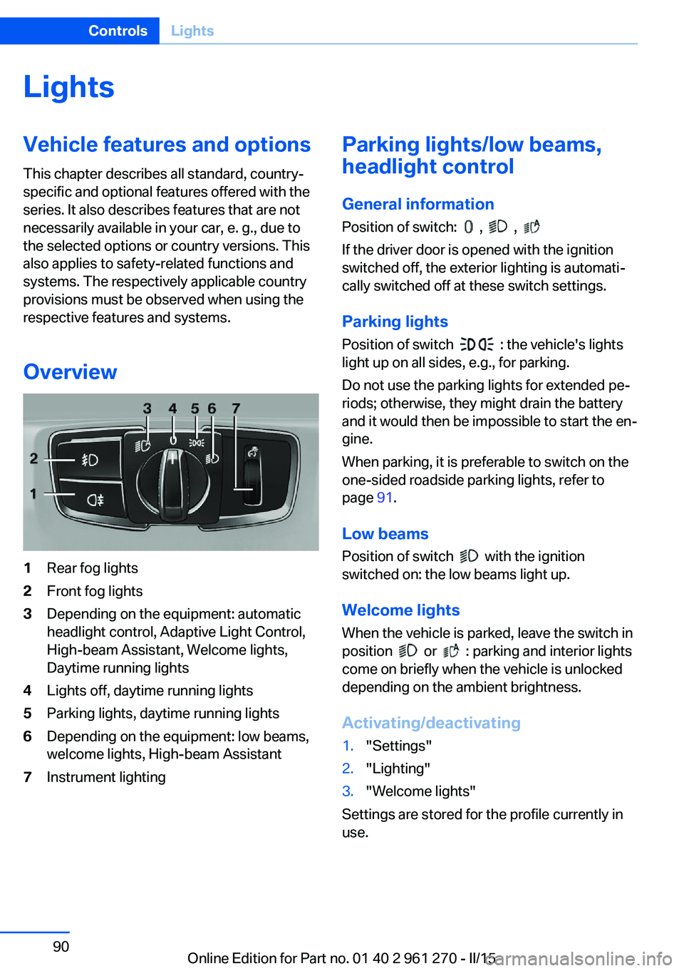
Overview1Rear fog lights2Front fog lights3Depending on the equipment: automatic
headlight control, Adaptive Light Control,
High-beam Assistant, Welcome lights,
Daytime running lights4Lights off, daytime running lights5Parking lights, daytime running lights6Depending on the equipment: low beams,
welcome lights, High-beam Assistant7Instrument lightingParking lights/low beams,
headlight control
General information
Position of switch:
, ,
If the driver door is opened with the ignition
switched off, the exterior lighting is automati‐
cally switched off at these switch settings.
Parking lights
Position of switch
: the vehicle's lights
light up on all sides, e.g., for parking.
Do not use the parking lights for extended pe‐
riods; otherwise, they might drain the battery
and it would then be impossible to start the en‐
gine.
When parking, it is preferable to switch on the
one-sided roadside parking lights, refer to
page 91.
Low beams Position of switch
with the ignition
switched on: the low beams light up.
Welcome lights
When the vehicle is parked, leave the switch in
position
or : parking and interior lights
come on briefly when the vehicle is unlocked
depending on the ambient brightness.
Activating/deactivating
1."Settings"2."Lighting"3."Welcome lights"
Settings are stored for the profile currently in
use.
Seite 90ControlsLights90
Online Edition for Part no. 01 40 2 961 270 - II/15
Page 95 of 232
Headlight courtesy delay featureThe low beams stay lit for a short while if the
headlight flasher is switched on after the radio-
ready state is switched off.
Setting the duration1."Settings"2."Lighting"3."Pathway lighting:"4.Set length of time.
Settings are stored for the profile currently in
use.
Automatic headlight control
Position of switch
: the low beams are acti‐
vated and off automatically, e.g., in tunnels, in
twilight or if there is precipitation. The indicator
lamp in the instrument cluster lights up.
When emerging from a tunnel during the day,
the low beams are not switched off immedi‐
ately but instead only after approx. 2 minutes.
A blue sky with the sun low on the horizon can
cause the lights to be switched on.
The low beams always stay on when the fog
lights are activated.
Personal responsibility
The automatic headlight control cannot
serve as a substitute for your personal judg‐
ment in determining when to turn the lights on
in response to ambient lighting conditions.
E. g. the sensors are unable to detect fog or
hazy weather. To avoid safety risks under
these conditions, you should always switch on
the lights manually.◀
Daytime running lights With the ignition switched on, the daytime run‐
ning lights light up in position
, or
. After the ignition is switched off, the park‐
ing lights light up in position
.
Activating/deactivating
In some countries, daytime running lights are
mandatory, so it may not be possible to deacti‐
vate the daytime running lights.1."Settings"2."Lighting"3."Daytime running lamps"
Settings are stored for the profile currently in
use.
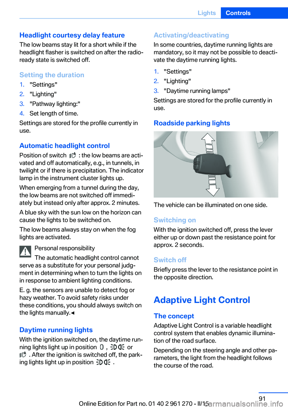
Roadside parking lights
The vehicle can be illuminated on one side.
Switching on With the ignition switched off, press the lever
either up or down past the resistance point for
approx. 2 seconds.
Switch off Briefly press the lever to the resistance point in
the opposite direction.
Adaptive Light Control The concept
Adaptive Light Control is a variable headlight
control system that enables dynamic illumina‐
tion of the road surface.
Depending on the steering angle and other pa‐ rameters, the light from the headlight follows
the course of the road.
Seite 91LightsControls91
Online Edition for Part no. 01 40 2 961 270 - II/15
Page 96 of 232
In tight curves, e.g., on mountainous roads or
when turning, one of the two front fog lights is
switched on as a turning lamp. As a result the
inside of the curve is better lighted.
ActivatingPosition of switch
with the ignition
switched on.
To avoid blinding oncoming traffic, the Adap‐
tive Light Control does not swivel to the driv‐
er's side when the vehicle is at a standstill.
The turning lights are automatically switched
on depending on the steering angle or the use
of turn signals.
When driving in reverse, the turning lights may
be automatically switched on regardless of the
steering angle.
Malfunction A Check Control message is displayed.
Adaptive Light Control is malfunctioning or has
failed. Have the system checked as soon as
possible.
High-beam Assistant
The concept When the low beams are activated, this system
automatically switches the high beams on and
off or suppresses the light in the areas that
blind oncoming traffic. The procedure is con‐
trolled by a camera on the front of the interior
rearview mirror. The assistant ensures that the
high beams are activated whenever the traffic
situation allows. The driver can intervene at
any time and switch the high beams non and
off as usual.
Note Personal responsibility
The High-beam Assistant cannot serve
as a substitute for the driver's personal judg‐
ment of when to use the high beams. There‐
fore, manually reel off the high beams in situa‐
tions where required to avoid a safety risk.◀
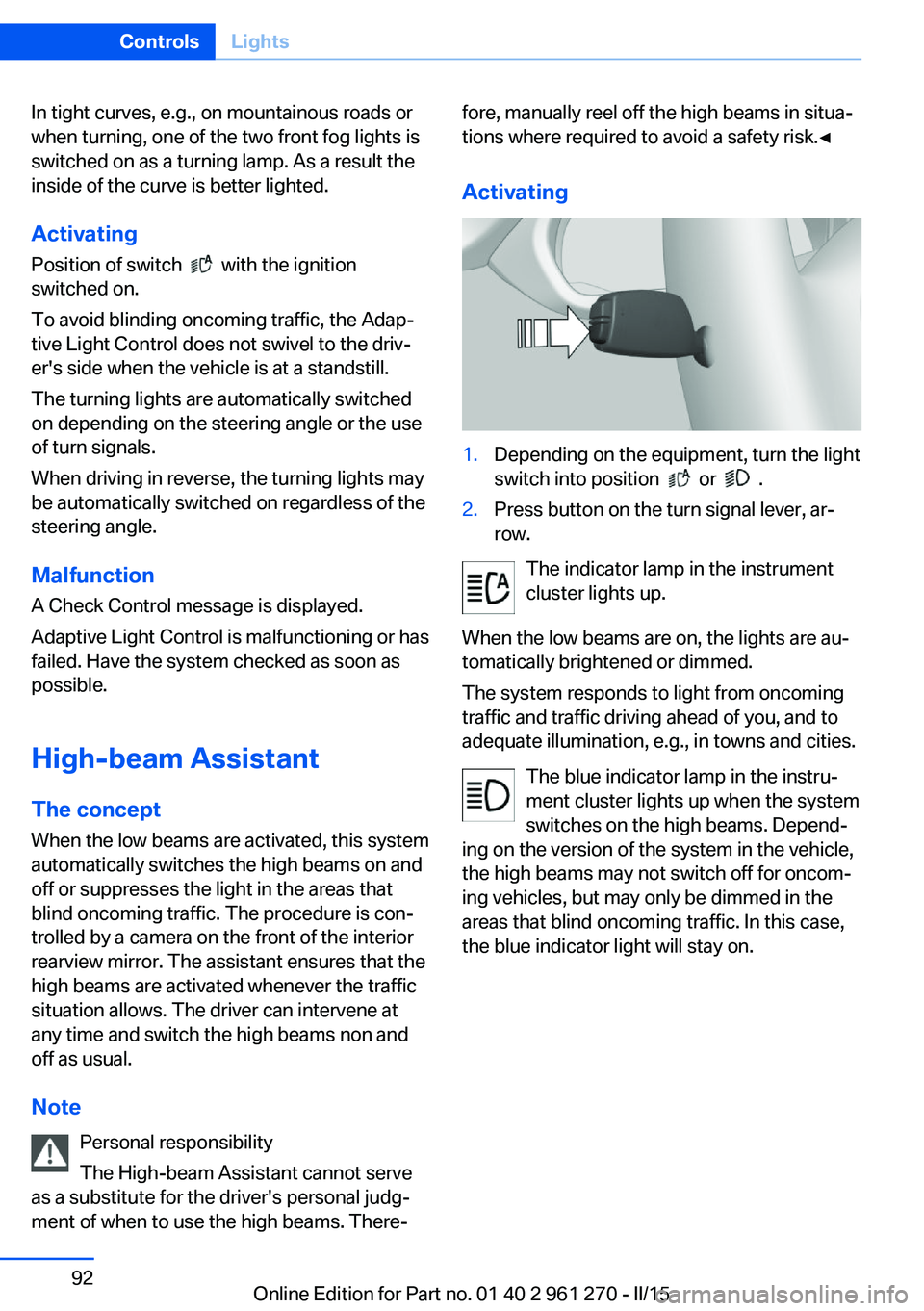
Activating1.Depending on the equipment, turn the light
switch into position
or .
2.Press button on the turn signal lever, ar‐
row.
The indicator lamp in the instrument
cluster lights up.
When the low beams are on, the lights are au‐
tomatically brightened or dimmed.
The system responds to light from oncoming
traffic and traffic driving ahead of you, and to
adequate illumination, e.g., in towns and cities.
The blue indicator lamp in the instru‐
ment cluster lights up when the system
switches on the high beams. Depend‐
ing on the version of the system in the vehicle, the high beams may not switch off for oncom‐
ing vehicles, but may only be dimmed in the
areas that blind oncoming traffic. In this case,
the blue indicator light will stay on.
Seite 92ControlsLights92
Online Edition for Part no. 01 40 2 961 270 - II/15
Page 99 of 232
SafetyVehicle features and options
This chapter describes all standard, country-
specific and optional features offered with the
series. It also describes features that are not
necessarily available in your car, e. g., due tothe selected options or country versions. This
also applies to safety-related functions and
systems. The respectively applicable country
provisions must be observed when using the
respective features and systems.
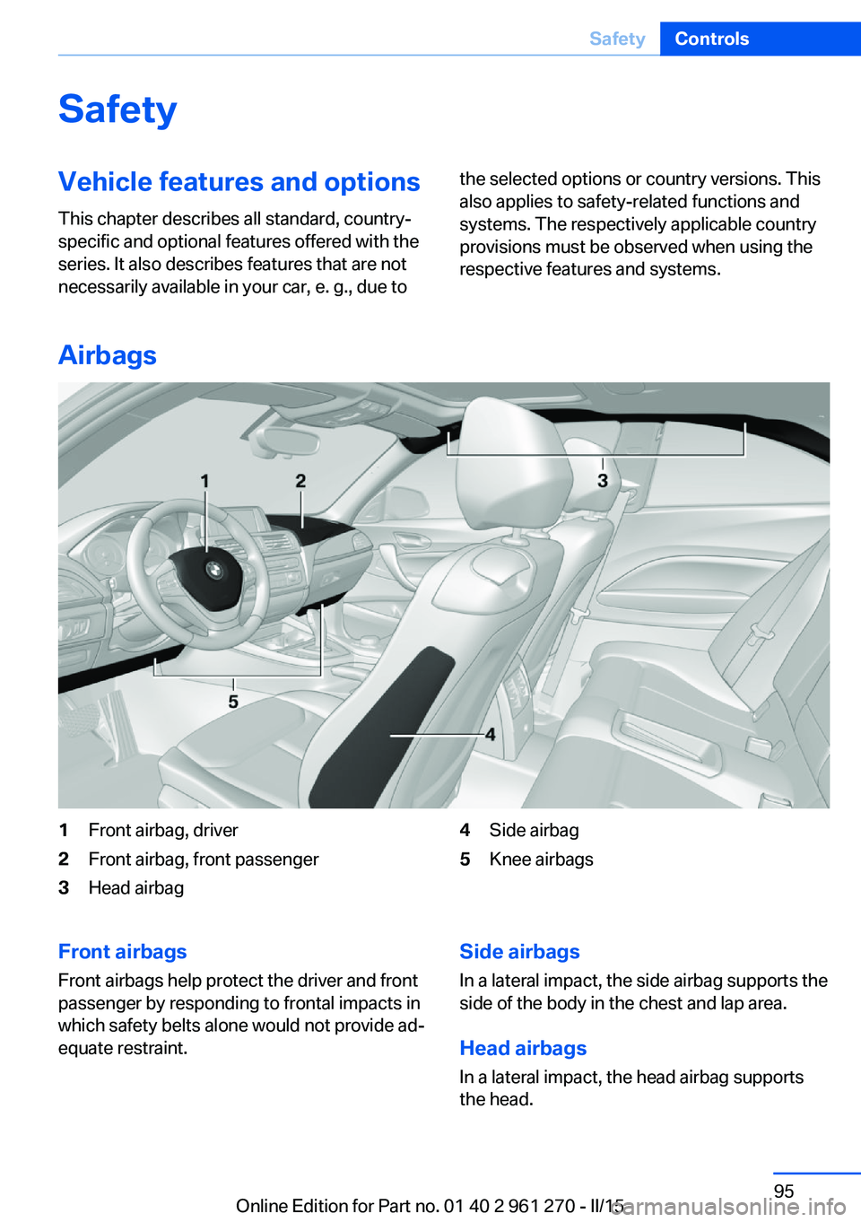
Airbags
1Front airbag, driver2Front airbag, front passenger3Head airbag4Side airbag5Knee airbagsFront airbags
Front airbags help protect the driver and front
passenger by responding to frontal impacts in
which safety belts alone would not provide ad‐
equate restraint.Side airbags
In a lateral impact, the side airbag supports the
side of the body in the chest and lap area.
Head airbags
In a lateral impact, the head airbag supports
the head.Seite 95SafetyControls95
Online Edition for Part no. 01 40 2 961 270 - II/15
Page 102 of 232
size is detected on the seat. The airbags
on the front passenger side are activated.
Detected child seats
The system generally detects children seated
in a child seat, particularly in child seats re‐
quired by NHTSA when the vehicle was manu‐ factured. After installing a child seat, make
sure that the indicator lamp for the front-seat
passenger airbags lights up. This indicates
that the child seat has been detected and the
front-seat passenger airbags are not activated.
Strength of the driver's and front-seat
passenger airbag
The explosive power that activates driver's/
front passenger's airbags very much depends
on the positions of the driver's/front passeng‐ er's seat.
With a respective message appearing on Con‐
trol Display calibrate the front seats to keep the accuracy of this function over the long-
term.
Calibrating the front seats
A corresponding message appears on the
Control Display.
1.Press the reel and move the respective
seat all the way forward.2.Press the reel forward again. The seat still
moves forward slightly.3.Readjust the seat to the desired position.
The calibration procedure is completed when
the message on the Control Display disap‐
pears.
If the message continues to be displayed, re‐
peat the calibration.
If the message does not disappear after a re‐
peat calibration, have the system checked as
soon as possible.
Unobstructed area of movement
Ensure that the area of movement of the
seats is unobstructed to avoid personal injury
or damage to objects.◀
Tire Pressure Monitor TPM The concept
The system monitors tire inflation pressure in
the four mounted tires. The system warns you
if there is a significant loss of pressure in one
or more tires. For this purpose, sensors in the
tire valves measure the tire inflation pressure
and tire temperature.
Hints Tire damage due to external factors
Sudden tire damage caused by external
circumstances cannot be recognized in ad‐
vance.◀
With use of the system observe further infor‐
mation found under Tire inflation pressure, re‐
fer to page 172.
Functional requirements
The system must have been reset with the
correct tire inflation pressure; otherwise, relia‐
ble signaling of tire inflation pressure loss is
not assured.
Reset the system after each adjustment of the
tire inflation pressure and after every tire or
wheel change.
Always use wheels with TPM electronics to
ensure that the system will operate properly.
Status display
The current status of the Tire Pressure Moni‐
tor TPM can be displayed on the Control Dis‐
play, e.g., whether or not the TPM is active.1."Vehicle info"2."Vehicle status"Seite 98ControlsSafety98
Online Edition for Part no. 01 40 2 961 270 - II/15