Page 35 of 220

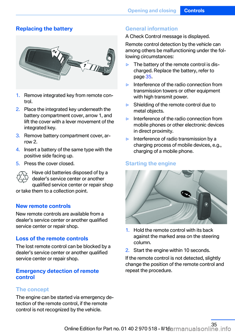
Replacing the battery1.Remove integrated key from remote con‐
trol.2.Place the integrated key underneath the
battery compartment cover, arrow 1, and
lift the cover with a lever movement of the
integrated key.3.Remove battery compartment cover, ar‐
row 2.4.Insert a battery of the same type with the
positive side facing up.5.Press the cover closed.
Have old batteries disposed of by a
dealer’s service center or another
qualified service center or repair shop
or take them to a collection point.
New remote controlsNew remote controls are available from a
dealer’s service center or another qualified
service center or repair shop.
Loss of the remote controls
The lost remote control can be blocked by a
dealer’s service center or another qualified
service center or repair shop.
Emergency detection of remote
control
The concept The engine can be started via emergency de‐
tection of the remote control, if the remote
control is not recognized by the vehicle.
General information
A Check Control message is displayed.
Remote control detection by the vehicle can
among others be malfunctioning under the fol‐
lowing circumstances:▷The battery of the remote control is dis‐
charged. Replace the battery, refer to
page 35.▷Interference of the radio connection from
transmission towers or other equipment
with high transmit power.▷Shielding of the remote control due to
metal objects.▷Interference of the radio connection from
mobile phones or other electronic devices
in direct proximity.▷Interference of radio transmission by a
charging process of mobile devices, e.g.,
charging of a mobile phone.
Starting the engine
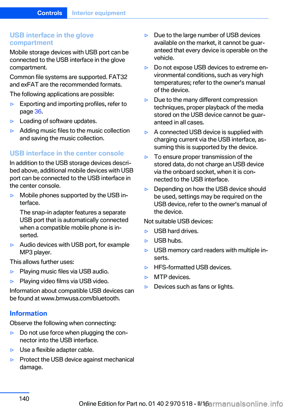
1.Hold the remote control with its back
against the marked area on the steering
column.2.Start the engine within 10 seconds.
If the remote control is not detected, slightly
change the position of the remote control and
repeat the procedure.
Seite 35Opening and closingControls35
Online Edition for Part no. 01 40 2 970 518 - II/16
Page 140 of 220

USB interface in the glove
compartment
Mobile storage devices with USB port can be
connected to the USB interface in the glove
compartment.
Common file systems are supported. FAT32
and exFAT are the recommended formats.
The following applications are possible:▷Exporting and importing profiles, refer to
page 36.▷Loading of software updates.▷Adding music files to the music collection
and saving the music collection.
USB interface in the center console
In addition to the USB storage devices descri‐
bed above, additional mobile devices with USB
port can be connected to the USB interface in
the center console.
▷Mobile phones supported by the USB in‐
terface.
The snap-in adapter features a separate
USB port that is automatically connected
when a compatible mobile phone is in‐
serted.▷Audio devices with USB port, for example
MP3 player.
This allows further uses:
▷Playing music files via USB audio.▷Playing video films via USB video.
Information about compatible USB devices can
be found at www.bmwusa.com/bluetooth.
Information Observe the following when connecting:
▷Do not use force when plugging the con‐
nector into the USB interface.▷Use a flexible adapter cable.▷Protect the USB device against mechanical
damage.▷Due to the large number of USB devices
available on the market, it cannot be guar‐
anteed that every device is operable on the
vehicle.▷Do not expose USB devices to extreme en‐
vironmental conditions, such as very high
temperatures; refer to the owner's manual
of the device.▷Due to the many different compression
techniques, proper playback of the media
stored on the USB device cannot be guar‐
anteed in all cases.▷A connected USB device is supplied with
charging current via the USB interface, as‐
suming this is supported by the device.▷To ensure proper transmission of the
stored data, do not charge an USB device
via the onboard socket, when it is con‐
nected to the USB interface.▷Depending on how the USB device should
be used, settings may be required on the
USB device, refer to the owner's manual of
the device.
Not suitable USB devices:
▷USB hard drives.▷USB hubs.▷USB memory card readers with multiple in‐
serts.▷HFS-formatted USB devices.▷MTP devices.▷Devices such as fans or lights.Seite 140ControlsInterior equipment140
Online Edition for Part no. 01 40 2 970 518 - II/16
Page 191 of 220

Check Control messages of these comfort fea‐
tures are no longer displayed.
Charging the battery
General information
Make sure that the battery is always suffi‐
ciently charged to guarantee that the battery
remains usable for its full service life.
The battery may need to be charged in the fol‐
lowing cases:▷When making frequent short-distance
drives.▷If the vehicle is not used for more than a
month.
Information
ATTENTION
Battery chargers for the vehicle battery
can work with high voltages and currents,
which means that the 12 volt on-board net‐
work can be overloaded or damaged. There is
a risk of damage to property. Only connect
battery chargers for the vehicle battery to the
starting aid terminals in the engine compart‐
ment.◀
Starting aid terminals In the vehicle, only charge the battery via the
starting aid terminals, refer to page 195, in the
engine compartment with the engine off.
Power failure After a power loss, some equipment needs to
be newly initialized or individual settings up‐
dated, for example:
▷Seat and mirror memory: store the posi‐
tions again.▷Time: update.▷Date: update.▷Glass sunroof and sliding visor: initialize
the system, refer to page 48.Disposing of old batteries
Have old batteries disposed of by a
dealer’s service center or another
qualified service center or repair shop
or take them to a collection point.
Maintain the battery in an upright position for
transport and storage. Secure the battery so
that it does not tip over during transport.
Fuses Information WARNING
Incorrect and repaired fuses can overload
electrical lines and components. There is risk
of fire. Never attempt to repair a blown fuse.
Do not replace a nonworking fuse with a sub‐
stitute of another color or amperage rating.◀
Plastic tweezers and information on the fuse
types and locations are stored in the fuse box
in the cargo area.
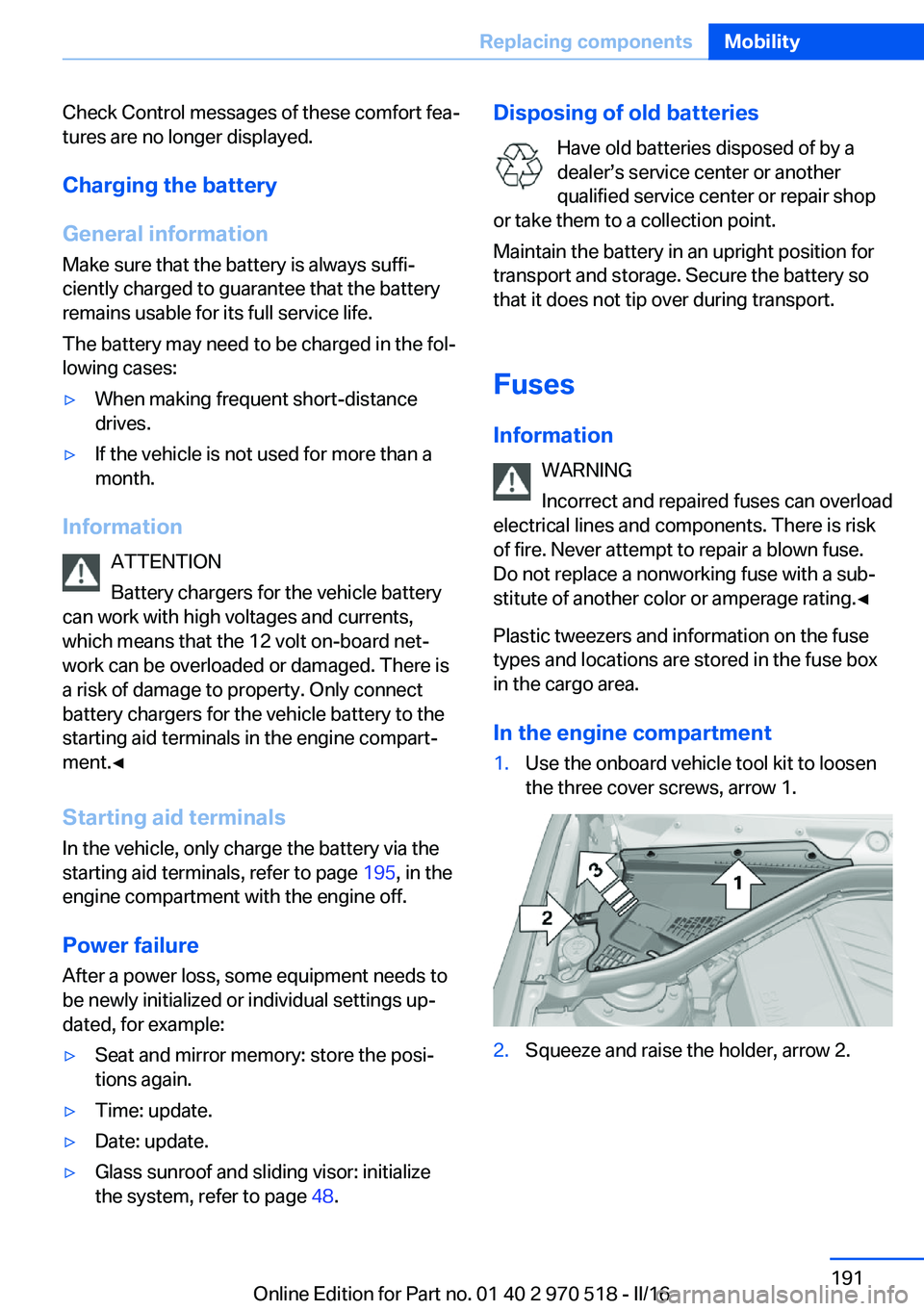
In the engine compartment1.Use the onboard vehicle tool kit to loosen
the three cover screws, arrow 1.2.Squeeze and raise the holder, arrow 2.Seite 191Replacing componentsMobility191
Online Edition for Part no. 01 40 2 970 518 - II/16