2016 BMW M2 engine
[x] Cancel search: enginePage 121 of 220

▷Each time the rocker switch is pressed to
the point of resistance, the desired speed
increases or decreases by approx.
1 mph/1 km/h.▷Each time the rocker switch is pressed
past the point of resistance, the desired
speed increases or decreases by a maxi‐
mum of 5 mph/10 km/h.
The maximum speed that can be set de‐
pends on the vehicle.▷Pressing the rocker switch to the resist‐
ance point and holding it accelerates or de‐
celerates the vehicle without requiring
pressure on the accelerator pedal.
After the rocker switch is released, the ve‐
hicle maintains its final speed. Pressing the
switch beyond the resistance point causes
the vehicle to accelerate more rapidly.
Continuing cruise control
General information
An interrupted cruise control can be continued
by calling up the stored speed.
In the following cases, the stored speed value
is deleted and cannot be called up again:
▷When the system is switched off.▷When the ignition is switched off.
Information
Make sure that the difference between current
speed and stored speed is not too large before
calling up the stored speed. Otherwise, unin‐
tentional braking or accelerating may occur.
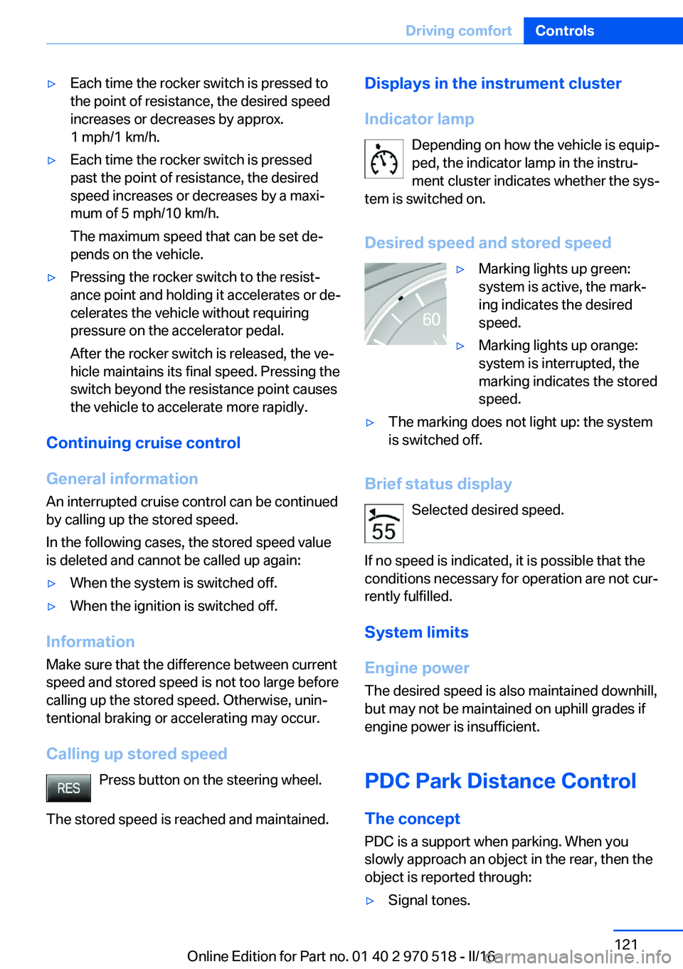
Calling up stored speed Press button on the steering wheel.
The stored speed is reached and maintained.
Displays in the instrument cluster
Indicator lamp Depending on how the vehicle is equip‐
ped, the indicator lamp in the instru‐
ment cluster indicates whether the sys‐
tem is switched on.
Desired speed and stored speed▷Marking lights up green:
system is active, the mark‐
ing indicates the desired
speed.▷Marking lights up orange:
system is interrupted, the
marking indicates the stored
speed.▷The marking does not light up: the system
is switched off.
Brief status display
Selected desired speed.
If no speed is indicated, it is possible that the
conditions necessary for operation are not cur‐
rently fulfilled.
System limits
Engine power The desired speed is also maintained downhill,
but may not be maintained on uphill grades if
engine power is insufficient.
PDC Park Distance Control The concept
PDC is a support when parking. When you
slowly approach an object in the rear, then the
object is reported through:
▷Signal tones.Seite 121Driving comfortControls121
Online Edition for Part no. 01 40 2 970 518 - II/16
Page 122 of 220

▷Visual display.
General information
Measurements are made through ultrasound
sensors in the rear bumper.
The maneuvering range, depending on the ob‐
stacle and environmental conditions, is approx.
6 ft/2 m.
An acoustic warning is first given with the fol‐
lowing circumstances:
▷By the two rear corner sensors at approx.
24 in/60 cm.▷By the rear middle sensors at approx.
5 ft/1.50 m.▷When a collision is imminent.
Information
WARNING
The system does not release from the
personal responsibility to correctly assess the
traffic situation. Based on the limits of the sys‐
tem, it cannot independently react to all traffic
situations. There is risk of an accident. Adjust
the driving style to the traffic conditions. Watch
traffic closely and actively intervene in the re‐
spective situations.◀
WARNING
Due to high speeds when PDC is acti‐
vated, the warning can be delayed due to
physical circumstances. There is a risk of injury
or risk of property damage. Avoid approaching
an object too fast. Avoid driving off fast while
PDC is not yet active.◀
Overview
Ultrasound sensors Ultrasound sensors of the PDC,
for example in the bumpers.
Functional requirements
To ensure full functionality:▷Do not cover sensors, for example, with
stickers, bicycle racks.▷Keep the sensors clean and free of ice.
To clean: when using high-pressure washers,
do not spray the sensors for long periods and
maintain a distance of at least 12 in‐
ches/30 cm.
Switching on/off
Switching on automatically
With the engine running, engage lever in posi‐
tion P R.
The rearview camera also switches on.
Automatic deactivation during forward
travel
The system switches off when a certain driving
distance or speed is exceeded.
Switch the system back on if needed.
Display
Signal tones When approaching an object, an intermittent
sound indicates the position of the object. E.g.
if an object is detected to the left rear of the
vehicle, a signal tone sounds from the left rear
speaker.
The shorter the distance to the object, the
shorter the intervals.
If the distance to a detected object is less than
approx. 10 inches/25 cm, a continuous tone is
sounded.
Volume The ratio of the PDC signal tone volume to the
entertainment volume can be adjusted.
1."Multimedia", "Radio" or "Settings"2."Tone"Seite 122ControlsDriving comfort122
Online Edition for Part no. 01 40 2 970 518 - II/16
Page 124 of 220

As soon as the malfunction due to other ultra‐
sound sources is no longer present, the sys‐
tem is again fully functional.
Malfunction
A Check Control message is displayed.
The range of the sensors is shown as a shaded
area on the Control Display.
PDC has failed. Have the system checked.
Rearview camera The concept
The rearview camera provides assistance in
parking and maneuvering backwards. The area
behind the vehicle is shown on the Control
Display.
Information WARNING
The system does not relieve from the
personal responsibility to correctly assess the
traffic situation. There is risk of an accident.
Adjust the driving style to the traffic condi‐
tions. Watch traffic and vehicle surroundings
closely and actively intervene in the respective
situations.◀Overview
Camera
The camera lens is located in the handle of the
tailgate. The image quality may be impaired by
dirt.
Clean the camera lens, refer to page 202.
Switching on/off
Switching on automatically With the engine running, engage lever in posi‐
tion P R.
The rearview camera image is displayed if the
system was switched on via the iDrive.
Automatic deactivation during forward
travel
The system switches off when a certain driving
distance or speed is exceeded.
Switch the system back on if needed.
Switching the view via iDrive With PDC activated:
"Rear view camera"
The rearview camera image is displayed.
Display on the Control Display
Functional requirement
▷The rearview camera is switched on.▷The tailgate is fully closed.Seite 124ControlsDriving comfort124
Online Edition for Part no. 01 40 2 970 518 - II/16
Page 128 of 220

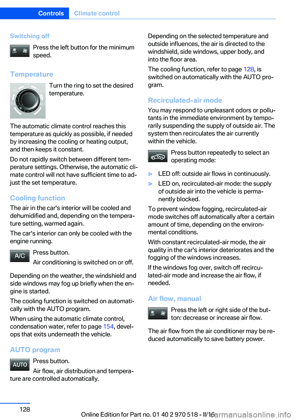
Switching offPress the left button for the minimum
speed.
Temperature Turn the ring to set the desired
temperature.
The automatic climate control reaches this
temperature as quickly as possible, if needed
by increasing the cooling or heating output,
and then keeps it constant.
Do not rapidly switch between different tem‐
perature settings. Otherwise, the automatic cli‐
mate control will not have sufficient time to ad‐
just the set temperature.
Cooling function The air in the car's interior will be cooled and
dehumidified and, depending on the tempera‐
ture setting, warmed again.
The car's interior can only be cooled with the
engine running.
Press button.
Air conditioning is switched on or off.
Depending on the weather, the windshield and
side windows may fog up briefly when the en‐
gine is started.
The cooling function is switched on automati‐
cally with the AUTO program.
When using the automatic climate control,
condensation water, refer to page 154, devel‐
ops that exits underneath the vehicle.
AUTO program Press button.
Air flow, air distribution and tempera‐
ture are controlled automatically.Depending on the selected temperature and
outside influences, the air is directed to the
windshield, side windows, upper body, and
into the floor area.
The cooling function, refer to page 128, is
switched on automatically with the AUTO pro‐
gram.
Recirculated-air mode You may respond to unpleasant odors or pollu‐
tants in the immediate environment by tempo‐
rarily suspending the supply of outside air. The
system then recirculates the air currently
within the vehicle.
Press button repeatedly to select an
operating mode:▷LED off: outside air flows in continuously.▷LED on, recirculated-air mode: the supply
of outside air into the vehicle is perma‐
nently blocked.
To prevent window fogging, recirculated-air
mode switches off automatically after a certain
amount of time, depending on the environ‐
mental conditions.
With constant recirculated-air mode, the air
quality in the car's interior deteriorates and the
fogging of the windows increases.
If the windows fog over, switch off recircu‐
lated-air mode and increase the air flow, if
needed.
Air flow, manual Press the left or right side of the but‐
ton: decrease or increase air flow.
The air flow from the air conditioner may be re‐
duced automatically to save battery power.
Seite 128ControlsClimate control128
Online Edition for Part no. 01 40 2 970 518 - II/16
Page 130 of 220

7Seat heating, right 528Cooling function9Automatic recirculated-air control/recircu‐
lated-air mode10Air distribution, right11Air flow, AUTO intensity12Air distribution, left13Rear window defroster14Interior temperature sensor — always keep
clear15Defrosts windows and removes condensa‐
tionClimate control functions in detail
Switching the system on/off
Switching on
Press any button except▷Rear window defroster.▷Seat heating.
Switching off
Press the left button for the minimum
speed.
Temperature Turn the ring to set the desired
temperature.
The automatic climate control reaches this
temperature as quickly as possible, if needed
by increasing the cooling or heating output,
and then keeps it constant.
Do not rapidly switch between different tem‐
perature settings. Otherwise, the automatic cli‐
mate control will not have sufficient time to ad‐
just the set temperature.
Cooling function The air in the car's interior will be cooled and
dehumidified and, depending on the tempera‐
ture setting, warmed again.
The car's interior can only be cooled with the
engine running.
Press button.
Air conditioning is switched on or off.
Depending on the weather, the windshield and
side windows may fog up briefly when the en‐
gine is started.
The cooling function is switched on automati‐
cally with the AUTO program.
When using the automatic climate control,
condensation water, refer to page 154, devel‐
ops that exits underneath the vehicle.
Maximum cooling Press button.
The system is set to the lowest tem‐
perature, optimum air flow and recirculated-air
mode.
Air flows out of the vents to the upper body re‐
gion. The vents need to be open for this.
The function is available above an external
temperature of approx. 32 ℉/0 ℃ And with the engine running.
Adjust air flow with the program active.
AUTO program Press button.
Air flow, air distribution and tempera‐
ture are controlled automatically.
Depending on the selected temperature,
AUTO intensity program and outside influen‐
ces, the air is directed to the windshield, side
windows, upper body, and into the floor area.Seite 130ControlsClimate control130
Online Edition for Part no. 01 40 2 970 518 - II/16
Page 136 of 220

4.Likewise, press and hold the button of the
desired function on the hand-held trans‐
mitter.5.Release both buttons as soon as the inte‐
rior mirror LED flashes more rapidly. The
LED flashing faster indicates that the but‐
ton on the interior mirror has been pro‐
grammed. The system can then be con‐
trolled by the button on the interior mirror.
If the LED does not flash faster after at
least 60 seconds, change the distance and
repeat the step. Several more attempts at
different distances may be necessary. Wait
at least 15 seconds between attempts.
Canada: if programming with the hand-
held transmitter was interrupted, hold
down the interior mirror button and repeat‐
edly press and release the hand-held
transmitter button for 2 seconds.
Controls
WARNING
Body parts can be jammed when operat‐
ing remote-controlled systems, e.g., the ga‐
rage door, using the integrated universal re‐
mote control. There is a risk of injury or risk of
property damage. Make sure that the area of
movement of the respective system is clear
during programming and operation. Also follow
the safety instructions of the hand-held trans‐
mitter.◀
The system, such as the garage door, can be
operated using the button on the interior mirror
while the engine is running or when the ignition is started. To do this, hold down the button
within receiving range of the system until the
function is activated. The interior mirror LED
stays lit while the wireless signal is being
transmitted.
Deleting stored functions Press and hold the left and right button on the
interior mirror simultaneously for approxi‐
mately 20 seconds until the LED flashes rap‐
idly. All stored functions will be deleted. The
functions cannot be deleted individually.
Digital compass
Overview1Control button2Mirror display
Mirror display
The point of the compass is displayed in the
mirror when driving straight.
Operating concept
Various functions can be called up by pressing
the control button with a pointed object, such
as the tip of a ballpoint pen or similar object.
The following setting options are displayed in
succession, depending on how long the con‐
trol button is pressed:
▷Pressed briefly: turns display on/off.▷3 to 6 seconds: compass zone setting.▷6 to 9 seconds: compass calibration.▷9 to 12 seconds: left/right-hand steering
setting.▷12 to 15 seconds: language setting.
Setting the compass zones
Sets the particular compass zones on the vehi‐
cle so that the compass operates correctly; re‐
fer to World map with compass zones.
Seite 136ControlsInterior equipment136
Online Edition for Part no. 01 40 2 970 518 - II/16
Page 138 of 220

Settings are stored automatically after approxi‐
mately 10 seconds.
Sun visor
Glare shield Fold the sun visor down or up.
Vanity mirror A vanity mirror is located in the sun visor be‐
hind a cover. When the cover is opened, the
mirror lighting switches on.
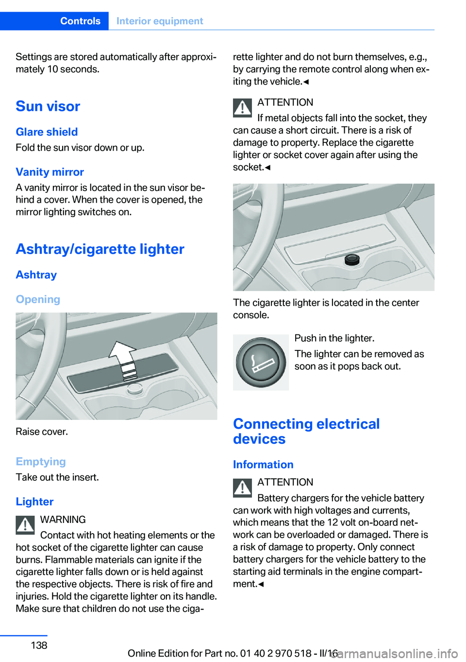
Ashtray/cigarette lighterAshtray
Opening
Raise cover.
EmptyingTake out the insert.
Lighter WARNING
Contact with hot heating elements or the
hot socket of the cigarette lighter can cause
burns. Flammable materials can ignite if the cigarette lighter falls down or is held against
the respective objects. There is risk of fire and
injuries. Hold the cigarette lighter on its handle.
Make sure that children do not use the ciga‐
rette lighter and do not burn themselves, e.g.,
by carrying the remote control along when ex‐
iting the vehicle.◀
ATTENTION
If metal objects fall into the socket, they
can cause a short circuit. There is a risk of
damage to property. Replace the cigarette
lighter or socket cover again after using the
socket.◀
The cigarette lighter is located in the center
console.
Push in the lighter.
The lighter can be removed as
soon as it pops back out.
Connecting electrical devices
Information ATTENTION
Battery chargers for the vehicle battery
can work with high voltages and currents,
which means that the 12 volt on-board net‐
work can be overloaded or damaged. There is
a risk of damage to property. Only connect
battery chargers for the vehicle battery to the
starting aid terminals in the engine compart‐
ment.◀
Seite 138ControlsInterior equipment138
Online Edition for Part no. 01 40 2 970 518 - II/16
Page 139 of 220

ATTENTION
If metal objects fall into the socket, they
can cause a short circuit. There is a risk of
damage to property. Replace the cigarette
lighter or socket cover again after using the
socket.◀
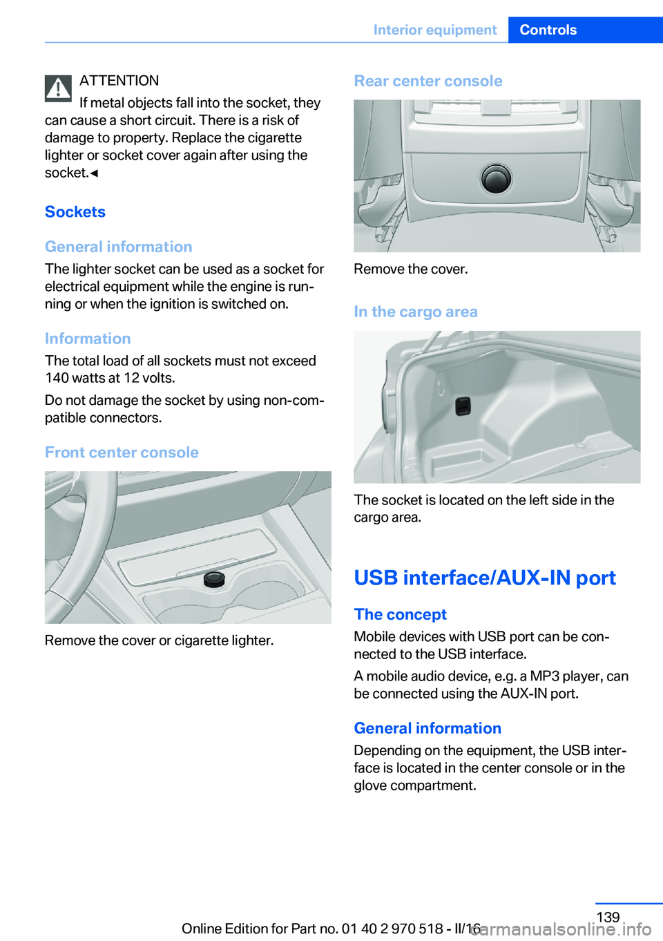
Sockets
General information
The lighter socket can be used as a socket for
electrical equipment while the engine is run‐
ning or when the ignition is switched on.
Information
The total load of all sockets must not exceed
140 watts at 12 volts.
Do not damage the socket by using non-com‐
patible connectors.
Front center console
Remove the cover or cigarette lighter.
Rear center console
Remove the cover.
In the cargo area
The socket is located on the left side in the
cargo area.
USB interface/AUX-IN port
The concept Mobile devices with USB port can be con‐
nected to the USB interface.
A mobile audio device, e.g. a MP3 player, can
be connected using the AUX-IN port.
General information Depending on the equipment, the USB inter‐
face is located in the center console or in the
glove compartment.
Seite 139Interior equipmentControls139
Online Edition for Part no. 01 40 2 970 518 - II/16